Design of Aviation High Impedance Permanent Magnet Synchronous Generator - Hindawi.com
←
→
Page content transcription
If your browser does not render page correctly, please read the page content below
Hindawi
Mathematical Problems in Engineering
Volume 2021, Article ID 6667877, 10 pages
https://doi.org/10.1155/2021/6667877

Research Article
Design of Aviation High Impedance Permanent Magnet
Synchronous Generator

 Shitao Wu ,1 Qingguang Chen ,1 Qing Li,2 Xiangsheng Liu ,3 Hailin Zhang,4 and Li Lin5
 1
 College of Mechanical and Electronic Engineering, Shandong University of Science and Technology, Qingdao,
 Shandong Province 266590, China
 2
 Information Management Office of Shanghai Ocean University, Shanghai 201306, China
 3
 College of Electronmechanical Engineering, Sanda University, Shanghai 201209, China
 4
 College of Management, Sanda University, Shanghai 201209, China
 5
 Planning and Technology Office of Sanda University, Shanghai 201209, China

 Correspondence should be addressed to Shitao Wu; wst@sdust.edu.cn

 Received 19 October 2020; Revised 17 February 2021; Accepted 7 April 2021; Published 26 April 2021

 Academic Editor: Marjan Uddin

 Copyright © 2021 Shitao Wu et al. This is an open access article distributed under the Creative Commons Attribution License,
 which permits unrestricted use, distribution, and reproduction in any medium, provided the original work is properly cited.
 Permanent magnet generator is one of the key components of a three-stage electrically excited brushless synchronous motor, with
 a main function to provide excitation power for the main exciter and driving power for the controller. In order to improve the
 reliability and safety of the operation of the three-stage electrically excited brushless synchronous motor, the permanent magnet
 generator is required to provide sufficient power under all operating conditions and to have low short-circuit current when its own
 short-circuit fault occurs, so that the generator will not be burnt out due to overheating. Thus, power characteristic and high
 impedance characteristic are the key goals of designing a permanent magnet generator. In this paper, the fractional slot
 concentrated winding was adopted to calculate and analyze the electromagnetic properties of permanent magnet generators with
 different rotor structures, and the optimal design was obtained. A prototype was manufactured to conduct related experiments on
 the electromagnetic properties. The results demonstrated that the experimental data are basically consistent with the simulation
 data, and the permanent magnet generator can meet the design requirements for power and high impedance characteristics, with a
 high power density.

1. Introduction (HVDC) power supply, constant speed constant frequency
 (CSCF) AC power supply, variable speed constant frequency
All-electric or more-electric system is an approach to achieve (VSCF) AC power supply, variable frequency variable speed
more fuel-efficient aircraft in the future which is easy to (VSVF) AC power supply, and hybrid power source. Owing
maintain [1, 2]. Characterized by large-capacity power to the mature technology, high reliability, and good
supply system and extensive use of electric actuator to re- maintainability, the three-stage electrically excited brushless
place hydraulic and pneumatic actuators with high failure synchronous motor can not only be used in CSCF, VSCF,
rates, all-electric or more-electric systems require the in- and VSVF power supply system but also can constitute
crease of capacity and reliability and the reduction in the LVDC and HVDC power supply system together with the
volume and weight of the power system. The power capacity output rectifier circuit, making it the preferred motor for the
of Airbus A380 and Boeing 787 is 840kVA and 1450kVA, large-capacity power supply system of all-electric or more-
respectively. With the development of the aviation power electric aircraft [3, 4].
system, the main power supply used in modern aircraft The typical structure of a three-stage electrically excited
includes the following types: 28 V low-voltage direct current brushless synchronous motor is shown in Figure 1. It
(LVDC) power supply, 270 V high-voltage direct current consists of three coaxially connected motors: a revolving
2 Mathematical Problems in Engineering

 Pre-exciter Main exciter Rotating Main generator
 (PE) (ME) rectifier (MG)

 ω
 ·
 ib Ief
 ·
 ic ·
 ia
 Rotor
 ω
 Stator
 · ·
 i sb i sB
 Ief
 · ·
 i sc · i sC ·
 i sa i sA

 Figure 1: Structure of the three-stage electrically excited brushless synchronous motor.

pole electrically excited synchronous motor (also known as of the short-circuit winding will rise rapidly, hence dam-
the main generator, MG), a revolving armature-type main aging the winding insulation and burning out the generator.
exciter (ME), and a revolving pole permanent magnet In addition, without electric energy output of the permanent
generator (also known as pre-exciter, PE). In the power magnet generator, the power system can only rely on 28 V
generation mode, the aeroengine drives the rotation of reserve power supply to provide excitation power and
system rotor, and the stator winding of the permanent driving power, which brings huge safety risks to the oper-
magnet generator cuts the synchronous rotating magnetic ation of the aircraft and threatens the lives of people on
field produced by the permanent magnet to generate three- board. Therefore, studying and analyzing the reliability and
phase alternating current, which provides DC exciting safety of the operation of permanent magnet generator are of
current for the excitation winding of ME and generates great theoretical and practical significance. Specifically, the
stator static magnetic field through the uncontrollable power and high impedance characteristics are key indicators
rectifier circuit and current regulating device. The armature for the design of the permanent magnet generator.
winding of ME cuts this magnetic field under the rotation
driven by the rotor and produces three-phase AC electric 2. Operating Principle
energy, which is supplied to the excitation winding of MG
through an uncontrollable revolving rectifier to establish its Permanent magnet generator used as PE has many
synchronous rotating magnetic field that is cut by the stator advantages:
winding of MG to generate electric energy for airborne
equipment. This is how a three-stage electrically excited (1) Without the excitation winding and the collector
brushless synchronous motor works in the power generation ring and brush that are prone to failure, losses can be
mode. reduced, and efficiency and operating reliability can
 Permanent magnet generator is one of the key com- be improved.
ponents of a three-stage electrically excited brushless syn- (2) The use of rare Earth permanent magnet can increase
chronous motor, and its electromagnetic properties are the air gap flux density, thereby significantly re-
crucial to the reliability and safety of power system opera- ducing the volume of the generator and increasing
tion. In fact, the permanent magnet generator has two main the power density. The aviation power system has
functions: first, as shown in Figure 1, the three-phase output extremely strict requirement for the weight of the
electric energy of the permanent magnet generator provides three-stage electrically excited brushless synchro-
excitation power for ME through the uncontrollable rectifier nous motor. The high power density of permanent
circuit and the current regulating device, so that MG can magnet synchronous generator makes it suitable to
achieve self-excited voltage build-up; second, the output be used as PE. At the same time, the permanent
electric energy of the permanent magnet generator provides magnet generator does not need an external mag-
the generator controller with the driving power needed for netic field, which is also the key to the realization of
its own operation, and the 28 V DC power supply inside the self-excited voltage build-up by the three-stage
controller is only used as a reserve power supply. For electrically excited brushless synchronous motor.
permanent magnet generator, de-excitation at fault cannot (3) Due to the small magnetic permeability, permanent
be realized due to the existence of permanent magnet. Once magnet has much smaller direct-axis reactance of
short circuit occurs, large short-circuit current will be armature reaction than electrically excited syn-
generated, usually several or even dozens of times the rated chronous generator. Thus, its inherent voltage reg-
current. If it is not handled in time, the magnetic field of the ulation rate is also smaller than that of the electrically
generator will be severely distorted [5], and the temperature excited synchronous generator.
Mathematical Problems in Engineering 3

 Figure 2(a) shows the phasor diagram of the permanent The high impedance characteristic means that the per-
magnet generator when it is connected to resistive and manent magnet generator has low short-circuit current,
inductive load, and its voltage mode is which is the key measure to improve the reliability and safety
 2 2 of the operation of permanent magnet generator. Its mag-
 E2d + E2aq � UN cos φ + IN R1 + UN sin φ + IN X1 , nitude is measured by the multiple of short-circuit current
 (1) I∗k . Figure 2(b) shows the phasor diagram of the three-phase
 steady-state short-circuit operation of the permanent
where Ed is the direct-axis air gap voltage, Eaq is the magnet generator, and Ik is the output phase current under
quadrature-axis induced voltage, UN is the work output this condition. According to literature [5], the analytical
phase voltage of the generator, IN is the work output phase expression of the multiple of short-circuit current is:
current of the generator, R1 is the phase resistance, X1 is the
leakage reactance of phase winding, and φ is the power factor
angle.

 4.44 λn − λσ fNKdp KΦ Br Am × 10− 4
 I∗k � �����������������, (2)
 4.44 1 + λσ λn f′ fNKdp KΦ Br Am × 10−4 + 1 + λn IN R21 + X21 − X2aq cos2 ψ k

 Xaq + X1
 ψ k � arctan , (3)
 R1

where λn and λσ are the synthetic permeance and leakage the number of series turns of winding per phase N.
permeance of the external magnetic circuit of the permanent The greater the inductance parameter of phase
magnet generator, f is the operating frequency, N is the winding, the larger the impedance of the stator
number of series turns of winding per phase, Kdp is the winding and the smaller the short circuit current.
fundamental wave winding coefficient, KΦ is the air gap flux (3) The length of the air gap has a significant impact on
waveform factor, Br and Am are the residual magnetic in- the saturation state of the generator operation, the air
duction of the permanent magnet and the cross-sectional gap magnetic field synthesized by the magnetic field
area providing the magnetic flux per pole, f’ is the armature of permanent magnet, and the armature reaction
magnetomotive force in each pair of pole magnetic circuit, magnetic field. The longer the air gap, the greater the
Xaq is the quadrature-axis reactance of armature reaction, reluctance and the smaller the synchronous reac-
and ψ k is the internal power factor angle under short-circuit tance of the permanent magnet generator.
condition.
 Xaq + X1 ≫ R1 , ψ K ≈ 90∘ , Iq ≈ 0, and Id ≈ IK , and it
shows that the armature magnetic field almost plays a role of 3. Specific Design
pure direct-axis demagnetization under short-circuit con-
dition, that is, the magnetic field generated by the permanent As aerogenerator is installed on aircraft, its dimension and
magnet is almost offset by the demagnetized armature weight are subject to extremely stringent specification. For
magnetic field when the generator is operating. At this time, permanent magnet generators, there are restrictions on the
the actual air-gap field is weak, and the generator works in a outer diameter of the stator, the axial length, and the inner
linear (unsaturated) state. diameter of the rotor. That is, the permanent magnet gen-
 It can be known from formula (2) that there are various erator is required to meet the design requirements for both
factors affecting the multiple of short-circuit current Ik∗, and the power characteristic and high impedance characteristic
the electromagnetic relationship is complicated, which is in a limited space.
mainly manifested in the following aspects: Fractional slot concentrated windings (FSCW) is a
 winding type with fractional number of slots per pole per
 (1) The synthetic permeance λn of the external magnetic phase and with a pitch of 1, as shown in Figure 3. Such
 circuit includes the permeance λδ of the main winding structure increases the short-chord effect and
 magnetic circuit and the permeance λσ of the leakage distribution effect of the winding and helps to increase the
 magnetic circuit, and its magnitude depends on the sinusoidal degree of the induced voltage waveform; the
 physical dimension of each component of the gen- cogging torque frequency of the fractional slot winding is
 erator. It has a significant impact on the parameters high, and the amplitude is small, which can reduce vibration
 such as winding self-inductance, leakage inductance, and noise; the concentrated winding avoids the overlap of
 and leakage coefficient. the phases at the end. Meanwhile, the electromagnetic
 (2) The inductance parameters of phase winding, in- coupling is small, which guarantees good electromagnetic
 cluding self-inductance, mutual inductance, and isolation characteristic, and the small mutual inductance
 leakage inductance, are proportional to the square of between phases decreases the probability of phase-to-phase
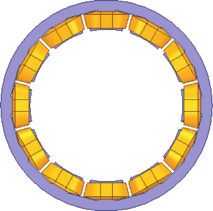
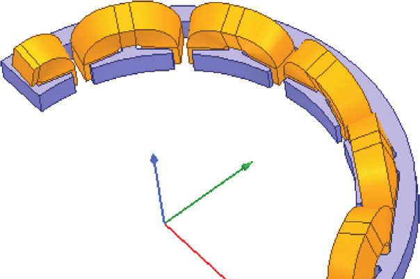
4 Mathematical Problems in Engineering

 ·
 · jId Xad
 jIN Xaq ·
 jIN Xaq

 · ·
 E aq
 ·
 Ed
 ·
 · jIq Xaq
 Ed
 ·
 IN X1
 θ ·
 IN R1
 · ·
 Fd Fd ψK
 · ψ · ·
 Iq · Iq IN X1
 UN
 φ φ
 · · ·
 IN IK IK R1
 · ·
 Id Id

 (a) (b)

Figure 2: Phasor diagram of the stable operation of permanent magnet generator: (a) resistive and inductive load; (b) steady-state short
circuit.

 Stator core Table 1: Slot vector phase diagram.
 1 2 3 4 5 6 7 8 9 10 11 12
 1 +1 +2
 Coil 2 +3 +4
 3 +5 +6
 4 +7
 5 +8 +9
 6 +10 +11
 7 +12
 8 −1
 9 −2 −3
 10 −4 −5
 11 −6
 12 −7 −8
 13 −9 −10
 14 −11 −12
 Figure 3: Fractional slot concentrated wingdings. Phase A B C

faults and enhances fault tolerance [6, 7]; in addition, the denotes that the direction of the current in the coil is op-
large air gap inductance and slot opening magnetic leakage posite to the direction of the coil current with the “+”
of FSCW increases self-inductance, which helps to suppress symbol. The calculation results demonstrated that the pitch-
fault short-circuit current. Based on the technical charac- shortening factor of the fundamental wave winding is 0.966,
teristics and advantages of the abovementioned FSCW and the distribution coefficient of fundamental wave winding is
considering the limited installation space of permanent 0.966, and then the winding coefficient of fundamental wave
magnet generator, the number of pole pairs of the perma- is 0.933. Figure 4(a) shows the three-phase armature
nent magnet generator designed in this paper was selected as winding connection.
np � 7 and the number of stator slots was selected as Z � 12. The number of turns of the coil is mainly determined
Then, the number of slots per pole per phase spp is by the output voltage class of the permanent magnet
 Z 2 generator, and the output voltage is proportional to the
 spp � � . (4) number of turns of the coil. The selection of the wire
 2 · np · 3 7
 diameter of winding mainly depends on the current
 Table 1 displays the phase diagram of the 14p12s slot density under rated condition. The greater the current
vector. The numbers in the figure represent the corre- density, the larger the winding loss, the greater the heat
sponding coil numbers in the slot, and the “−” symbol generated by the winding per unit time, and the larger the
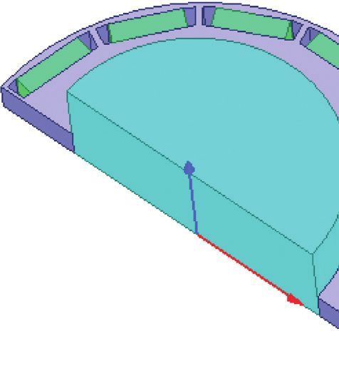
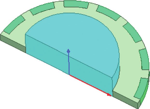
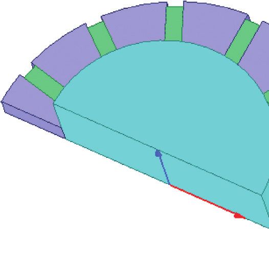
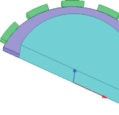
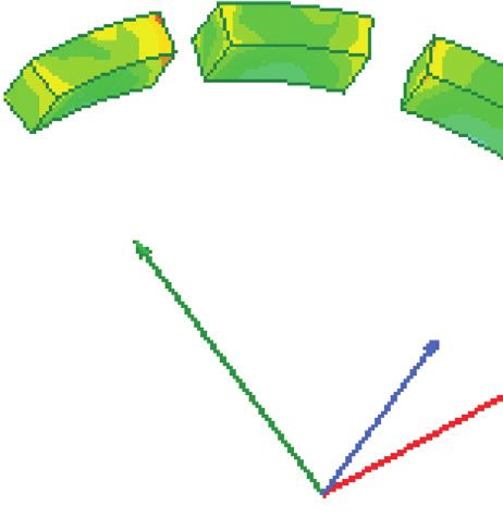
Mathematical Problems in Engineering 5

 4 3
 Z
 5 2 Y
 6 1
 Z
 7 12

 8 11
 9 10

 X

 (a) (b) (c)

 Z
 Z
 Z

 (d) (e) (f )

Figure 4: Distribution of winding of permanent magnet generator and different installation methods of permanent magnet. (a) Armature
winding connection. (b) Stator component. (c) Surface magnet configuration: radially magnetized. (d) Inset magnet configuration: radially
magnetized. (e) Buried magnet configuration: radially magnetized. (f ) Buried magnet configuration: circumferentially magnetized.

impact on the insulation class of the winding and the
 1.2
magnetic properties of the permanent magnet. At the same
time, considering that the permanent magnet generator 1.0
should not be burnt when the winding is short circuited,
the short-circuit current and short-circuit current density 0.8
should be controlled within a safe range [8–10]. In this
 B (T)

 0.6
paper, the multiple of short-circuit current I∗k was required
to be controlled within 2.1. 0.4
 There are various installation methods of permanent
 0.2
magnet. The magnetomotive force and magnetic flux pro-
vided by the permanent magnet to the external magnetic 0.0
circuit vary with different installation forms, which in turn 0 200 400 600 800
has a significant influence on the electromagnetic properties H (kA/m)
of the generator. The common rotor structures of permanent Figure 5: Demagnetization curve of SmCo28H.
magnet generators are shown in Figures 4(c)–4(f ). In order
to obtain the optimal design of the permanent magnet
generator, the electromagnetic properties of four different
 generator is a nonlinear and strong coupling multivariable
rotor structures were analyzed in detail.
 system, it has a complicated electromagnetic relationship.
 In order to avoid permanent demagnetization of the
 Although the finite element calculation can obtain a more
permanent magnet at high temperature and large current, the
 accurate numerical solution, it requires many calculation
permanent magnet material is selected as SmCo28H, whose
 resources, long calculation time, and has low efficiency.
demagnetization curve is a straight line, as shown in Figure 5,
 Therefore, in this paper, the magnetic circuit method and the
and a loop line coincides with it. The Curie temperature of
 design of experiment (DOE) method were adopted to study
SmCo28H is 820°C, and the maximum operating temperature
 the influence of the electromagnetic parameters of the
is 350°C. Other parameters are shown in Table 2.
 permanent magnet generator on the short-circuit current
 and visualized related sensitivity information was provided,
4. Optimized Design thereby saving time cost and enhancing design efficiency.
 This method is especially suitable for optimization design.
Permanent magnet generators need to be designed as high- According to (2), the influence of 10 design variables such as
impedance motors to reduce short-circuit current and im- stator inner diameter (Di1) and stator tooth width
prove the reliability and safety of operation. Since the (Toothwidth) on short-circuit current was explored. Table 3
6 Mathematical Problems in Engineering

 Table 2: Performance parameter of SmCo28H.
Br (T) Hcb (kA/m) Hcj (kA/m) (BH)max (kJ/m3)
1.07 749 1990 215
Curie temperature (°C) Operating temperature (°C) α(Br) (%/°) β(Hcj) (%/°C)
820 350 −0.03 −0.2

 Table 3: Design variables.
Symbol Name Unit Range Physical meanings
P2 Di1 mm 68∼77 Stator inner diameter
P3 Len mm 8∼16 Axial length
P4 Toothwidth mm 2∼3.5 Stator tooth width
P5 hs0 mm 0.8∼2.5 Stator slot opening height
P7 hs2 mm 4∼6.5 Stator slot height
P8 bs0 mm 4∼9 Stator slot opening width
P9 N — 80∼120 Number of turns of coil
P10 Embrace — 0.5∼0.9 Permanent magnet pole-arc coefficient
P11 PM_H mm 2∼5 Magnetizing direction length of permanent magnet
P12 Gap mm 1.5∼3 Length of air gap

exhibits the design variables and their physical meanings, in
 40
which the number of turns of coil (N) is a discrete variable
that can only be a positive integer. 30
 Figure 6 shows a histogram of the sensitivity of the
 Local sensitivity (%)

design variables to the short-circuit current when the 20
number of coil turns N � 95. The greater the sensitivity, the
larger the influence of the design variable on the short- 10
circuit current. Positive sensitivity means that the short-
circuit current increases with the increasing design variable. 0
Negative value means that the short-circuit current de-
creases with the increase of the design variable. It can be –10
found from the analysis of Figure 6 that the dimension
 –20
parameters of the permanent magnet (pole-arc coefficient P13-short circuit current parameter output
and length of magnetizing direction), stator inner diameter, Parameters
air gap length, and depth and width of stator slot opening P1-D1[mm] P2-Di1[mm]
have a great influence on the short-circuit current: P3-Len[mm] P4-Toothwidth[mm]
 P5-hs0[mm] P6-hs1[mm]
 ① The larger the embrace and PM_H, the greater the
 P7-hs2[mm] P8-bs0[mm]
 amount used by permanent magnet, the larger the P10-embrace P11-PM_H[mm]
 magnetic field provided during operation, and the P12-gap[mm]
 greater the corresponding short-circuit current.
 Therefore, under the premise of ensuring the operating Figure 6: Analysis of sensitivity to short-circuit current of the
 point of the permanent magnet, the usage quantity of permanent magnet generator.
 permanent magnet can be appropriately reduced to
 decrease the short-circuit current. the synchronous reactance is proportional to the square
 ② The larger the Di1, the larger the air gap area per of N. Increasing N is also one of the effective measures
 pole, which is equivalent to the increase of the synthetic to improve the high impedance characteristic of the
 permeance of the external magnetic circuit, so that the permanent magnet generator. The magnitude of N also
 short-circuit current also rises accordingly. needs to meet the requirements for coil current density
 ③ The larger the hs0 and bs0, the greater the leakage and stator slot fill factor.
 reactance of the stator slot body, which is beneficial to
 reducing the short-circuit current. 5. Simulation Calculation and
 ④ The larger the gap, the greater the armature reaction
 Experimental Results
 reactance, which helps to improve the high impedance Figure 1 shows that the permanent magnet generator is
 characteristic of the permanent magnet generator. externally connected with three-phase uncontrolled rectified
 ⑤ The number of coil turns N can only be a positive current circuit and a current regulating device and then
 integer. The three-phase induced voltage of the per- provides adjustable exciting current to the ME to adapt to
 manent magnet generator is proportional to N, while changes in the load and speed of the MG, so as to ensure
Mathematical Problems in Engineering 7

stable output voltage. To facilitate analysis, the current
regulating device was not considered in this paper. The
external circuit of the permanent magnet generator is Phase A
 Rd
composed of a three-phase uncontrolled rectifier, resistive Ud

 A
 +
load, a voltmeter, and an ammeter, etc, as shown in Figure 7. Phase B V
 Permanent magnet generator has relatively large length

 A
 –
radius ratio and serious magnetic flux leakage at the winding Phase C A Id
ends, which have a great impact on the electromagnetic

 A
properties. Thus, the three-dimensional finite element
simulation models of permanent magnet generators with
four different rotor structures were established in this paper,
as shown in Figures 4(c)–4(f ), where the parameters of stator
components (stator structural parameters and winding Figure 7: External circuit of the permanent magnet generator.
parameters) are the same as the parameters of the rotor core.
The permanent magnets are installed in different ways, but
their volume is constrained to be the same. Accurate cal-
culation and analysis of electromagnetic properties were Table 4: Leakage coefficients.
conducted. Structure Figure 4(c) Figure 4(d) Figure 4(e) Figure 4(f)
 Table 4 presents the no-load leakage coefficients of the Leakage
permanent magnet generators with four different rotor 1 1.18 1.91 2.18
 coefficient
structures shown in Figures 4(c)–4(f ). The magnetic per-
meability of the permanent magnet is close to that of air.
Figure 4(c) shows the nonsalient pole structure, in which the
quadrature-axis and direct-axis synchronous reactance is
equal, the permanent magnet directly faces the air gap, and 180
the magnetic field generated by the permanent magnet does 150
not have magnetic flux leakage, with a leakage coefficient of 120
1, and the magnetic field of permanent magnet can be fully 90
utilized; Figures 4(d)–4(f ) show the salient pole structures, 60
where the quadrature-axis and direct-axis synchronous 30
 Ea (V)

reactance is not equal. The magnetic field of the permanent 0
magnet forms a magnetic flux leakage path through the iron- –30
core material between the poles. The leakage coefficient is –60
related to the installation method and structure parameters –90
of permanent magnet. The larger the leakage coefficient, the –120
smaller the utilization rate of the magnetic field of the –150
permanent magnet, which will have a great impact on the –180
electromagnetic properties. Figure 8 exhibits the A-phase 0.00 0.30 0.60 0.90 1.20 1.50
 t (ms)
induced voltage curves of the permanent magnet generators
with four structures. The voltage effective value after sta- Fig.4 (c) Fig.4 (d)
bilization is 110.78 V, 100.84 V, 75.32 V, and 82.76 V re- Fig.4 (e) Fig.4 (f)
spectively, and the value mainly depends on the utilization of Figure 8: No-load characteristic curves of the permanent magnet
the magnetic field of the permanent magnet. generator.
 Figures 9 and 10 present the external characteristics and
power characteristic curves of permanent magnet generators
with four structures. Given the same stator components uncontrolled rectified circuit was built based on the external
(stator structure parameters and winding parameters), the circuit shown in Figure 6 to perform related experiments on
voltage and power characteristics of the permanent magnet electromagnetic properties.
generator vary with the rotor structure and also depend on Figures 11 and 12 present the simulation data and ex-
the utilization rate of the magnetic field of permanent perimental data on the external characteristic and power
magnet. The surface-mounted structure shown in characteristic of the surface-mounted permanent magnet
Figure 4(c) has a leakage coefficient of 1, and the magnetic generator. Thanks to the three-dimensional accurate mod-
field of permanent magnet can be fully utilized, exhibiting eling of the permanent magnet generator and the finite
the highest output voltage and maximum output power. element calculation of the electromagnetic properties, the
 In order to enhance the utilization rate of permanent experimental data are basically consistent with the simu-
magnet, increase the power density of permanent magnet lation data. The maximum required value of output power of
generator and ensure the operating reliability, this paper the permanent magnet generator is 386 W, and the maxi-
finally selected the surface-mounted rotor structure shown mum output power in simulation and experiment are 402 W
in Figure 4(c) and fabricated a prototype. The three-phase and 425 W, respectively, which meets the design
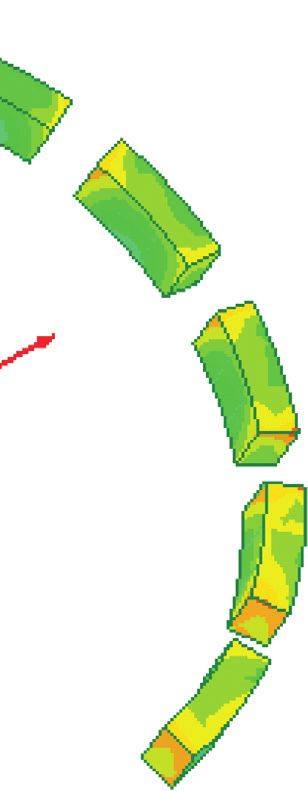
8 Mathematical Problems in Engineering

 300 300

 250
 250
 200
 200

 Ud (V)
 150
 Ud (V)

 150
 100

 100 50

 0
 50 0.00 1.00 2.00 3.00 4.00
 Id (A)
 0
 0.00 1.00 2.00 3.00 4.00 Simulation data
 Id (A) Experimental data

 Fig.4 (c) Fig.4 (d) Figure 11: External characteristic curve.
 Fig.4 (e) Fig.4 (f)
Figure 9: External characteristic curves of the permanent magnet
 500
generator.

 400

 450
 300
 Pd (W)

 400
 350 200
 300
 250 100
 Pd (W)

 200
 0
 150 0.00 1.00 2.00 3.00 4.00
 100 Id (A)
 50 Simulation data
 0 Experimental data
 0.00 1.00 2.00 3.00 4.00 Figure 12: Power characteristic curve.
 Id (A)
 Fig.4 (c) Fig.4 (d)
 Fig.4 (e) Fig.4 (f) generator works in a linear (unsaturated) stage under each
Figure 10: Power characteristic curves of the permanent magnet load. Figures 14 and 15 give the simulation data and ex-
generator. perimental data of the three-phase current of the perma-
 nent magnet generator under the steady-state short-circuit
 condition. The effective value is 2.75 A and 2.7 A, respec-
requirements and leaves sufficient margin to ensure that the tively. The simulation data are relatively consistent with the
permanent magnet generator has enough excitation power experimental data. Under the rated condition, the per-
and driving power under all operating conditions. manent magnet generator needs to output 340 W of power,
 High impedance characteristic (low short-circuit cur- the effective value of the three-phase output current is
rent characteristic) is one of the key design goals of aviation 1.33 A, and the multiple of short-circuit current Ik∗ is about
permanent magnet generator, and increasing the phase 2.03.
winding self-inductance is an effective approach to im- Figure 16 is the cloud diagram of the simulation cal-
prove the high impedance characteristic. In this paper, the culation of the magnetic density distribution of the per-
FSCW was used to increase the number of coil turns. Since manent magnet under the short-circuit condition. The
the self-inductance of the phase winding is proportional to average magnetic density is between 0.7 and 0.8 T. Figure 17
the square of the number of series turns of winding per shows the three-phase no-load voltage curves of the pro-
phase, the impedance characteristic of the generator can be totype before and after the short-circuit test, which are
greatly improved using this method. Figure 13 displays the basically consistent with each other, indicating that, under
variation curve of A-phase self-inductance of the surface- the short-circuit current action of the permanent magnet, no
mounted permanent magnet generator with load current. irreversible demagnetization occurs and the permanent
The change is relatively stable. The permanent magnet magnet generator can still work normally.
Mathematical Problems in Engineering 9

 6.0 B
 (Tesla)
 5.5 1.10
 1.04
 5.0
 0.98 Y
 La (mH)

 4.5 0.93
 Z
 0.87 X
 4.0
 0.81
 3.5 0.75
 0.69
 3.0
 0.63
 0.00 1.00 2.00 3.00 4.00
 Id (A) 0.58
 0.52
 A phase self-induction
 0.46
Figure 13: Variation curve of A-phase self-inductance with load 0.40
current.
 Figure 16: Cloud diagram of magnetic density distribution of
 permanent magnets under short-circuit condition.
 7

 5
 200.0
 3 150.0
 100.0
 1
 IKabc (A)

 50.0
 E0 (V)

 –1 0.0
 –50.0
 –3 –100.0
 –150.0
 –5
 –200.0
 100.7 100.8 100.9 101 101.1 101.2 101.3 101.4 101.5
 –7
 t (ms)
 0 1 2 3 4 5 6 7 8 9 10 11
 t (ms) Before short circuit
 After short circuit
 Ikarms = 2.75A
 IKbrms = 2.76A Figure 17: No-load characteristic curve before and after short
 IKcrms = 2.75A circuit.
Figure 14: Three-phase short-circuit current of the permanent
magnet generator: simulation data.
 6. Conclusion
 The permanent magnet generator is one of the key com-
 ponents of a three-stage electrically excited brushless syn-
 I1 9.000A
 chronous motor, with main function to provide excitation
 I2 9.000A
 power for the main exciter and driving power for the
 I3 9.000A controller. In order to meet the design requirements for its
 power characteristic and high impedance characteristic, this
 paper adopted the fractional slot concentrated winding to
 increase the high impedance characteristic of the permanent
 magnet generator by enhancing the self-inductance of phase
 winding and optimizing the structural parameters, thereby
 reducing the short-circuit current. Then, the electromagnetic
 properties of four common rotor structures of permanent
 I1 –9.000A
 magnet were analyzed in detail. It was found that the per-
 I2 –9.000A
 manent magnet generator with surface-mounted structure
 I3 –9.000A has no magnetic flux leakage, and the magnetic field of
 0 ms 0.5 ms 1 ms 1.5 ms 2 ms permanent magnet can be fully utilized, contributing to its
 greatest capability of power output and highest power
Figure 15: Three-phase short-circuit current of permanent magnet
generator: experimental data. density. Therefore, this paper finally selected the permanent
10 Mathematical Problems in Engineering

magnet generator with surface-mounted structure and
manufactured a prototype to conduct related experiments
on electromagnetic properties. The simulation data are
basically consistent with the experimental data. Its power
characteristic meets the design requirements and leaves
sufficient margin. The three-phase steady-state short-circuit
current is small, about 2.03 times the rated operating cur-
rent. The power characteristic and high impedance char-
acteristic of the permanent magnet generator ensure
reliability and safety of its operation under all operating
conditions.

Data Availability
The raw/processed data required to reproduce these findings
cannot be shared at this time as the data also forms part of an
ongoing study.

Conflicts of Interest
The authors declare that they have no conflicts of interest.

References
 [1] J. Chang, “Outlook of roles and necessities of power elec-
 tronics for vf-power systems of future large aircraft,” in
 Proceedings of the International Conference on Electrical
 Machines and Systems, pp. 1190–1195, Wuhan, China, Oc-
 tober 2008.
 [2] J. Chang and A. Wang, “New VF-power system architecture
 and evaluation for future aircraft,” IEEE Transactions on
 Aerospace and Electronic Systems, vol. 42, no. 2, pp. 527–539,
 2006.
 [3] P. Ma, Starting Control Techniques of Aviation Brushless
 Synchronous Integated Starter/Generator System, North-
 westem Polytechincal University, Xi’an, China, 2016.
 [4] Z. Zhang, J. Huang, Y. Jiang, W. Geng, and Y. Xu, “ Overview
 and analysis of PM starter/generator for aircraft electrical
 power system,” CES TEMS, vol. 1, no. 2, pp. 117–131, 2017.
 [5] R. Tang, Modern Permanent Magnet Machines Theory and
 Design, pp. 289-290, China Machine Press, Beijing, China,
 2017.
 [6] C. Gerada, K. Bradley, and M. Summer, “Winding turn-to-
 turn faults in permanent magnet synchronous machine
 drives,” in Proceedings of the Fourtieth IAS Annual Meeting.
 Conference Record of the 2005 Industry Applications Confer-
 ence, pp. 1029–1036, Hong Kong, China, October 2005.
 [7] L. EL-Refaie, J.-R. Riba Ruiz, and A. Garcia Espinosa,
 “Fractional-slot concentrated-windings synchronous perma-
 nent magnet machines: opportunities and challenges,” IEEE
 Transactions on Industrial Electronics, vol. 57, no. 9, 2012.
 [8] A. Romeral, O. A. Urresty, R. J. C. Riba et al., “Modeling of
 surface-mounted permanent magnet synchronous motors
 with stator winding inter-turn faults,” IEEE Transactions on
 Industrial Electronics, vol. 58, no. 5, p. 1576, 2011.
 [9] M. Fitouri, Y. Bensalem, and M. N. Abdelkrim, “Modeling
 and detection of the short-circuit fault in PMSM using finite
 element analysis,” Ifac Papersonline, vol. 3, pp. 566–569, 2013.
[10] P. Arumugam, “Design optimization on conductor placement
 in the slot of permanent magnet machines to restrict turn-turn
 short-circuit fault current,” IEEE Transactions on Magnetics,
 vol. 52, no. 5, Article ID 2516504, 2016.
You can also read