Development of an Interactive 3-D Virtual Environment Test Bed For Motorbikes
←
→
Page content transcription
If your browser does not render page correctly, please read the page content below
Development of an Interactive
      3-D Virtual Environment Test Bed
               For Motorbikes

                                     Paul Ashaolu

                                    Bachelor’s Thesis

                 ___. ___. ______   ________________________________

Valitse kohde.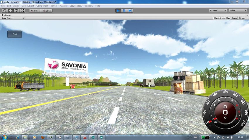
SAVONIA UNIVERSITY OF APPLIED SCIENCES                                             THESIS
                                                                                   Abstract

Field of Study
Engineering and Technology
Degree Programme
Information Technology
Author(s)
Paul Ashaolu
Title of Thesis
Development of an Interactive 3-D Virtual Environment Test Bed for Motorbikes
Date              8 May 2012                       Pages/Appendices         53+6
Supervisor(s)
Dr. Topi Kallinen, Principal Lecturer
Client Organization/Partners
Electrical and Information Technology Research Unit, Savonia University of Applied Sciences
Abstract
           The Virtual world and environment technology is rapidly being deployed for effective
           visual representation of simulations which enables users to interact and explore the
           environment and even conduct tests. The technology has also effectively provided safe
           ways to review and modify designs, and even train users on the use of different
           systems. This final project was commissioned by the Electrical and Information
           Technology Research Unit of Savonia University of Applied Sciences and Lekasteel Oy,
           Finland. The aim of this thesis was to develop a three-dimensional virtual environment
           simulation test bed for motorbikes.

           The prototype of this simulation system was built by equipping a motorbike with sensors
           and interfacing it to an Arduino based embedded systems which implements the rider’s
           equivalent navigation and manipulation in a virtual environment. Unity3D was used as
           the development platform to create the virtual environment, and scripting was done in
           C# and JavaScript. Various tests were carried out on the system at Savonia’s Electrical
           and Information Technology research facility and useful information about simulation
           systems was gathered as a result of the study.

           The prototype system was presented at the Helsinki motorbike exhibition which took
           place at the Helsinki Messukeskus from 2 to 5 February, 2012. Plans are under way to
           improve on the design and develop the system further to provide support for two or
           more riders.

Keywords
Virtual Reality, Virtual environment, 3-D, Arduino, Interactive, Simulation, Unity3D,
Terrain Simulation, USB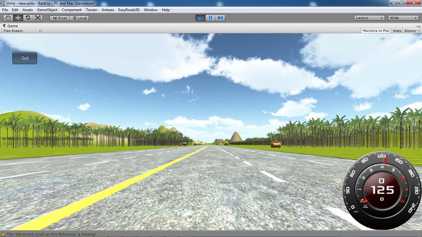
3

Koulutusala
Engineering and Technology
Koulutusohjelma
Information Technology
Tekijä
Paul Ashaolu
Työn nimi
Development of an Interactive 3-D Virtual Environment Test Bed for a Motorbikes
Päiväys         08 May 2012                            Sivumäärä               53+6
Työn valvoja
Dr. Topi Kallinen, Principal Lecturer
Yritys
Electrical and Information Technology Research Unit, Savonia University of Applied Sciences
Lekasteel Oy, Tuusniemi
Abstract
            Virtuaalisen maailman ja ympäristön teknologia muuttuu nopeasti. Testien ja
            interaktiivisten virtuaaliympäristöjen tehokas esittäminen ja kokeileminen on nykyään
            mahdollista. Teknologia mahdollistaa myös tehokkaan ja turvallisen tavan kokeilla ja
            muokata järjestelmän malleja samalla mahdollistaen jopa erilaisia koulutuksia. Tämä
            lopputyö       tehtiin    Savonia-ammattikorkeakoulun     Sähkö-     ja   tietotekniikan
            tutkimusyksikössä. Lopputyö tehtiin yhteistyössä tuusniemeläisen Lekasteel Oy:n
            kanssa.

            Järjestelmän interaktiivinen prototyyppi toteutettiin yhdistämällä moottoripyörä sekä
            Arduino-pohjainen järjestelmä, jolla toteutettiin käyttöliittymä. Käyttöliittymällä
            navigoidaan ja liikutaan virtuaaliympäristössä. Kehitysalustana käytettiin Unity3D-
            ohjelmistoa, jolla tehtiin virtuaaliympäristö; ohjelmointi toteutettiin C#- ja JavaScript -
            kielillä. Järjestelmällä tehtiin useita testejä, joita kerättiin ja käytettiin myöhemmin.
            Testit     toteutettiin    Savonia-ammattikorkeakoulun        Sähkö-    ja     tietotekniikan
            tutkimusyksikössä.

            Prototyyppijärjestelmä esiteltiin Helsingin messukeskuksessa järjestetyssä vuosittaisessa
            moottoripyöränäyttelyssä. Moottoripyöränäyttelyn ajankohta oli 2. ja 5. helmikuuta 2012
            välisenä aikana. Jatkokehityskohteena on kahden kuljettajan yhtäaikainen käyttö

Keywords
Virtual Reality, Virtual environment, 3-D, Arduino, Interactive, Simulation, Unity3D,
Terrain Simulation, USB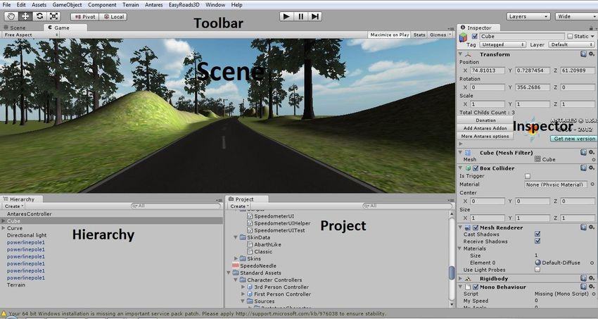
4

Acknowledgements

This project would not have been possible without the guidance and help of several individuals
who contributed and extended their valuable assistance in the preparation and completion of this
study;

My sincere appreciation goes to my supervisor, Dr. Topi Kallinen whose expertise and
understanding encouraged me to shape my interest and ideas. I appreciate his assistance in
writing this thesis and his pain-staking effort in proof-reading the drafts.

I would like to express my deep gratitude to the head of my department, Mr Arto Toppinen, for
giving me an opportunity to be a major part of this development work, and also for providing me
with invaluable insights throughout my degree programme.

A very special thanks goes to Mr Hannu Hoffrén, for his direction and technical support at all levels
of the project development. His friendly help contributed immensely to the success of this project.

Finally, I would like to thank my family who taught me that I can do everything through Christ who
gives me strength, and my friends both in Finland and Nigeria for their support and understanding
throughout my studies at Savonia University of Applied Sciences.

Kuopio, 8 May, 2012
5

TABLE OF CONTENTS

1 INTRODUCTION ............................................................................................. 8
2 INTERACTIVE SIMULATION SYSTEMS .............................................................. 9
   2.1 Overview………………………………………………………………………………………………..9
   2.2 History……………………………………………………………………………………………………9
   2.3 Digital Simulators ..................................................................................... 9
   2.4 Visual Systems ....................................................................................... 10
   2.5 Virtual Reality......................................................................................... 11
         2.5.1 Immersion .................................................................................... 12
         2.5.2 Interaction ................................................................................... 13
         2.5.3 Imagination .................................................................................. 13
   2.6 Virtual Environment Systems ................................................................... 13
   2.7 Virtual Reality Modeling Language (VRML) ................................................ 15
   2.8 Terrain Generation Systems .................................................................... 16
3 PRELIMINARY DEVELOPMENT STUDIES ......................................................... 17
   3.1 The Sensor Module ................................................................................. 19
   3.2 Embedded Systems Module ..................................................................... 20
   3.3 Visualization ........................................................................................... 20
4 TECHNICAL REQUIREMENTS AND IMPLEMENTATION ...................................... 21
   4.1 The Interface Card ................................................................................. 22
   4.2 The Sensor Module ................................................................................. 23
         4.2.1 The Speed Sensor ......................................................................... 23
         4.2.2 Lean Angle Sensor ........................................................................ 25
         4.2.3 Brake Pressure Sensor ................................................................... 27
         4.2.4 The dynamometer brake system .................................................... 28
         4.2.5 Lambda Sensor ............................................................................. 29
   4.3 Embedded Systems ................................................................................ 30
         4.3.1 The Arduino microcontroller ........................................................... 30
         4.3.2 The Arduino Development Environment .......................................... 31
         4.3.3 Arduino Communication Protocol .................................................... 32
   4.4 Visualization ........................................................................................... 34
         4.4.1 Unity3D engine ............................................................................. 34
         4.4.2 Unity3D interface and controls ....................................................... 34
         4.4.3 The Unity3D terrain engine ............................................................ 37
         4.4.4 Realization of the Motorbike and View ............................................ 39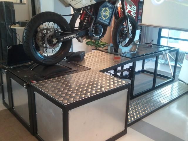
6

5 INTERFACING THE MODULAR UNITS .............................................................. 41
   5.1 Programming Languages and libraries used ............................................... 41
   5.2 System run diagram ................................................................................ 43
   5.3 The Dynamometer Graph......................................................................... 45
   5.4 Dynamometer Calculations....................................................................... 46
6 RESULTS AND EVALUATION ........................................................................... 48
7 CONCLUSION ................................................................................................ 50
REFERENCES..................................................................................................... 51
APPENDIX A: Unity3D Installation and Set up for Serial Communication ................. 53
APPENDIX B: Project’s Time-Plan ........................................................................ 58
7

LIST OF ABBREVIATIONS

2-D       -         Two Dimensional

3-D       -         Three Dimensional

ACL       -         Agent Communication Language

API       -         Application Programming Interface

CGI       -         Computer Generated Imagery

CLI       -         Common Language Infrastructure

CSV       -         Comma Separated Value

DCE       -         Data Circuit-Terminating

DOF       -         Degree of Freedom

DTE       -         Data Terminal Equipment

GIS       -         Geographic Information System

HMD       -         Head Mounted Display

IC        -         Integrated Circuit

IDE       -         Integrated Development Environment

OCX       -         Object Linking and Embedding Control Extension

OPIC      -         Optical Integrated Circuit

PC        -         Personal Computer

RPM       -         Revolution per Minute

UART      -         Universal Asynchronous Receiver/Transmitter

UDOFT     -         Universal Digital Operational Flight Trainer

USB       -         Universal Serial Bus

VE        -         Virtual Environment

VGA       -         Video Graphics Array

VRML      -         Virtual Reality Modeling Language

WWW       -         World Wide Web
8
1 INTRODUCTION
This thesis presents the development of an interactive embedded systems test bed for motorbikes.
It was developed at the Electrical and Information Technology research unit of Savonia University
of Applied Sciences for Lekasteel Oy; a Finnish Motorbike Company located in Tuusniemi,
Finland. The aim of this project is to develop an interactive and immersive three-dimensional (3-D)
virtual environment simulation system that allows navigation and manipulation control for
motorbikes through virtual roads with interactions in the virtual world while providing for necessary
physical quantities involved with rigid bodies in motion. This development work is guided by
studies from exploring the mechanical dynamics of live motorbike systems.
The objective is to develop a generic test bed system that is suitable for testing the performance of
various kinds of motorbikes in motion, and also to allow the tuning of engines easily while ensuring
safe conditions. It can also be used as a basic tool for evaluating the rider’s personal psychological
construction. The development of the system will be divided into modular units, namely the sensor
module, the embedded system and the visualization module. The sensor module will deal with the
setup and configuration of all the sensors involved in the project i.e. P1A50HR OPIC Photo-
interrupter, Lambda sensor, potentiometer etc. The embedded systems will co-ordinate the signal
flow and basic calculations while the visualization module will deal with the resulting graphical
interactions. The visualization consists of a real-time graph developed in Visual Studio.NET 2010,
and a 3-D virtual environment application in which the motorbike drives through. Each of these
modules will then be interfaced together to form a whole system test bed.
The virtual interactions of this system will be viewed by projecting the rendered images onto a big
screen. An advanced method of doing this includes projecting the images on surrounding screens.
In order to realize the goals of this thesis work, several questions have to be considered;
How to model a near-realistic virtual environment to present physics behavior present in
real world like gravity, collision etc.?
How to calculate feedback to the motorbike in order to simulate hill-climbing experience?
What is the minimum angle to which a motorbike can bend before it falls?
How to minimize signal delay from one modular unit to the other?
How to choose the appropriate programming language that suitable for accessing the
computer’s universal serial bus (USB) port?
These are all important factors to consider when planning this project. In order to develop a virtual
3-D environment, a game engine that incorporates various multimedia data into a single platform
has to be used.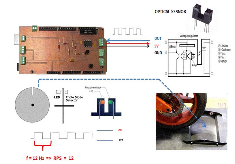
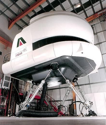
9

2     INTERACTIVE SIMULATION SYSTEMS

2.1    Overview

Interactive simulation systems are models which describe particular system’s processes which are
usually based on physical processes by making use of visual and interactive functionalities of
modern workstation environments. This technique is different from traditional modeling techniques
in which systems are only represented in linear languages and sketched. Simulators are equipped
with functional models of the system they represent or in some cases, spare parts of the system
they emulate. These models or system parts are driven by complex systems of computer-
generated virtual reality engines to bring realistic senses to the user. (Nutt 1988, 1-3)

2.2    History

The first generation simulation systems grew out of a need for training air force pilots without
exposing them to the risks involved. And as such, attempts were made in the early 1900s to
achieve flight experiences by using ground-based trainers which can respond to aerodynamic
forces. Out of those early forms of flight simulators are the Sanders Teacher and Eardley Billings,
which were not so successful at that time due to the irregular nature of wind. (Page 2000, 1-4)

World War I led to increase in demand for flight trainers, and saw improvements in the design and
controls of the simulators. The improvements also made provisions for simulating harsh wind
conditions. Advancements in analogue computers during World War 2 paved way for the
predecessor of modern flight simulators; flight motion calculations were solved using computers
etc. (Page 2000, 5)

2.3    Digital Simulators

Digital simulators rely much on the digital computation powers of modern computers, which had
limited memory capacities at that time and therefore could not be used for real-time flight
equations. In 1950, the University of Pennsylvania led a research aimed at improving the speed
and cost related issues of flight simulations. The University of Pennsylvania’s Universal Digital
Operational Flight Trainer (UDOFT) made it possible to find solutions to aircraft equations of
motion which made real-time simulation possible, and also paved way for improvements to be
made on digital simulators i.e. addition of motion systems to simulations. (Rolfe & Staples 1986,
32-34). Figure 1 shows a picture of the digital flight simulator.

10

FIGURE 1. Digital Flight Simulator (J.M. Rolfe and K.J. Staples 1986)

2.4   Visual Systems

The visual systems gave illusions and perception in simulation systems. The earliest visual system
dates back to the late 1950s. They had only film systems and closed circuit television systems.
Shots from real aircraft were used in the film system, and flight paths were simulated by distorting
the shots from the aircraft to fit into the user's direction. General Electric USA later developed the
first computer image generation (CGI) for simulation systems. They were able to generate ground
plane images with patterns, and later developed the visual systems into full three dimensional
images. (Rolfe et al. 1986, 35)
11

2.5   Virtual Reality

The invention of virtual reality in computer systems dates back to the early 1950s. In 1963, Ivan
Sutherland a researcher at Massachusetts Institute of Technology (MIT) prototyped Sketchpad
program which pioneered the use of graphical user interface in the world of computing. With
Sketchpad, he could use a light pen to draw vector lines on a computer screen. Two years later,
he designed and developed the Head Mounted Display (HMD) and an immersive 3D virtual
environment. His work paved way for opportunities in Human Computer Interaction (HCI) research
work. HCI describes the point at which computer science and human behavioral sciences
intersect. (Shiratuddin, Kitchens & Fletcher 2008, 4)

Virtual reality describes an immersive 3-D virtual environment system which allows a user to
manipulate and navigate through it while the user is experiencing interaction with the virtual
environment rather than the computer (Guo, Fengli & Hong 2010, 1-3). In other words, the virtual
reality system application senses a user’s inputs, and manipulates the virtual scene which is
generated from numerical data, in real-time according to the user's input. This makes the user feel
immersed in the system, and therefore the mind can relate with non-existing things as if they do
exist. (Figure 2.)

FIGURE 2: Block diagram showing the Virtual Reality system
12

Improvements and advances in virtual reality technologies have provided means of allowing
interactive virtual environments (VE) to be implemented on personal computers for interactive
software applications. It can be implemented in various fields e.g. military combat trainings,
surgery and medical diagnosis, games industry etc. The three main functional components of
virtual reality as described by Burdea and Coiffet 2003 is shown in Figure 3.

FIGURE 3. Components of Virtual Reality
(Burdea et al. 2003)

2.5.1   Immersion

Immersion describes a state of been engrossed into a virtual system thereby causing the
consciousness of the real word to diminish as the user respond to stimuli presented by this virtual
system. Immersive virtual reality systems makes use of its basic controls from human responses
i.e. for a user to view an object sideways, the user has to physically turn the face sideways. The
rendering and animating of images in real-time provides a sense of immersion and increases the
rider’s presence. These effects create depth perception and make it possible to have effects which
are present in real world. Further development work on this can help in training purposes.
Furthermore, the visualization engine was made sure to render high quality images accordingly i.e.
to amount to the rider's speed. (Shiratuddin et al. 2008, 5-9)
13

2.5.2    Interaction

Interaction is defined as the ability of a user to physically initiate actions that lead to movements in
a virtual world. It also describes the level of responses virtual objects give in reactions to actions
initiated by the user. Everything associated with input reads from the user which is applied to
constructing display changes in the virtual environment. (Shiratuddin et al. 2008, 5-9)

2.5.3    Imagination

Imagination describes the mind’s capacity to perceive a world or environment that does not exist
i.e. creating and placing non-existing objects. It gives meaning and understandable knowledge
about virtual reality experiences. (Shiratuddin et al. 2008, 5-9)

2.6     Virtual Environment Systems

These systems use interactive three dimensional virtual images, generated from geometrical data
that give users the experience of immersion as they navigate through it. It is mainly characterized
by stimuli or sensory modalities which cause direct interaction with the objects in the virtual
system. This enables a user to integrate physical surroundings with the elements in the virtual
system in real-time. It is very important for a VE system to feel realistic and immersive as much as
possible. At the development level in VE systems, all the entities are modeled to point to realism.
The navigation software interprets gestures from the input device and applies it into processing
movements. This is made possible by mapping particular gestures into known familiar motions e.g.
the forward key on the QWERTY keyboard can be mapped to an object’s direction in the z-axis.
Collisions can also detected by making the VE system search constantly for objects which might
be occupying the same location in 3D-space, and therefore uses the physics engine to calculate
the reactions that could occur from these collisions. (Fisher 1991, 1-6)

Virtual environment data types can be categorized according to the details of the virtual entity it
represents in the virtual environment. Figure 4 shows an example of a virtual environment
developed from three different categories of data types in the virtual environment, namely;
graphical, functional and measurement data type.
14

FIGURE4. The data types to create an immersive virtual environment (Lecakes Jr.,Morris,
Schmalzel and Mandayam 2008, 2)

The graphical data consist of the geometric information of the objects which are presented as
physical objects in the virtual environment by two or three-dimensional spatial objects similar to the
real objects they represent. Their geometric data structures consist of polygons, b-splines, sub-
divisional surfaces etc., and they are rendered along with other different materials to determine
interactivity with light. This contributes to the main idea and creation of illusion in the virtual world.
Measurement data on other hand are signal information from the sensors. Functional data are
entities created through analysis of all graphical and measurement data. Examples include the
simulation or mathematical models created from the combination of the graphical data and raw
information from the sensors. (Lecakes Jr.,Morris, Schmalzel and Mandayam 2008, 2)

Virtual environments can either be single or multi-user. In the single-user mode, users can only
interact with the environments and objects in the environment, but not with other users exploring
the same virtual environment. In the multi-user mode, the users, also known as avatars can
interact with the virtual environment and also with other users or avatars present in the virtual
environment. Interactivity between avatars in multi-user virtual environments helps promote
collaboration in achieving tasks. The architecture of a collaborative multi-user virtual environment
is usually based on the client/server model in which a node coordinates the connectivity issues
and activities of the whole virtual environment. This kind of architecture fits into a good method of
using Virtual Reality Modeling Language (VRML) to develop a web-based virtual learning space
for a distributed learning virtual environment. (S. Burga, S. Tanasă and M. Brut 2002, 45-51)
15

2.7   Virtual Reality Modeling Language (VRML)

The Virtual Reality Modeling Language (VRML) is a platform-independent descriptive language for
interactive 3-D graphics particularly developed for the World Wide Web (WWW). The 3-D models
are made up of polygons with dynamic functionalities and behaviours. VRML presents 3-D worlds
to users in two dimension (2-D) screens as vector graphics, in which the world view is constantly
recalculated and presented to the user as the user changes the vantage point (Liu, Luo, Zhu and
Xiong 2009, 1-4). The VRML files are text-based, defined inside nodes and they describe virtual
models using standard syntax. Figure 5 shows an example of a cylinder node with well-defined
geometrical properties such as height, radius, side, bottom and top;

             Cylinder                                                  +y
             {
                   height 3.5                                                 2.0
                   radius 2.0
                   side TRUE                          3.5                                   +x
                   bottom TRUE
                   top TRUE
             }

Figure 5: An example of a VRML-based Cylinder node

VRML-based virtual environments are commonly deployed in web-based multi user games and
collaborative virtual environments. An example is a VRML-based multiplayer soccer game. The
virtual soccer players are all connected from different human users except the goal keepers which
are autonomous agents and are developed not to go against the rules of the game. The soccer
players are allocated roles and programmed to retrieve information about their current positions
relative to the soccer ball, the goal area and other agents in the distributed environment. The
soccer players then make decision or act based on these informations. Agent communication
language (ACL) is used to develop the game protocol and coordinates how messages are
processed in the multiplayer gaming environment. (Huang, Eliens and Visser 2002, 1-7)
16 2.8 Terrain Generation Systems There are different kinds of terrain generation systems. And what they actually do is to create elevation values over a grid in such a way that the final model resembles the surface of the earth. Some methods of terrain generation includes sculpting techniques, geographic information system based techniques and procedural techniques. (Ong, Saunders and Leggett 2005, 2) Sculpturing involves using modeling software e.g. Maya, 3D Max etc. to manually draw the terrain. Although it is time consuming, it gives a user the ability to create the terrain to the user's skills and also grants the user the total control over the terrain details i.e. it is dependent on the skill of the user. Meanwhile, GIS-based techniques are based on creating terrains from geographic data of actual locations, and using special software to model and render it into similar terrains having the same measurements. GIS measurements can be gotten from satellite images, land surveys etc. Google Earth is a good source to extract geographical data for free. The Procedural technique on the other hand is done by using computer programs to generate terrains which resemble the earth, and the entities associated with it such as erosion, tectonics etc. This technique is usually faster and much easier to use than the rest. Thereby, it is more popularly deployed in games industry. An example of such is the Unity3D game engine, which is a game engine with embedded terrain engine system (Figure 6). FIGURE 6: Unity3d terrain generation (Source: Education Scotland, UK)
17

3   PRELIMINARY DEVELOPMENT STUDIES

There are several simulators for different kinds of vehicles, and these simulators are usually built
with controls to resemble the model of the vehicle and its environment. User inputs are fed into the
simulator engine, which computes the state and updates the virtual environment. In advanced
cases, there are provisions for restricted movements on the seat platform which gives the user a
feeling of immersion (Scherfgen 2008, 2). Earlier work in motorcycle models as described by Prof.
Robin S. Sharp in 1971 suggests a model consisting of two rigid bodies that are joined together
through a conventional steering joint and two wheels. This model investigates the stability and
sensitivity of the motorcycle to geometrical and pneumatic variations. (R.S. Sharp, 1971)

Figure 7 presents a model of a motorcycle with the six body-system and 11 degrees of freedom
(DOF). The bodies include the front and rear wheels, the front and rear assemblies, the rear arm
and the front mass. The rider is seated on the rear assembly and the front and rear assemblies are
connected together by the steering mechanism. The 11 DOF is shown as labeled in Figure 7.

FIGURE 7. Motorcycle model with eleven degrees of freedom (Bortoluzzi, Doria, Lot 2002)
18

This thesis is guided by studies from exploring the mechanical dynamics of a live motorbike. The
motorbike simulation test bed development is modular i.e. the development process is separated
into three modular units, with each module having its own independent task; the sensor module,
the embedded systems and the visualization module. This architecture allows each modules of the
system to be developed and tested individually thereby making the development faster. Also, by
breaking up the process into modular units, each module only needs to be modified if need be,
rather than having to change or modify the entire system which increases the chance of human
errors due to the workflow as illustrated in Figure 8.

FIGURE 8. Workflow of the motorbike simulation modular units
19

3.1   The Sensor Module

This module consists of all the essential components that read and transform physical
characteristic quantities of the motorbike system into output signals. The output signal is mostly
electrical signal. The kinetic quantities to be measured in real-time are listed as shown in Table 1.

Table 1: Quantity measurements
Quantity                                            Sensor
Rear wheel Velocity                                 Photo-interrupter
Lean angle                                          Potentiometer
Engine RPM                                          Lambda Sensor
Brake Pressure                                      Pressure sensor

The quantities have basic measurement according to the features that are needed in the
simulation system. For example, the requirements to consider in measuring the lean angle
according to the design (see Figure 9) is listed below:

1. The system shall have an absolute tracking of the lean angle between +20º to -20º
2. The system's speed shall be accurate to within ±0.065
3. The system shall track motion in three dimensions i.e. x, y and z-axes.

FIGURE 9: Lean angle (Seiniger, Schröter and Gail 2012)
20

3.2   Embedded Systems Module

This module handles the processing of output sensor data from the sensors by the microcontroller
unit at a specified speed and sends results as streams to the PC for calculating states in the
visualization software. It also drives the other module and ensures consistency in the signal
workflow. Delays are minimized as much as possible, and error checking is also done in this to
ensure that the right data format is delivered from end to end.

3.3   Visualization

This module interprets interactions and displays data values sent from the embedded systems
into coordinate system transformations for two-and three-dimensional graphical elements which
have the right quantity of abstraction, and are mapped onto a two-dimensional display i.e.
projected screen. The visualization occurs at run-time i.e. during program execution, and sends
back appropriate feedbacks over specific situations. An example is the visualization of the
scenario whereby a rider accelerates on a race track. The visualization module can also include
visual analysis and graphs which present the drive cycle of the motorbike.

The road track in the virtual world should be modeled to be photographically realistic, with texture-
mapped images of highways and motorways depending on the scene selection. The lighting
should be suitably calibrated using an ambient lighting model e.g. directional lighting, to resemble
ambient weather conditions. The main testing with live motorbikes will be carried out at Lekasteel
facility in Tuusiniemi. All the motorbike's motion and control measures will be recorded for data
analysis. Videos will also be taken for further analysis of the manipulation and navigation
techniques of the motorbike in the virtual world.

Realistic interactions in the virtual environment rely on the system of flow of data between the
modules. Fast refresh rates, accurate collision detection and rapid data transfer is required to
provide realistic interactivity for the user.
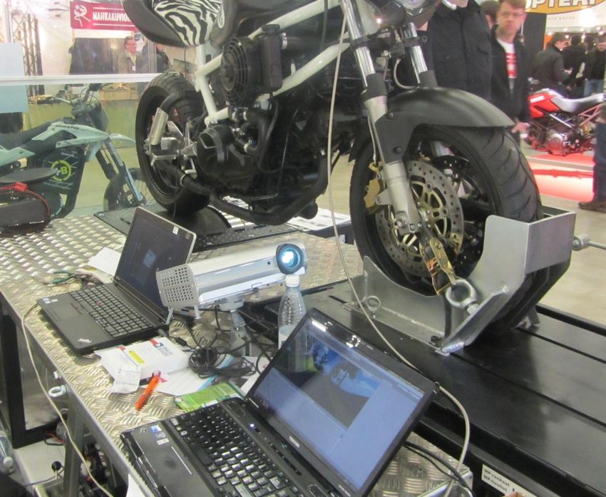
21

4   TECHNICAL REQUIREMENTS AND IMPLEMENTATION

According to Figure 10, the motorbike simulation test bed consists of a standard personal
computer (PC), Intel Core i5 CPU with 4 GB of RAM and NVIDIA graphics card. Also, it includes
sensors which measure the required quantities, a braking system and a graphical display of the
simulation system’s user interface and virtual environment. The PC runs the visualization software
that renders all the graphics present in the virtual environment. The PC is connected to a digital
projector to display it on a screen with a VGA output resolution of 1280x1024 as shown in Figure
10. The motorbike itself is clamped to a mechanical bench that allows some inertial effects.

FIGURE 10. The central processing unit of the system (Photograph: Ashaolu 2012)
22

FIGURE12: Motorbike mounted on the mechanical bench platform (Photograph: Ashaolu 2012)
.

The mechanical bench was constructed by Lekasteel Oy at the company’s facility located in
Tuusiniemi, Finland. The platform consists of wheels located under the bench towards the rear
end and adequate braking systems that supports the rear wheel. According to the Figure 11, the
motorbike is immobilized on the platform by using the front clamp to fasten the front wheel of the
motorbike to the mechanical platform.

4.1   The Interface Card

The interface card is a printed circuit board as shown in the Figure 13, which provides an interface
between the sensors and the microcontroller. The sensors will be connected to the microcontroller
via the interface card. The interface card was designed using the Eagle printed circuit board
design software.
23

                                                                            Interface Card

                                                                             Arduino microcontroller

(a)

(b)

FIGURE 13. The interface card (Photograph: B.Polat)
(a) Side view of the interface card
(b) Aerial view of the interface card

4.2     The Sensor Module

4.2.1    The Speed Sensor

The speed sensor measures the speed of the motorbike by counting the number of turns the rear
wheel makes in one minute. It was constructed from a GP1A50HR Optical integrated circuit
(OPIC) photo-interrupter (see Figure 15). The principle of measurement of the speed sensor is
based on the operation of a photo-interrupter which is mostly made up of two major parts; an
infrared emitter and an infrared detector, both standing uprightly separated from each other in a
"U" shape. These two parts are arranged in such a way that infrared light can shine across the "U"
24
ends, onto the detector and they can detect object whenever it passes in between the emitter and
the detector i.e. breaking the beam of infrared lights. The GP1A50HR Optical IC photo-interrupter
has a slit width of 0.5mm, and it is suitable for measuring rotations of slotted wheels or discs. The
OPIC generates an interrupt whenever it is able to shine through to the photo-transistor. The disc
is placed in between the “U” shape of the photo-interrupter, and whenever the disc rotates to the
slit point, an interrupt is generated. This technique offers a simple and cost-effective method of
counting and measuring the rotation of the motorbike wheel, which on contact with the wheel of
the mechanical platform, drives it and subsequently drives the attached slotted disc. (See Figure
14)
(a)
(b)
FIGURE 14. The OPIC opto sensor point of attachment to the mechanical platform
(a) Magnified image of the slotted disc and the OPIC opto sensor
(b) The OPIC opto sensor positioned at the tip of the slotted disc to measure the RPM of the
wheel25 FIGURE 15. Speed measurement by using the GP1A50HR OPIC photo-interrupter (Polat 2012) Figure 15 shows an illustration of the measurement method at a frequency of 12Hz, and supply voltage of 5V to the OPIC opto sensor. 4.2.2 Lean Angle Sensor The lean angle sensor is composed of a potentiometer. A potentiometer is an electro-mechanical transducer that converts linear or rotary motion from the operator into variations of resistance values. This can be used as a tilt sensor by wiring its outputs to the arduino analog pins. The angle sensor requires a high precision in order to accurately count turns of axle. The operating principle is based on potentiometry; a linear change in angle from 0 to 180 degrees. The resistance on both sides of the wiper varies as a function of the angle of rotation i.e. by simply turning the shaft of the potentiometer.
26

FIGURE 16. Calibration of the lean angle measurement

According to figure 16, the turning effects from 0º to ±90º relatively changes the degree of
closeness of the pin to the 5V supply voltage and 0V ground voltage, to give different outputs; 0 to
1023. This sensor was installed by mounting the sensor housing to a fixed base, and coupling the
rotating shaft to the rotating element.

   (a)                                                     (b)

FIGURE 17. Lean angle sensor installation. (a) Potentiometer at the point of attachment to the
mechanical platform. (b) Orientation of the potentiometer in the x-y coordinates.
27

According to figure 17 (a), the area marked in red colour shows the potentiometer at the point of
attachment to the tip of the mechanical platform. The potentiometer was installed in such a way
that the turning effect of the motorbike on the bench turns the rotating shaft of the potentiometer
and therefore measures the lean angle of the motorbike in the x-y coordinates. This can be further
developed to correspond to the allowed lean angle at specific speeds, to emulate real life
situations.

4.2.3   Brake Pressure Sensor

The MSP 300-2k5-P-4-N-1 pressure sensor was used to substitute a brake pressure sensor
which was difficult to acquire at the time of the thesis work, and a suitable alternative had to be
estimated. The brake pressure sensor was included as a dependent variable needed to avoid
collisions in critical situations by slowing down the speed of the motorbike. The MSP 300 pressure
sensor gave satisfactory measurements at the transducer’s supply voltages between 5V to 30V,
and output voltage signals between 1V to 5V. The sensor pressure ranges between 0 to 170bar,
whereas the motorbike’s pressure ranges between 0 to 60bar. Figure 18 below shows the
connection to the interface card.

FIGURE 18. The Brake pressure sensor
28

4.2.4   The dynamometer brake system

The dynamometer brake used is an electromagnetic brake (Eddy brake current), and it reduces
the speed subsequently during simulation in order to withstand the 400kg mass of the fly wheel.
The pressure sensor controls the brake by measuring the pressure of the brake fluid line. This is a
prototype, so therefore the air resistance factor and the angle variations which ensure a more
precise measurement are not taken into account. The power is rated at 400kW and controlled by
192V direct current. Figure 19 shows a picture of the setup and a block diagram of the setup.

FIGURE 19. Set up of the dynamometer brake system
29

4.2.5   Lambda Sensor

Lambda sensor measures the oxygen and lambda values of the motorbike’s engine. The sensor is
of the type Bosch LSU 4.2, a dual planar ZrO2 current sensor with an integrated heater. The
output ranges between 0 to 5v, and it can be easily mounted on the exhaust pipe. It was calibrated
in volts. Figure 20 shows the wiring of the sensor module

FIGURE 20. Lambda sensor and the controller
30

4.3     Embedded Systems

4.3.1    The Arduino microcontroller

An Arduino microcontroller is an open source programmable hardware, in which the onboard
microcontroller is programmed using the Arduino programming language called Wiring, an open
source programing language for microcontrollers. The Arduino core libraries are written in C and
C++ programming language, and compiled using the avr-gcc and the AVR Libc. The development
environment (IDE) is written in Java and it is based on Processing development environment.
Both the programming environment and the bootloader are freely distributed, and also the printed
circuit boards reference designs (Eagle CAD), is distributed under a Creative Commons Attribution
Share-Alike License thereby making it an open source platform for both personal and commercial
customized designs.

FIGURE 21. An Arduino MEGA board (Arduino Microcontroller)

Arduino board interacts with the environment by taking inputs from sensors and switches,
controlling different types of lights, motors etc. Some common examples of Arduino boards include
Arduino Uno, Ardunio Duemilanove, Lilypad Arduino and the Arduino Mega which was used in this
thesis work. The Arduino Mega is equipped with an ATmega1280 microprocessor, 16 analog
inputs, 54 digital input/output pins which can be specified using the              pinMode(),
digitalWrite() and digitalRead() and operating at 5 volts, while providing or receiving a
maximum of 40 mA, and internal pull-up resistor of 20kΩ - 50kΩ. The analog inputs provide 1024
different values, while measuring from ground to 5 volts Table 2 gives a summary of Arduino
Mega:
31

Table 2. The Arduino Mega

Microcontroller                         ATmega1280
Operating Voltage                       5V
Input Voltage (recommended)             7-12V
Input Voltage (limits)                  6-20V
DC Current per I/O Pin                  40 mA
DC Current for 3.3V Pin                 50 mA
Flash Memory                            128 KB of which 4 KB used by bootloader

4.3.2   The Arduino Development Environment

         FIGURE 22. Arduino development environment
32
In Figure 22, an Arduino development environment includes a toolbar, series of menus, a text
editor and a command line console. Codes written in Arduino are called sketches, and have the
file extension .ino. The Arduino IDE uses command line tools to compile and upload source codes
to the microcontroller. During source code compilation process, the IDE checks the size of the
source codes against the available memory in the microcontroller. If the source code is larger than
the available memory, it flags an error message in the console. The Arduino platform is available
for Windows, Linux and OS X platforms
4.3.3 Arduino Communication Protocol
The use of a single wire to transfer data is known as Serial communication. Parallel
communication on the other hand involves using group of wires to transfer data simultaneously.
The standard of serial communication is the RS-232, which is a set of standards for serial binary
single-ended data between Data Terminal Equipment (DTE) and Data Circuit-terminating
Equipment (DCE). The hardware connection can either be an RS 232 port or the universal serial
bus. Arduino microcontroller board supports serial communication through its RS232 serial port, a
Universal Asynchronous Receiver/Transmitter (UART). A UART is a microchip with programming
that changes data between parallel and serial forms. It communicates directly with a host PC or
other devices for both data acquision and control. The Virtual COM port drivers which are included
in the Arduino board installation files, convert the USB connection on the PC into COM port for file
transfer using the standard serial communication (RS232 interface). It also has the digital pins
0(RX) and 1 (TX) which can be used to connect serial interfaced wires into Arduino. The Arduino
programming language comes with serial application programming interfaces (API) which are
contained in the serial library. Table 3 below highlights some of these common functions:
Table 3. Arduino programming serial functions
Function Description
Serial.begin() Sets the baud rate for data transmission
Serial.available() Gets the number of bytes available for reading over the serial port
Serial.read() Reads the first byte from incoming serial data
Serial.print() Prints data to the serial port
Serial.println() Prints data to the serial port followed by a carriage return character
and a newline
Serial.write() Writes binary data to the serial port
Serial.flush() Flush the buffer of incoming serial data
Serial.end() Terminates serial communication33
Data is sent over the serial port through the Serial object at a certain baud (rate of data), usually
9600. The println() and print() methods are used to print data to the serial port. The
following example prints “Hello world” to the serial monitor.
void setup()
{
Serial.begin(9600);
Serial.println("Hello world!");
}
Receiving incoming data also requires a similar process. The Serial.available() method is
used inside the loop() method to check if any serial data has arrived. The received data is stored
in a variable i.e.
int MyData = 0; // for incoming serial data
void setup()
{
Serial.begin(9600); //opens serial port, 9600kps data rate
}
void loop()
{
// send data only when you receive data:
if (Serial.available() > 0)
{
// read the incoming byte:
MyData = Serial.read();
Serial.print("Received is: ");
Serial.println(MyData, DEC);
}
}
The Arduino collects the data from the sensors at given time intervals, which is determined by the
given sample rate of the arduino microcontroller. For example, a sample data rate of 500 a second
from the OPIC photo-interrupter will give 500 voltage values every second from the
photointerrupter.34 4.4 Visualization 4.4.1 Unity3D engine This section discusses the development of the visualization of the motorbike simulator using Unity3D, a game engineengine. The virtual environment with the roads and road objects was developed in the Unity3D engine development tool. Unity3D is cross-platform game engine software. It supports three scripting languages which are open-source Mono framework; C#, JavaScript and Boo (a dialect of Python). Unity3D also supports varieties of assests including animations, textures, sounds and allows imports of 3D models created in Maya, 3D Max, Blender etc. A custom rendering engine is combined with nVidia PhysX physics engine to render real-time graphics and perform collision detection and response to the virtual environment. The physics engine properties gives mass, drag, collision detection etc. to objects By interfacing the embedded systems with the virtual environment, the motorbike control data can be used to accelerate and steer a rigid body in the virtual environment . The user’s input from the sensors correlates with the throttle of the virtual game object representing the motorbike. 4.4.2 Unity3D interface and controls FIGURE 23. Unity3D Editor
35

The interface is made up of five tabbed windows; Hierarchy, Inspector, Game, Scene and the
Project as seen in Figure 23.

The hierarchy lists all the game objects in the current scene, usually in a tree form that shows the
relationships existing between the game objects. Figure 24 shows the motorbike game object
parenting the camera game object and the camera object inherits properties of the motorbike
object i.e. speed, rigid body etc. Parenting in Unity describes a concept of objects when dragged
into a desired parent object; the dragged object becomes a child object and inherits the movement
and rotation of its parent (unity.com).

FIGURE 24. Hierarchy tab arranging objects according to the relationships

The relationship between the motorbike and camera object was needed to give the rider a feeling
of perception and immersion. For example, as the motorbike experiences slight vibrations on
rough terrains or due to collisions, slight vibrations are also perceived in the rider’s view (camera).
36

   (a)                                                    (b)

FIGURE 25. Inspector window
   (a) Shows the transformation of the selected Motorbike game object, in the world axes
   (b) Shows the attached scripts

The inspector shows a detail list of all components and values of the selected game objects in the
scene. It also shows the scripts attached to the objects. Figure 25 shows the inspector window of
the motorbike, listing the transformation and rotation values. The motorbike object has three
scripts attached to it. The Control signal script is a c# script which handles the collection of digital
signals from the embedded systems, and applies it to the motorbike object. The Down force
written in c# makes sure the motorbike is always in contact with the ground (Y-position = 1), and
applies a downward pull force whenever the motorbike jumps from a cliff. This prevents the
motorbike object from flying.

FIGURE 26. Project files in the asset folder
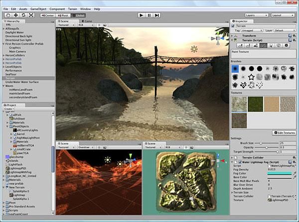
37

The project window shows all the files in the project’s asset folder, including the imported models,
textures and materials. The road materials and buildings in the scene were modelled in Blender,
an open source and exported as .fbx into Unity’s project files. From there, they can be used in the
scene. The Scene window presents a view in which game objects are positioned and manipulated.
It functions as the interactive sandbox.

4.4.3    The Unity3D terrain engine

The Unity terrain engine consists of an editor and tools located in the editor which were used to
create realistic terrains and highways with three dimensional urban environment objects. Although,
it is also possible to import terrains from an external program into Unity3D, but there are limitations
of tree painting and lighting.

   (a)                                                  (b)

FIGURE 27. (a) Terrain without textures          (b) 2-D terrain textures

The terrain for this thesis work was created in the terrain engine by constructing a regular mesh
with the resolution height map set to fit to an oval track. The height map describes the greyscale
map in which the pixel values specify the height of the vertex in the terrain. Two dimensional
textures as seen in figure were applied to the terrain mesh to make it visually realistic. Blended
38

textures were applied to the natural objects in the terrain to obtain the desired landscape of hills
and low-lands. Trees created with the Unity tree creator were also massively placed in the terrain,
and rendered in-game(refer to figure ). Unity3D engine renders trees near the camera in full three
dimensions, and far ones as two dimensional billboards. By so doing, many trees can be rendered
without any significant performance hit.

FIGURE 29: Trees in the Unity3D engine, and mass placement

The track was modelled to be oval in shape with dimensions of 10km x 5km. Unity3D is not
modelling software, so the track had to be modelled in 3DMax, a 3-D modelling tool, and imported
as FBX file extension into Unity3D. Road templates were added on the road model to make it look
realistic.

FIGURE 29. Sketch of the oval track with its dimension
39

FIGURE 30. Modelled road track with template

4.4.4   Realization of the Motorbike and View

Simulating a motorbike system in a virtual environment conventionally would require modelling
every single unit of the motorbike in a 3D modelling package like Blender, 3DMax etc. In addition,
certain units of the motorbike system will require colliders for example the wheels would need
wheel colliders in order to stand upright on the road. But this prototype work only requires the view
from the rider. In this case, the whole view of the motorbike is not taken into account. Only the
driver’s view and the physical behaviour of the motorbike were needed.

The motorbike was modelled after a cubic rigid body. Box colliders were added to enable collision
with other rigid bodies.

FIGURE 31. 3-D object with colliders
40

FIGURE 32. Camera with the view
41

5     INTERFACING THE MODULAR UNITS

FIGURE 33. Block diagram of the motorbike simulation test bed

The sensor module was interfaced with the Arduino microcontroller via the interface card which
provides connections to the respective ports for each sensor type. Port connections were made
according to information in the Arduino Mega and the ATMEGA 128 datasheet which is freely
available online for download.

5.1    Programming Languages and libraries used

Different programming languages were evaluated to be used for this work, especially for the
visualization. Unity3D engine for example supports three scripting languages namely C#,
JavaScript and Boo. But because of access level to hardware e.g. serial ports, C# was chosen as
the scripting language for Unity3D engine, and also for the dynamometer graph user interface.

C# is an object-oriented programming language that reflects the Common Language Infrastructure
(CLI). Most of the intrinsic types in C# are equivalent to the value-types in the CLI framework. C#
was originally developed by Microsoft and now implemented in the .NET framework as well as in
developing Silverlight applications. C# allows method overloading which is necessary in using one
name to define multiple methods having the same parameters.
42

An example is the Transform.Rotate() method which can be overloaded in different ways to
make the motorbike rotate according to the incoming lean angle measurements ;

void Rotate (float xAngle, float yAngle, float zAngle, Space relativeTo)
void Rotate (Vector3 eulerAngles, Space relativeTo)
void Rotate (Vector3 axis, float angle, Space relativeTo)

(Liberty & Xie, 81-84).

The interface between the virtual environment developed in Unity3d and the embedded systems
developed using the Arduino mega microcontroller, was implemented using the .NET Serial Port
class. This was made possible with Unity3D 3.0 versions and upwards, which comes along with
.NET 2.0. Interfacing a custom hardware with earlier versions of Unity3D would require plugins,
which is only possible in the professional versions of Unity3D. The .NET 2.0 has the
System.IO.Ports namespace, and the SerialPort class within it. The serial port class gives an
intrinsic way of serial communication without the ActiveX OCX control as shown in the figure.

FIGURE 34. Serial communication between the Arduino microcontroller and Unity3D engine

Arduino prints the sensor values as SerialPort variables i.e. streams of string arrays. The
Control.cs scripts attached to the game object in Unity3D parses these streams as floats and sets
the speed and rotation of the motorbike object and also shows it on the speedometer. Opening the
serial port sets the Unity3D program in a listening mode, waiting for data to be read from the set
serial port, COM 4 in this case.
43

Using System.IO.Ports
//Set the port (com8) and the baud rate of 9600
    SerialPort stream = new SerialPort("COM4", 9600);
          void Start ()
          {
                stream.Open();    //Open the Serial Stream
          }
          void Update ()
          {
                string value = stream.ReadLine();
          }

5.2   System run diagram

FIGURE 35. The simulation system run diagram

The main() function which is the core of the whole program passes calls to other functions in the
program. It also serves as the starting point of the program execution by calling the start() function
which opens the COM port. The update() function is also called at every frame. The main()
function retrieves the incoming data from the Arduino microcontroller, via the COM port and calls
the control() function, which is responsible for parsing the string array into velocity and Euler angle.
The program stops execution at the end of the main OnCollision() or whenever the Quit button
is clicked OnMouseEnter(). Below is a pseudo code for the main() function
44
Program Starts
Calls the scene and refreshes it at every frame
While the Quit button not pushed OR no collision
Reads data from arduino microcontroller
Adjust the velocity and rotation of motorbike object
Plots the dynamometer graph
While end
End
Figure 36 gives an illustration of decisions that needs to be made at the start of executing the
virtual environment software.
Start
Speed
Angle Velocity=Speed*transform
EngineRPM
No
Is Speed > 0
-Angle > -0.065 OR
Angle < +0.065
Yes
Rotate=Angle Execution
Checks for Collision
No
Collision?
Quit Button?
Yes
Stop
FIGURE 36. Simulation system flow diagram45
The C# control scripts on the other hand is responsible for parsing and splitting the incoming string
arrays into the velocity and Euler’s angle for the motorbike game object. Below is a sample code:
//split incoming stream values on space into arrays
var values = value.Split(' ')
Speed = float.Parse(values[0]);
Angle = float.Parse(values[1]);
RPM = float.Parse(values[2]);
//Speedometer User interface
SpeedometerUI.Speed = Speed;
SpeedometerUI.RPM= RPM;
rigidbody.velocity = (transform.right*(Speed));
if ( (Angle > 0.0655 || Angle < -0.0655 ) && (mySpeed > 0 ) )
{
transform.Rotate(Vector3.up * Angle);
}
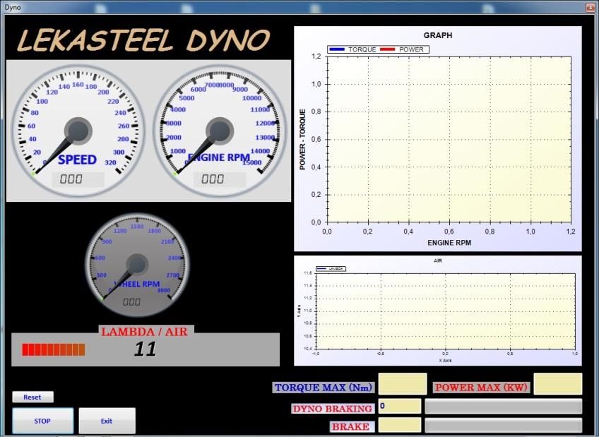
5.3 The Dynamometer Graph
Inertia dynamometer graph plots analyze results of dynamometer testing of vehicles and simulate
the dynamic conditions during acceleration. Needed parameters needed for dynamometer tests
consists of the engine's RPM, torque and power. There are various ways of developing the real-
time graph depending on the development environment. Examples include the LiveGraph, which is
a Java-based framework for developing data visualization plots from comma separated values
(CSV). Other examples include the NPlot, an open source library for .NET framework. (Okedara
2012, 37-44). A sample dynamometer graph is plotted as shown in the Figure 37.
FIGURE37. A sample dynamometer graph (XS Engineering, Inc)You can also read