Development of the BIM Data Repository of Lands Department
←
→
Page content transcription
If your browser does not render page correctly, please read the page content below
Development of the BIM Data Repository of Lands Department

                 Nelson YAM, Hong Kong; Calvin KAM, USA; Min SONG, USA

   Key words: BIM, GIS, Data Repository

   SUMMARY

   The adoption of Building Information Modelling (BIM) and the Creation of 3D digital map
   are part of the Smart City Blueprint of the Hong Kong Government promulgated in 2017.
   All major public works projects need to adopt BIM from 2018 onwards. The Construction
   Industry Council in Hong Kong (CIC) and various government departments in Hong Kong are
   spearheading the drafting of different standard and attempted to harmonised BIM created in
   different phases of a project. With the concerted effort of the stakeholders in the industry,
   there are increasing amount of quality BIM data being generated by government and private
   development projects in Hong Kong. However, those data are difficult to be exploited in a
   broader context for a variety of reasons. The fragmentation in sharing of BIM data; lack of
   standardised BIM data; and the absence of a platform for identifying and accessing the data
   are some of the problems that hindered the sharing of BIM data across government
   departments as well as integration of BIM data with GIS data.

   There are different initiatives taken by the stakeholders and the CIC in standardising and
   harmonising BIM data in different projects following prevailing international standards. In
   2018, in order to assist the sustainable development of 3D digital map and to facilitate spatial
   data sharing, Lands Department (LandsD) implemented a prototype of BIM Data Repository
   (BIM DR) for the uploading, converting and sharing of BIM models in a common 3D GIS
   environment. BIM data uploaded to the prototype BIM DR has been simplified, making it
   easy to be shared in open formats, facilitating land and infrastructure developments. The
   prototype is still up and running with more than 40 projects submitted from participated
   works departments as at March 2021. The successful implementation of a full-scale BIM DR
   to support Open BIM and Open GIS is one of the cornerstones in the sustainable development
   of Digital Hong Kong. It will help the construction and geospatial industries to leverage the
   rich spatial data content of the BIM data for a variety of applications. The data collected in the
   BIM DR will also be an invaluable source of data for future development of 3D digital map in
   LandsD. This paper presents technical options reviewed and adopted in the areas of level of
   development, model simplification and open standard adoption for the development of a full-
   scale BIM Data Repository in LandsD.

Development of the BIM Data Repository of Lands Department (11202)
Nelson Yam (Hong Kong SAR, China), Calvin Kam and Min Song (USA)
FIG e-Working Week 2021
Smart Surveyors for Land and Water Management - Challenges in a New Reality
Virtual, 21–25 June 2021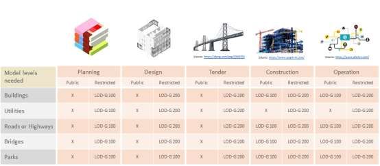
Development of the BIM Data Repository of Lands Department

                 Nelson YAM, Hong Kong; Calvin KAM, USA; Min SONG, USA

       1. Introduction
   With the increasing amount Building Information Modelling (BIM) data becoming available
   to government agencies, opportunities arise for developing a BIM and Geographic
   Information System (GIS) integrated platform, but this requires deeper knowledge of the
   geometric data, the semantics, the level of development (LOD), and the data interoperability
   issues and formats that are heterogeneous between BIM and GIS. Integrating the BIM and
   GIS data with a neutral open format and with an appropriate level of granularity or
   simplification and making them shareable and serviceable on a common platform is by no
   means trivial and requires deeper knowledge of both domains. To join hand with The
   Construction Industry Council in Hong Kong (CIC) and other government departments,
   Lands Department (LandsD) has implemented a prototype of BIM Data Repository (BIM
   DR). In this paper, we present the review of different technical consideration in the design of
   the full scale BIM DR with a view to creating simplified and shareable BIM and GIS,
   including (i) the need of different BIM LODs in supporting requirements of different project
   stages and use cases, (ii) technical approaches in effectively simplifying BIM for the BIM
   DR, and (iii) technical options for adopting open standards-based integration. This paper
   presents preferred and viable options that will be explored and extended in the future.

       2. Project stages and LODs

       2.1 Project Stages
   The technical circular DEVB TC(W) No. 12/2020 issued by the Development Bureau defines
   three stages of a project for categorizing BIM uses: “Investigation, Feasibility and Planning
   Stage,” “Design Stage,” and “Construction Stage.” The BIM uses identified in this technical
   circular focus on BIM uses during the design and construction stages. The BIM DR uses,
   however, extend beyond the construction stage, encompassing the operation stage.
   Accordingly, we have extended the stages for BIM DR into five stages: “Planning,” “Design,”
   “Tender,” “Construction,” and “Operation.”

   a. Planning Stage: This stage corresponds to the “Investigation, Feasibility and Planning
   Stage” in DEVB (2020). This stage involves market analysis, determining the location and
   size of the works, developing employer’s requirements, conceptual design, financial analysis,
   and regulatory analysis. During this stage, BIM may be available, but even if it is available,
   the BIM will be of a low level of development.

   b. Design Stage: According to DEVB (2020), the use of BIM becomes mandatory for projects
   under Design and Construction consultancy agreements (DC) or Investigation, Design and
   Construction consultancy agreements (IDC) and all in-house projects. Buildings Department
   (BD) in Hong Kong also has a plan to leverage BIM submitted to help check plans by 2025.

Development of the BIM Data Repository of Lands Department (11202)
Nelson Yam (Hong Kong SAR, China), Calvin Kam and Min Song (USA)
FIG e-Working Week 2021
Smart Surveyors for Land and Water Management - Challenges in a New Reality
Virtual, 21–25 June 2021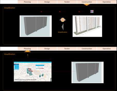
We anticipate that the LOD of BIM available at the end of the Design Stage will be in the
   range of LOD300 to LOD350.

   c. Tender Stage: The BIM associated in a tender package are typically frozen in most projects.
   and should be less susceptible to changes. This stage is not defined in DEVB (2020) as a
   stage, but we considered that this stage mark the availability of a confirmed stable version of
   BIM for the BIM DR since the BIM will be in sufficient detail to enable tenderers to make
   technical and commercial proposals. Projects at this stage are not likely to be cancelled.

   d. Construction Stage: During the Construction Stage, BIM is used for reviewing shop
   drawings, calculations, resources, and overseeing the workmanship of the contractors, among
   others. This stage will mostly involve developing LOD300 elements to LOD350 or LOD400.
   At the end of construction, as-built BIM (sometimes referred to as LOD500) will be available
   and archived. The BIM developed to this stage is called project information model (PIM) in
   ISO 19650-1 (ISO/TC 59/SC 13 2018).

   e. Operation Stage: This stage may be also referred to as an operation and maintenance
   (O&M) stage or a facility management (FM) stage. During the closeout of construction, the
   individual government department that is in charge of the facility’s O&M joins the project
   team. As-built models (sometimes referred to as LOD 500) are handed over to the team in
   charge of this stage. This model is transformed to what is referred to as an asset information
   model (AIM) in ISO 19650-1 (ISO/TC 59/SC 13 2018).

       2.2 Brief Development of LODs
   LOD, in the context of BIM, is an acronym for Level of Development or Level of Detail. One
   of the first usage of the acronym LOD, if not the first, was its use in Model Progression
   Specification (MPS) developed by Vico Software in 2004. In the specification, LOD was
   defined through the levels of 100, 200, 300, 400, and 500 for describing a BIM element from
   the lowest level of conceptual approximation to the highest level of representational precision.
   Then, the American Institute of Architects (AIA) California Council integrated project
   delivery (IPD) committee and the AIA Contract Documents Committee adopted the term for
   developing E202 (Building Information Modeling Protocol Exhibit) (AIA 2008). In E202,
   LOD was not an abbreviation of Level of Detail but Level of Development. To help further
   the standardization and its practical implementation, the AIA agreed to allow BIMForum, a
   working group, to utilize its latest LOD definitions and BIMForum began developing the
   LOD framework and published LOD Specification (BIMForum 2013). Other organizations,
   such as the US Army Corps of Engineers and the US Department of Veterans Affairs, have
   been influenced by the early definitions of LOD by Vico Software and the AIA as well.

   The definitions above were developed in North America. In Europe, the bips (2007) in
   Denmark introduced Information Levels, seven levels progressing from level 0 to level 6 in
   2007, which includes the geometrical as well as non-geometrical data. In the UK, the British
   Standards Institution (BSI) published PAS 1192-2 (BSI 2013). This document defines the
   “level of definition” as a collective term used for and including “level of model detail” and

Development of the BIM Data Repository of Lands Department (11202)
Nelson Yam (Hong Kong SAR, China), Calvin Kam and Min Song (USA)
FIG e-Working Week 2021
Smart Surveyors for Land and Water Management - Challenges in a New Reality
Virtual, 21–25 June 2021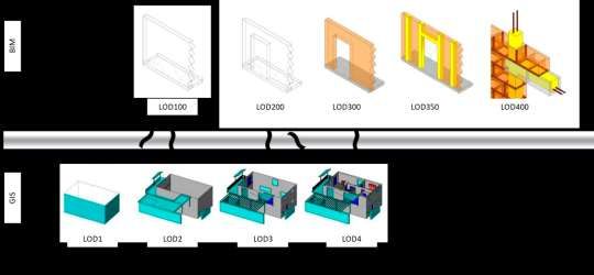
the “level of information detail,” where “level of model detail” is defined as the description of
   graphical content of models, and “level of information detail” is defined as the description of
   non-graphical content of models. The UK levels (both the level of model detail and the level
   of model information) progresses from level 1 to 7. ISO also uses a collective term “Level of
   Information Need (LOIN),” which includes geometrical and non-geometrical data. LOIN is
   defined as a “framework which defines the extent and granularity of information” in ISO/TC
   59/SC 13 (2018).

   The definitions of LOD vary from different countries and regions, but given that the definition
   introduced by Vico Software in 2004 evolved in North America and its levels were based on a
   3-digit number, and the definition introduced by the bips evolved in Europe and its levels
   were based on a 1-digit number, one can intuitively surmise that, in many cases, when LOD is
   defined with a 3-digit number (e.g. LOD100, LOD200), the definitions are influenced by
   those from North America; and when it is defined with a 1-digit number (e.g. level 1, level 2),
   the definitions are influenced by those from Europe. Also, different terms are used to make
   distinctions between LOD graphic and LOD information. For instance, in PAS 1192-2, the
   terms “level of model detail” and “level of information detail” are used to make the
   distinction, and in BIMForum’s LOD Specification, the terms “Element Geometry” and
   “Associated Attribute Information” are used to make the distinction. Regardless of the
   difference in terms, the geometry and non-geometric information are treated equally
   important in many standards or specifications.

   In Hong Kong, CIC (2019) defines Level of Development with a progression from LOD100
   to LOD500. Similarly, the Drainage Services Department (DSD) (2019) follows these levels
   with an exception of LOD500—the DSD manual does not define LOD500. The definitions in
   the form of 3-digit levels are similar to the ones developed in North America, and the 2019
   version of CIC’s “BIM Standards – General” notes that its LOD definitions “follow the LOD
   definitions developed by the American Institute of Architects (AIA).” The AIA document
   here refers to the AIA’s BIM protocol document (AIA 2013), Building Information Modeling
   Protocol Form. As for the distinction between LOD graphic and LOD information, DSD
   (2019) defines them separately with the terms LOD-G and LOD-I. CIC (2019) does not
   distinguish LOD-G and LOD-I, but CIC’s “BIM Standards for Mechanical, Electrical and
   Plumbing (MEP)” and “BIM Standards for Underground Utilities (UU)” do define LOD-G
   and LOD-I separately.

       2.3 Comparison of BIM LOD and CityGML LOD
   Apart from the LODs defined in the BIM sector, the level of detail defined in the open GIS
   standard CityGML(CityGML LOD) is the widely used and accepted level of detail in the GIS
   sector. It is also worth noting that open BIM standard IFC does not define LOD, and it is
   rather specifications, guidelines, or BIM execution plans in the BIM sector that defines LOD.
   CityGML is standardized by Open Geospatial Consortium (OGC) and a schema for
   interoperability and structuring urban data. CityGML is built on top of GML, and GML only
   describes the geometry—CityGML adds semantics within the urban context.

Development of the BIM Data Repository of Lands Department (11202)
Nelson Yam (Hong Kong SAR, China), Calvin Kam and Min Song (USA)
FIG e-Working Week 2021
Smart Surveyors for Land and Water Management - Challenges in a New Reality
Virtual, 21–25 June 2021
The CityGML LOD is defined in five levels (OGC 2006), progressing from LOD0 thru
LOD4. LOD0 can be considered as a 2 ½D digital terrain model, without blocks of buildings.
LOD1 is capable of modelling a mass model of a building with flat roofs, and LOD2 is
capable of modelling pitched roofs and thematically differentiated surfaces. BIM LOD100 is
similar to CityGML LOD1 and LOD2. CityGML LOD 3 is capable of modelling detailed
walls, roofs, balconies, trees, and transportation objects, and mapping surfaces with texture.
BIM LOD200 is comparable to CityGML LOD3. CityGML LOD4 is capable of modelling
interior objects, such as interior walls, rooms, and furniture. The overall geometric
comparison of BIM LOD and CityGML LOD is shown in Figure 1—but the figure shows a
rough comparison as one level cannot be squarely mapped with one level in the other domain.
In general, the accuracy, granularity, and completeness of CityGML LOD are lower than
those of BIM LOD. Because of this simplicity, CityGML is more operable and usable on a
city level. A 3D model of a city, however, often originates from an authoring tool—often a
BIM authoring tool—so a transition needs to take place in BIM DR, converting a BIM to an
open BIM (IFC), and ultimately to an open GIS (CityGML). The Civil Engineering and
Development Department (CEDD)’s is performing a BIM harmonization amongst a few of its
strategy project and preparing a BIM Harmonization Guidelines following the above
transition path. The above transition roadmap does not mean that IFC models and CityGML
models cannot coexist. IFC models and CityGML models can be shown through the same
web interface, bringing in the benefits of minimizing the data loss during the conversion from
IFC to CityGML. This has been showcased through the prototype developed for BIM DR.
Figure 1. A broad comparison of BIMForum’s level of development specification and OGC’s
CityGML level of detail specification.
2.4 Minimum LODs over the lifecycle of a project
While we adopted LOD definitions in CIC (2019), we notice a notable difference between
CIC BIM Standards and AIA (2008) that the CIC document differentiates LOD-G and LOD-I,
Development of the BIM Data Repository of Lands Department (11202)
Nelson Yam (Hong Kong SAR, China), Calvin Kam and Min Song (USA)
FIG e-Working Week 2021
Smart Surveyors for Land and Water Management - Challenges in a New Reality
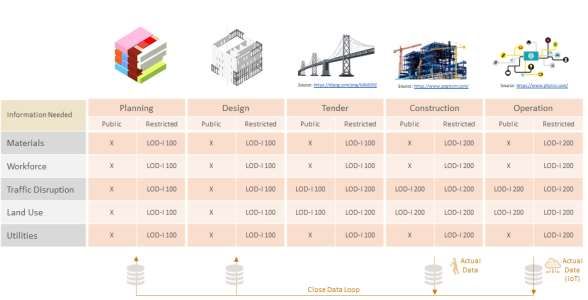
Virtual, 21–25 June 2021while the AIA document does not explicitly differentiate those, but the definitions in both documents progresses from LOD100 to LOD500. The entries in Figure 2 are our initial assessments on the minimum LOD-Is required for different stages in a project life cycle. Even with a low level of development, decision support information can be formulated. For instance, during the Planning and Design phases, LOD-I 100 (e.g. GFA or volume of a building) can parametrically provide a ballpark estimate of the “general” workers’ workhours needed (decision-support information). And the general workers work hours used during the Planning and Design stages can be validated and refined against the actual workhours collected during the Construction phase. The validated and refined metric can be used for future Planning and Design stages. AIA (2008) notes 3D object (referred to as Model Elements in AIA (2008)) at LOD100 may be used for analyses that are based on volume, area and orientation, such as developing cost estimate based on current area and volume; and they may also be used for project phasing and determination of overall project duration. Hence, meaningful information, such as volume and area, can be derived from 3D objects at LOD100 alone and such information can be useful for a large-scale analysis on a city level, e.g. analysis for urban planning. Figure 2. Minimum LOD-Is for each project stage. The entries in Figure 3 are our initial assessments on the minimum LOD-Gs and we observed that a higher LOD-Gs is usually used in practice. To keep the models simple and shareable, the definitive models generated during the Construction Stage may have to be reverse engineered or simplified to a lower LOD-G as the models generated during the Planning Stage may no longer be accurate or valid. Development of the BIM Data Repository of Lands Department (11202) Nelson Yam (Hong Kong SAR, China), Calvin Kam and Min Song (USA) FIG e-Working Week 2021 Smart Surveyors for Land and Water Management - Challenges in a New Reality Virtual, 21–25 June 2021
Figure 3. Minimum LOD-Gs for each project stage.

   CIC has completed a study in 2021 on the 3D and BIM Data Use Case Requirements of the
   Construction Industry for the Development of Digital Hong Kong. The project distilled and
   consolidated 10 potential use cases of BIM/GIS integration from 47 use cases. We try to
   stock take the proposed minimum LODs required for the 10 use cases to see the possible
   demand for different LODs in the BIM DR below.

   ▪ Use case #1. Underground Utilities Study and Space Management
     The main purpose of this use case is clash analysis and this requires accurate positioning of
     3D objects. The study concluded that the models should have a 5cm (0.05m) survey
     accuracy. Accordingly, the minimum LOD for this purpose can be LOD300.

   ▪ Use case #2. Visualisation of Construction Project Lifecycle
     This use case mainly revolves around creating a 4D model to help manage the key
     information of project lifecycle. On a zonal and city context, LOD100 delivers generic
     representation and can derive information such as cost per square foot. The minimum LOD
     for this purpose can be LOD100 or 200.

   ▪ Use case #3. Geotechnical Study
     This use case is mainly to assess potential landslide risks. With LOD200, the approximate
     size and shape of the foundation object can be provided. The basic information required for
     a borehole could be simple hole ID, depth, coordinates, and elevation. The minimum LOD
     for this purpose can be LOD200.

   ▪ Use case #4. Traffic Impact Assessment (TIA)
     This use case leverages Swept Path Analysis to simulate modular integrated construction
     (MiC) trucks passing through highways as well as narrow streets in dense urban areas. 3D
     objects of roads can be in approximate size without the details of pavement layers, road
     signs, and texture. The minimum LOD for this purpose can be LOD200.

Development of the BIM Data Repository of Lands Department (11202)
Nelson Yam (Hong Kong SAR, China), Calvin Kam and Min Song (USA)
FIG e-Working Week 2021
Smart Surveyors for Land and Water Management - Challenges in a New Reality
Virtual, 21–25 June 2021
▪ Use case #5. Foundation Design
This use case is to design foundation structures in an automatic way by using the data from
geological investigation. The purpose of the automatic design to generate varying scenarios
and study the feasibility. Similar to the “Geotechnical Study” above, the minimum LOD for
this purpose can be LOD200.
▪ Use case #6. Excavation Permit (XP) Application
This use case is to prevent accidental damages to the existing underground utilities by
informing the existing underground utilities during the excavation permit procedure. Similar
to the “Underground Utilities Study and Space Management” above, the minimum LOD for
this purpose can be LOD300.
▪ Use case #7. Environmental Impact Assessment (EIA)
Examples of EIA includes air quality impact assessment, water quality assessment, noise
impact assessment and landscape & visual impact assessment, etc. Even a simple mass
model can provide meaningful results. The minimum LOD for this purpose can be LOD100.
▪ Use case #8. Building Energy Monitoring and Facility Management
This use case is to encourage building owners to share the performance (energy, water, and
equipment) data of their buildings, so the industry, academy, and government can benefit as
a whole from the shared data. Approximate size and shape of selected MEP objects can
address this. The minimum LOD for this purpose can be LOD200.
▪ Use case #9. Air Ventilation Assessment
This use case is to simulate the effect of regional air ventilation by visualizing the air flow
or wind speed in an area before and after proposing a development during the planning
stage. This study will be feasible with a rough geometry of buildings. The minimum LOD
for this purpose can be LOD100.
▪ Use case #10. Premium Assessment and Property Valuation
This use case is to estimate the market value of a property by comparing the property with
similar properties nearby. Providing photorealistic images and delivering the concept of
space are relatively important. Properties can look realistic with LOD100 or 200 even by
applying high resolution texture. Modelling space objects and linking the IDs of properties
or spaces with pre-existing databases of LandsD, Planning Department, and Buildings
Department could also provide rich information, but integrating the scatter data seems to be
the challenge. The minimum LOD for this purpose can be LOD200.
The study in this section focused on assessing the minimum LODs required to support the 10
use cases identified by CIC. For the use cases, the minimum LODs can be in the range of
LOD100 and 200 throughout the five stages defined in this section.
Development of the BIM Data Repository of Lands Department (11202)
Nelson Yam (Hong Kong SAR, China), Calvin Kam and Min Song (USA)
FIG e-Working Week 2021
Smart Surveyors for Land and Water Management - Challenges in a New Reality
Virtual, 21–25 June 20213. Technical options for simplifying BIM
On a large project, a BIM file can have more than 50,000 3D objects for a single discipline
when LOD is in the range of LOD300 to LOD350. If it is in the range of LOD350 and
LOD400, the number of 3D objects to be built or constructed in a month could reach up to
20,000. Uploading all these objects to BIM DR may be necessary to support all potential use
cases in the future. However, when a BIM DR use case is determined and requirements are
refined, certainly not all of these objects will be required. The BIM has to be simplified and
made shareable for the end-user when a use case is determined. This section introduces two
approaches to the simplification: exclusion and reverse engineering.
3.1 Exclusion
BIM can be simplified by excluding certain 3D objects (or objects with certain properties).
This can be done, for instance, by controlling the visibility or by creating a filter in a BIM
authoring tool side via a plugin to customize the filtering process, or at the BIM and GIS
integrated platform side. The filtered objects will vary depending on the use case. If the use
case, for instance, is a 4D model of a project, 3D objects such as drywall frames and pipe
hangers may be filtered out as they are unnecessarily granular. If the use case is a flooding
simulation, all objects may be excluded except for structural objects and openings. For MEP
lines, certain objects can be excluded as well for most use cases—objects such as hangers or
supports are unlikely to be used for most use cases on a city level. Determining the use cases
and identifying the necessary object types (or identifying unnecessary object types) based on a
certain use case will be helpful for creating a shareable and simplified BIM Data Repository.
3.1.1 Authoring tool
The approach is mentioned in the last paragraph. The advantage of this approach is that many
of these filtering functions are readily available in the BIM authoring tool (except for a
plugin). The disadvantage of this approach is that a filter is tool-specific and it may have to be
updated when new types of objects are modelled for a project.
3.1.2 Open BIM DR
The other approach is developing and applying a filter on the BIM DR side. The native BIM
file can be converted into a full IFC file and stored in BIM DR. From BIM DR, an IFC filter
can be applied to exclude unnecessary 3D objects based on IFC class names or property
names. The full IFC file and filtered IFC file can be both maintained. The advantage of this
approach is that the class names or property names of IFC are consistent regardless of the
BIM authoring tools used since the IFC files follow the IFC standard. The disadvantage of
this approach is that the success of filtering relies on the quality of the IFC files—if the IFC
exporter underperforms and most of the native object types are not converted to the right IFC
object types (or the native properties are not converted to the right IFC properties), the filter
will not operate as intended. Apart from this, filtering through visibility checks is also an
option. This approach checks the visibility of 3D objects from many different viewpoints and
assesses whether to filter out certain objects or not. For instance, one BIM DR use case may
only need exterior objects to be included and all the interior objects to be filtered out. E.g. the
use case of visualizing on a city scale and flying over a city would not require interior objects.
Development of the BIM Data Repository of Lands Department (11202)
Nelson Yam (Hong Kong SAR, China), Calvin Kam and Min Song (USA)
FIG e-Working Week 2021
Smart Surveyors for Land and Water Management - Challenges in a New Reality
Virtual, 21–25 June 2021In such a case, visibility checks can be done at multiple points outside the building and if a
certain object is assessed to be visible from outside, those objects can remain and other
objects can be excluded. The prototype we have adopted for open BIM DR has included this
functionality, which makes the prototype less computationally expensive and improving the
performance.
Figure 4. Simplifying BIM by using an algorithm excluding interior IFC objects.
3.2 Reverse engineering
Besides excluding unnecessary 3D objects, the geometric or the non-geometric information
can be reverse engineered to create a new and simplified version of the information. For the
geometric information, this can be done by either reducing the number of vertices and faces of
a mesh (mesh simplification) or by generating a new geometry based on the original
geometry. For the non-geometric information, computation, such as averaging, can be
applied.
3.2.1 Mesh simplification
The file size can be reduced through mesh simplification. For instance, a hollow profile object
with thousands of faces can be simplified to a simple solid profile object with less faces. This
usually can be done from a BIM authoring tool and some authoring tools have options for
choosing the granularity of 3D objects. The figure below shows an example of a mesh
simplification for pipe objects. The number of triangles has been reduced on the right side
after simplification.
Figure 5. Simplifying the mesh by reducing the number of vertices and triangles.
3.2.2 Object reconstruction
Simplification can be also done by generating a new geometry based on the original
geometry. A reference object can be selected from the original model and a new object can be
created based on the reference object. For instance, an LOD400 drywall would have objects
representing frame objects and gypsum objects. To simplify this, a new wall object can be
created, which encapsulates all the frame objects and gypsum objects wall. The figure below
shows another example of simplification through object reconstruction. In this example, only
the slab object, IfcSlab, from the IFC model is loaded to FME and used as a reference object
Development of the BIM Data Repository of Lands Department (11202)
Nelson Yam (Hong Kong SAR, China), Calvin Kam and Min Song (USA)
FIG e-Working Week 2021
Smart Surveyors for Land and Water Management - Challenges in a New Reality
Virtual, 21–25 June 2021for creating a new object. Through FME, a boundary is extracted from the IfcSlab object
(using BoundExtractor in FME) and a mesh object is created based on the boundary (using
MeshCreator_IFC in FME). The mesh object is extruded (using LODExtrusionBlock) to
create an appearance close to the CityGML building at LOD2, which is similar to BIM at
LOD100. After the extruded object is set with the correct coordinate system, a proper
CityGML object is created by providing the semantics of ground, roof and wall to the right
surfaces.
Figure 6. Reconstructing the geometry of the building by using a reference object (IfcSlab
object)—adapted from Jusuf, et al. (2017).
The study in this section focused on technical options for simplifying BIM. The two
approaches that we have studied are simplifying by exclusion or reverse engineering. The
LandsD's BIM DR project team is exploring the exclusion approach, which is a combination
of a plugin developed to exclude unnecessary objects and an algorithm to exclude interior
objects.
4. Technical options for open standards-based integration
With the background of CEDD and CIC studies, LandsD and other stakeholders in Hong
Kong is ready to adopt IFC for BIM and CityGML for GIS as open standard formats. This
also aligns with the typical practices around the world. When creating an “integrated” open
BIM and GIS platform, the open standards format(s) landing on the platform can be either
IFC or CityGML, or both. Accordingly, we can consider multiple options for the integration,
and the four options listed below are relatively more in need of attention than others.
Development of the BIM Data Repository of Lands Department (11202)
Nelson Yam (Hong Kong SAR, China), Calvin Kam and Min Song (USA)
FIG e-Working Week 2021
Smart Surveyors for Land and Water Management - Challenges in a New Reality
Virtual, 21–25 June 20214.1 Visualization Tool → CityGML
The final open BIM and GIS integrated platform is made up of CityGML models in this case.
The models shown in the GIS context are all CityGML models. A majority of the open
standards-based city models in operation today fall under this category, where the buildings
are first created in tools that focus more on the visualization and then converted to CityGML.
Examples of such tools focused more on visualization including SketchUp, RhinoCity, and
Bentley Map. One can model buildings with these tools, but they are not BIM tools in a strict
sense, because these visualization tools lack the definitions of building elements as they do
not have predefined classes for building elements, such as floors, walls, columns, windows,
and doors. They also lack parametric relationships between different classes of building
elements by which any changes to 3D objects are instantaneously reflected to the drawings
and the dimensions therein. The tools that are capable of defining different building
elements and establishing parametric relationships are BIM tools, e.g. Revit, Tekla, and
ArchiCAD, which are not visualization tools. (Note that the term “visualization tool” in this
section is used to address tools that focus more on the visualization of buildings, such as
SketchUp, RhinoCity, and Bentley Map.)The majority of the open standards-based city
models today use visualization tools for modelling buildings and converting them to a
CityGML format via its generic function or with plug-ins. For instance, SketchUp and
RhinoCity use plug-ins to export CityGML whereas Bentley Map use it generic function to
export CityGML.
This method of using a visualization tool and exporting to a CityGML format tends to work
well, because the buildings created by visualization tools are mainly represented by boundary
representation (brep), which aligns with the method used in CityGML, and because the
buildings created by visualization tools do not have the complex classification of building
elements. This method has been proven in the industry and is the underlying method of most
of the open standards-based city models that we see today. But the limitation is that this
option is not tapping into the rich semantics available in BIM. Also, the LOD of the city
models tends to remain on the levels of CityGML LOD1, LOD2, or LOD3, and interior
objects (LOD4) are often left out.
4.2 IFC → CityGML
As it is with the previous method, the final open BIM and GIS integrated platform is made up
of CityGML models in this case. But the intention here is to create CityGML models by
converting IFC models originating from BIM authoring tools (and not from visualization
tools). In the last 10 years, research on converting an IFC model to a CityGML model has
been active. Van Berlo and de Laat (2011) and El-Mekawy, et al. (2012) studied the
conversion from IFC to CityGML, Donkers (2013) and Xun, et al. (2014) studied the mapping
of IFC semantics to CityGML semantics, Yu and Teo (2014) studied the conversion from IFC
to CityGML through geometric division and geometric information editing, and Deng, et al
(2016) studied mapping rules between IFC and CityGML using an instance-based method and
designed a reference ontology. FME is also used in a wide range of research for converting
IFC to CityGML(e.g. Jusuf, et al (2017)).
Development of the BIM Data Repository of Lands Department (11202)
Nelson Yam (Hong Kong SAR, China), Calvin Kam and Min Song (USA)
FIG e-Working Week 2021
Smart Surveyors for Land and Water Management - Challenges in a New Reality
Virtual, 21–25 June 2021A certain gap, however, exists between the research and practice, especially when the open
standards-based BIM DR for LandsD should be scalable to multiple types of scenarios. In
practice, the quality of IFC models varies greatly, and the IFC models from real life project
are often complex buildings elements. IFC models used in the research, on the other hand,
tend to be of small scope, often excluding unpredictable and complex factors. A case that has
successfully converted a large number of IFC models—originating from different project
teams—to CityGML models on a city level is hard to find, if not absent at this moment. The
concern is that while few sample conversions may work with conversion engines designed or
customized for the samples, creating a generic conversion engine that successfully converts
many variations of IFC models to CityGML models is still challenging. The first step of
resolving this issue would be improving the quality and minimizing the variations of IFC
models by establishing IFC-related specifications, guiding the model authors to follow the
specifications, and implementing Information Delivery Specification (IDS) checker for
automatically validating against the specifications.
4.3 CityGML → IFC
The final open BIM and GIS integrated platform is made up of IFC models in this case. This
option is less convincing than the previous IFC → CityGML option for the following reasons:
(1) the size of IFC models is typically larger than that of CityGML models as IFC tend to
contain more information, (2) there is little merit in converting a less complicated schema to a
more complicated schema for a city model, and (3) the process of the complication through
the conversion does not enrich IFC information.
For instance, many of the entity and property types that make IFC useful are absent in
CityGML. IFC information such as IfcElementQuantity, LoadBearing, and IfcClassification,
among many others, will be empty when a CityGML model is converted to an IFC model
because they are originally not defined in CityGML. Also, when the geometry of CityGML is
converted to that of IFC, the IFC model will not have accurate information on how the
geometry is generated because CityGML only uses boundary representation (brep) but IFC
also uses the parametric modelling techniques of constructive solid geometry (CSG) and
swept solid. All the objects in the IFC model originating from a CityGML model will be
represented by brep only. The fact that there has been less research on CityGML to IFC
conversion—compared to the research on IFC to CityGML conversion—also shows that the
research and the industry demand for CityGML to IFC conversion is not as strong as the
demand for the other, such as IFC to CityGML.
One of the use cases that may benefit from the CityGML to IFC conversion is when the BIM
community or the designers of individual projects need to download the models of
neighbouring areas from a CityGML-based BIM DR to understand their project in the context
of the city during the designing process. However, the less-smart IFC model from the
CityGML to IFC conversion will naturally give way to other more effective ways to handle
that case by, for instance, converting CityGML models to DWG or DXF formats that can
preserve the geometry and is easier than converting CityGML models to IFC models. Since
many BIM authoring tools can also import these formats (that only focuses on geometry), the
Development of the BIM Data Repository of Lands Department (11202)
Nelson Yam (Hong Kong SAR, China), Calvin Kam and Min Song (USA)
FIG e-Working Week 2021
Smart Surveyors for Land and Water Management - Challenges in a New Reality
Virtual, 21–25 June 2021BIM community or the designers can also use these formats for understanding the geometric
context of their projects.
4.4 IFC + CityGML
The final open BIM and GIS integrated platform is made up of both CityGML and IFC
models. This is a hybrid approach where the databases of CityGML and IFC are maintained
and the models of CityGML and IFC are visualized through a single viewer. This approach is
the one that was adopted for the open BIM DR prototype. The prototype shows IFC models in
a CityGML viewer by converting the geometry of the IFC models to a glTF format. This is
done to improve the performance of the prototype. The original IFC model is also available
on a dedicated viewer should a user want to see the details of the IFC model. Querying
against multiple IFC models and CityGML models is also possible.
The study in this section focused on technical options for open standards-based integration.
The current BIM DR prototype has taken the approach of making both the IFC and CityGML
models available from a single viewer. In parallel, the LandsD's BIM DR project team is also
evaluating the feasibility of converting IFC models to CityGML models.
5. Conclusion
We have identified the minimum LODs required for each of five project stages defined in this
paper. The minimum LODs are in the range of LOD100 and 200. We see that objects at
LOD100-200 can generate information such as volume, area, orientation, and rough
geometry, and based on this information, ballpark estimates can be derived for many of the
use cases desired by the stakeholders on a city level.
Regarding the issues on simplifying BIM, we have reviewed different approaches in
simplifying BIM. LandsD’s BIM DR project team is exploring the use of customized filter
that can be installed as a plugin (called Extractor as developed by AECOM in CEDD’s BIM
harmonisation project) on a BIM authoring tool. This can be used to filter out or exclude
unnecessary objects to help simplification. The team will continue to explore the use of an
algorithm to exclude interior objects from an IFC model, as illustrated in Figure 4, which is
currently used in the BIM DR prototype.
To support open standards and interoperability, we have reviewed different data standards in
the paper. Currently, the BIM DR prototype was developed to operate with the “IFC +
CityGML” option explained in the paper where IFC and CityGML models are both available
from a single viewer. LandsD will exploring the “IFC to CityGML” option explained in the
paper in the development of the full scale BIM DR.
Development of the BIM Data Repository of Lands Department (11202)
Nelson Yam (Hong Kong SAR, China), Calvin Kam and Min Song (USA)
FIG e-Working Week 2021
Smart Surveyors for Land and Water Management - Challenges in a New Reality
Virtual, 21–25 June 2021REFERENCES
AIA. 2008. “AIA document E202-2008: Building information modeling protocol exhibit”.
American Institute of Architects (AIA), Washington, DC.
AIA. 2013. “AIA document G202-2013: Project building information modeling protocol
form.”. American Institute of Architects (AIA), Washington, DC.
BIMForum. 2013. “Level of development specification.” BIMForum,
(Feb. 26, 2021).
Byggeri Informationsteknologi Produktivitet Samarbejde (bips). 2007. 3D Working Method
2006. Digital Construction. Denmark.
British Standards Institution (BSI). 2013. “PAS 1192-2 Specification for information
management for the capital/delivery phase of construction projects using building
information modelling”.
Construction Industry Council (CIC). 2019. CIC BIM Standards—General.
Deng, Y., Cheng, J.C.P., and Anumba, C. 2016. Mapping between BIM and 3D GIS in
different level of details using schema mediation and instance comparison. Autom.
Constr. 2016, 37, 1–21.
Development Bureau (DEVB). 2020. “Development Bureau Technical Circular (Works) No.
12/2020”.
Donkers, S. 2013. Automatic Generation of CityGML LoD3 Building Models from IFC
Models. Master’s Thesis, Department of GIS Technology, TU Delft, Delft, The
Netherlands.
Drainage Services Department (DSD). 2019. BIM Modelling Manual.
El-Mekawy, M., Östman, A., and Hijazi, I. 2012. A Unified Building Model for 3D Urban
GIS. ISPRS Int. J. Geo-Inf. 2012, 1, 120–145.
ISO/TC 59/SC 13. 2018. “ISO 19650-1:2018 Organization and digitization of information
about buildings and civil engineering works, including building information modelling
(BIM) — Information management using building information modelling — Part 1:
Concepts and principles”.
Jusuf, S. K., Mousseau, B., Godfroid, G., and Hui V. S. J. 2017. Integrated modeling of
CityGML and IFC for city/neighborhood development for urban microclimates analysis.
CISBAT 2017 International Conference.
Open Geospatial Consortium (OGC). 2006. “Candidate OpenGIS CityGML Implementation
Specification”.
Van Berlo, L. and de Laat, R. 2010. Integration of BIM and GIS: The development of the
CityGML GeoBIM extension. In Proceedings of the 5th International 3D GeoInfo
Conference, Berlin, Germany, 3–4 November 2010.
Xun, X., Lieyun, D., and Hanbin, L., Ling, M. 2014. From building information modeling to
city information modeling. J. Inf. Technol. Constr. 2014, 19, 292–307.
Yu, S.-C. and Teo, T.-A. 2014. The Generalization of BIM/IFC Model for Multi-Scale 3D
GIS/CityGML Models.
Development of the BIM Data Repository of Lands Department (11202)
Nelson Yam (Hong Kong SAR, China), Calvin Kam and Min Song (USA)
FIG e-Working Week 2021
Smart Surveyors for Land and Water Management - Challenges in a New Reality
Virtual, 21–25 June 2021BIOGRAPHICAL NOTES Mr. Nelson YAM is a professional member of Hong Kong Institute of Surveyors for 23 years. He is the section head of Building Information Modelling of Lands Department. He had a wide range of solid experience on working with spatial data throughout government projects including territory-wide remote sensing projects, departmental GIS development, territory- wide 3D Spatial Data development, heritage laser scanning projects for rebuilding of housing estates, departmental tree database development, BIM and GIS data integration for housing development projects, integration of BIM data into 3D GIS environment and common standards for works departments. Currently, he is actively participated in delivering the BIM standards in Hong Kong through the committee work of various organisations including BIM Horizontal Harmonization for BIM / GIS Integration under the First Phase of Kwu Tung North and Fanling North New Development Area; design and the implementation of territory wide BIM Data Repository of Lands Department; and Implementation of e-Building Plan Data Processing System by integrating with Electronic Submission Hub of Building Department. Dr. Calvin Kam is the Founder and CEO of Strategic Building Innovation and bimSCORE (SBI.bimSCORE). He is also an Adjunct Professor at Stanford University’s Center for Integrated Facility Engineering (CIFE), where he specializes in strategic innovation such as Management Scorecards, Building Information Modelling (BIM), Virtual Design and Construction (VDC) and Sustainable Developments. He has given many of keynote and plenary speeches, published a number of book chapters, APEC official publications, journal articles, and conference papers. He was a recipient of various AIA, ASCE, SOM, Stanford University Fellowships as well as Engineering News Record’s "20 under 40" awards, and the inaugural Junior Alumni Award from USC Department of Civil & Environmental Engineering among other honours and awards. He is a registered Architect in the State of California, a Professional Engineer in the District of Columbia, and a LEED Accredited Professional. Dr. Min Song is a senior associate at Strategic Building Innovation and bimSCORE (SBI.bimSCORE). He has worked on high-rise building, oil and gas, airport, and commercial building projects around the world - in Korea, USA, UAE, Kuwait, Germany, Sweden, and Peru. While working in the industry for 15 years, he also pursued a PhD degree at Stanford University in the area of Construction Engineering and Management. He is a Project Management Professional and a LEED Accredited Professional and has published a number of scholarly journal articles, working papers, and technical reports during his time at Stanford University’s Center for Integrated Facility Engineering (CIFE). CONTACTS Mr. Nelson YAM Lands Department Building Information Modelling Section, Survey and Mapping Office, Lands Department Development of the BIM Data Repository of Lands Department (11202) Nelson Yam (Hong Kong SAR, China), Calvin Kam and Min Song (USA) FIG e-Working Week 2021 Smart Surveyors for Land and Water Management - Challenges in a New Reality Virtual, 21–25 June 2021
23/F, 333 Java Road, North Point
   Hong Kong
   Tel. +852 2231 3840
   Email: slsbim@landsd.gov.hk
   Web site: www.landsd.gov.hk

   Dr. Calvin KAM
   Strategic Building Innovation • bimSCORE
   4288 Dublin Blvd., Suite 218
   Dublin, CA 94568
   USA
   Tel. +1-650-888-1916
   Email: calvin.kam@sbi.international
   Web site: www.sbi.international

   Dr. Min SONG
   Strategic Building Innovation • bimSCORE
   4288 Dublin Blvd., Suite 218
   Dublin, CA 94568
   USA
   Tel. +1-650-804-5924
   Email: min.song@sbi.international
   Web site: www.sbi.international

Development of the BIM Data Repository of Lands Department (11202)
Nelson Yam (Hong Kong SAR, China), Calvin Kam and Min Song (USA)
FIG e-Working Week 2021
Smart Surveyors for Land and Water Management - Challenges in a New Reality
Virtual, 21–25 June 2021
You can also read