DNA PPCx PowerDNA Cube User Manual - January 2021 PN Man-PPCx-1212 Copyright 1998-2021 United Electronic Industries, Inc. All rights reserved ...
←
→
Page content transcription
If your browser does not render page correctly, please read the page content below
DNA PPCx PowerDNA Cube
                       User Manual

                            January 2021
                            PN Man-PPCx-1212

© Copyright 1998-2021 United Electronic Industries, Inc. All rights reserved.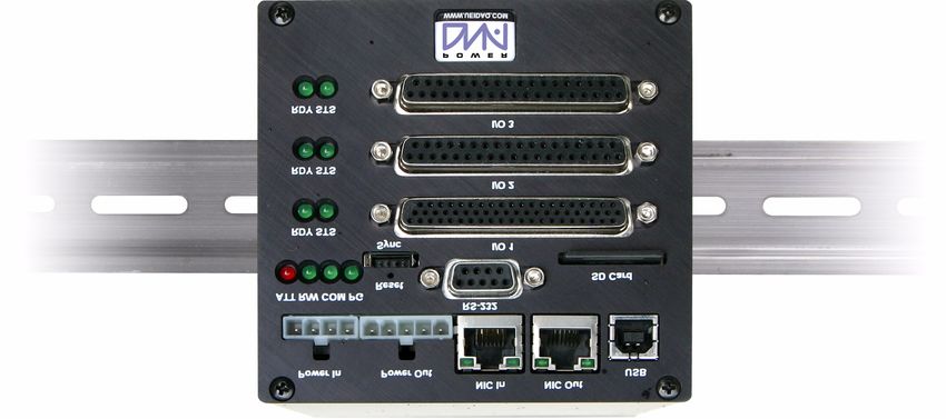
No part of this publication may be reproduced, stored in a retrieval system, or transmitted, in any form
   by any means, electronic, mechanical, by photocopying, recording, or otherwise without prior written
   permission.
   Information furnished in this manual is believed to be accurate and reliable. However, no responsibility
   is assumed for its use, or for any infringement of patents or other rights of third parties that may result
   from its use. All product names listed are trademarks or trade names of their respective companies.

   See the UEI website for complete terms and conditions of sale:
   http://www.ueidaq.com/cms/terms-and-conditions

   Note: CE Mark EMC compliance is based on the DNA-PPC8 being used in conjunction
   with the DNA-PSU-series AC/DC power brick that is included with each Cube.

Contacting United Electronic Industries
   Mailing Address:
   27 Renmar Avenue
   Walpole, MA 02081
   U.S.A.

   For a list of our distributors and partners in the US and around the world, please contact a member of our
   support team:

   Support:
   Telephone:         (508) 921-4600
   Fax:               (508) 668-2350
   Also see the FAQs and online “Live Help” feature on our web site.

   Internet Support:
   Support:          support@ueidaq.com
   Website:          www.ueidaq.com
   FTP Site:         ftp://ftp.ueidaq.com

Product Disclaimer:
                                                    WARNING!
   DO NOT USE PRODUCTS SOLD BY UNITED ELECTRONIC INDUSTRIES, INC. AS CRITICAL
   COMPONENTS IN LIFE SUPPORT DEVICES OR SYSTEMS.
   Products sold by United Electronic Industries, Inc. are not authorized for use as critical components in
   life support devices or systems. A critical component is any component of a life support device or
   system whose failure to perform can be reasonably expected to cause the failure of the life support
   device or system, or to affect its safety or effectiveness. Any attempt to purchase any United Electronic
   Industries, Inc. product for that purpose is null and void and United Electronic Industries Inc. accepts
   no liability whatsoever in contract, tort, or otherwise whether or not resulting from our or our
   employees' negligence or failure to detect an improper purchase.
   Specifications in this document are subject to change without notice. Check with UEI for
   current status.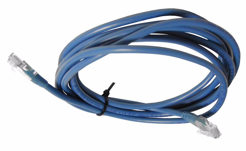
DNA-PPCx PowerDNA Cube                      i
                                                                                                                        Table of Contents

                                                   Table of Contents
        Chapter 1 Introduction . . . . . . . . . . . . . . . . . . . . . . . . . . . . . . . . . . . . . . . . . . . . . . . . . . . . . 1
        1.1             PowerDNA Overview . . . . . . . . . . . . . . . . . . . . . . . . . . . . . . . . . . . . . . . . . . . . . . . . . . 2
        1.1.1                What’s in the Package . . . . . . . . . . . . . . . . . . . . . . . . . . . . . . . . . . . . . . . . . . . 3
        1.2             Overview . . . . . . . . . . . . . . . . . . . . . . . . . . . . . . . . . . . . . . . . . . . . . . . . . . . . . . . . . . . 3
        1.3             Specifications . . . . . . . . . . . . . . . . . . . . . . . . . . . . . . . . . . . . . . . . . . . . . . . . . . . . . . . 6
        1.4             DC Power Thresholds . . . . . . . . . . . . . . . . . . . . . . . . . . . . . . . . . . . . . . . . . . . . . . . . . 7
        Chapter 2 Installation and Configuration . . . . . . . . . . . . . . . . . . . . . . . . . . . . . . . . . . . . . . 8
        2.1             Initial Installation - Overview . . . . . . . . . . . . . . . . . . . . . . . . . . . . . . . . . . . . . . . . . . . . 8
        2.2              Initial Installation – Start-to-finish Guide . . . . . . . . . . . . . . . . . . . . . . . . . . . . . . . . . . . 9
        2.2.1                     Inspect the package . . . . . . . . . . . . . . . . . . . . . . . . . . . . . . . . . . . . . . . . . . . . . 9
        2.2.2                     Install Software . . . . . . . . . . . . . . . . . . . . . . . . . . . . . . . . . . . . . . . . . . . . . . . . . 9
        2.2.3                     Initial Boot-up . . . . . . . . . . . . . . . . . . . . . . . . . . . . . . . . . . . . . . . . . . . . . . . . . 11
        2.2.4                     IP Addresses on the PowerDNA Cube . . . . . . . . . . . . . . . . . . . . . . . . . . . . . . 12
        2.2.5                     Improving Network Performance . . . . . . . . . . . . . . . . . . . . . . . . . . . . . . . . . . 13
        2.2.6                     PowerDNA Explorer Quick-Start. . . . . . . . . . . . . . . . . . . . . . . . . . . . . . . . . . . 17
        2.2.7                     Updating Firmware . . . . . . . . . . . . . . . . . . . . . . . . . . . . . . . . . . . . . . . . . . . . . 19
        2.2.8                     Firmware Update Instructions. . . . . . . . . . . . . . . . . . . . . . . . . . . . . . . . . . . . . 20
        2.3             Mounting and field connections . . . . . . . . . . . . . . . . . . . . . . . . . . . . . . . . . . . . . . . . . 22
        2.4             Wiring . . . . . . . . . . . . . . . . . . . . . . . . . . . . . . . . . . . . . . . . . . . . . . . . . . . . . . . . . . . . 23
        2.5             Peripheral Terminal Panel Wiring . . . . . . . . . . . . . . . . . . . . . . . . . . . . . . . . . . . . . . . 25
        Chapter 3 PowerDNA Explorer . . . . . . . . . . . . . . . . . . . . . . . . . . . . . . . . . . . . . . . . . . . . . 26
        3.1             The Main Window . . . . . . . . . . . . . . . . . . . . . . . . . . . . . . . . . . . . . . . . . . . . . . . . . . . 26
        3.2             Menu Bar . . . . . . . . . . . . . . . . . . . . . . . . . . . . . . . . . . . . . . . . . . . . . . . . . . . . . . . . . . 26
        3.2.1                File Menu . . . . . . . . . . . . . . . . . . . . . . . . . . . . . . . . . . . . . . . . . . . . . . . . . . . . 26
        3.2.2                Network Menu. . . . . . . . . . . . . . . . . . . . . . . . . . . . . . . . . . . . . . . . . . . . . . . . . 26
        3.2.3                View Menu . . . . . . . . . . . . . . . . . . . . . . . . . . . . . . . . . . . . . . . . . . . . . . . . . . . 29
        3.2.4                Help Menu . . . . . . . . . . . . . . . . . . . . . . . . . . . . . . . . . . . . . . . . . . . . . . . . . . . 30
        3.2.5                Toolbar . . . . . . . . . . . . . . . . . . . . . . . . . . . . . . . . . . . . . . . . . . . . . . . . . . . . . . 30
        3.2.6                Device Tree . . . . . . . . . . . . . . . . . . . . . . . . . . . . . . . . . . . . . . . . . . . . . . . . . . 30
        3.2.7                Settings Panel. . . . . . . . . . . . . . . . . . . . . . . . . . . . . . . . . . . . . . . . . . . . . . . . . 30
        3.2.8                Digital Input/Output Layer Settings . . . . . . . . . . . . . . . . . . . . . . . . . . . . . . . . . 33
        3.3             Analog Output Layer Settings . . . . . . . . . . . . . . . . . . . . . . . . . . . . . . . . . . . . . . . . . . 39
        3.4             Analog Input Layer Settings . . . . . . . . . . . . . . . . . . . . . . . . . . . . . . . . . . . . . . . . . . . 40
        3.5             Counter/Timer Layer Settings . . . . . . . . . . . . . . . . . . . . . . . . . . . . . . . . . . . . . . . . . . 41
        Chapter 4 The PowerDNA Core Module . . . . . . . . . . . . . . . . . . . . . . . . . . . . . . . . . . . . . . 44
        4.1             Device Architecture of DNA-CM . . . . . . . . . . . . . . . . . . . . . . . . . . . . . . . . . . . . . . . . 45
        4.1.1                 Device Architecture of DNA-PPC . . . . . . . . . . . . . . . . . . . . . . . . . . . . . . . . . . 46
        Chapter 5 Programming Layer-specific Functions . . . . . . . . . . . . . . . . . . . . . . . . . . . . . 47
        5.1             Overview . . . . . . . . . . . . . . . . . . . . . . . . . . . . . . . . . . . . . . . . . . . . . . . . . . . . . . . . . . 47
        5.2             Memory Map . . . . . . . . . . . . . . . . . . . . . . . . . . . . . . . . . . . . . . . . . . . . . . . . . . . . . . . 47

© Copyright 2021                         January 2021                                                                                        www.ueidaq.com
  United Electronic Industries, Inc.
                                                                                                                                               508.921.4600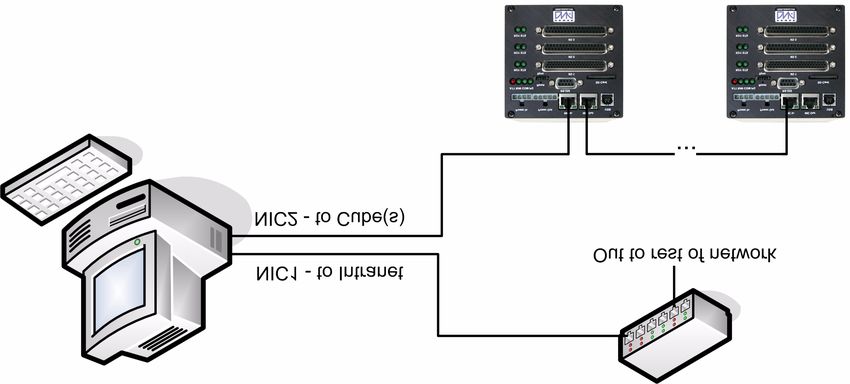
DNA-PPCx PowerDNA Cube                   ii
                                                                                                                        Table of Contents

        5.2.1                          Startup sequence (DNA-CM-5/8) . . . . . . . . . . . . . . . . . . . . . . . . . . . . . . . . . . 48
        5.2.2                          Startup Sequence (DNA-PPC-5/8) . . . . . . . . . . . . . . . . . . . . . . . . . . . . . . . . . 49
        5.2.3                          Interfacing to the CM Module Using a Serial Interface . . . . . . . . . . . . . . . . . . 49
        5.2.4                          Setting Parameters . . . . . . . . . . . . . . . . . . . . . . . . . . . . . . . . . . . . . . . . . . . . . 52
        5.3             How to Update Firmware . . . . . . . . . . . . . . . . . . . . . . . . . . . . . . . . . . . . . . . . . . . . . . 54
        5.3.1                 Clock and Watchdog Access . . . . . . . . . . . . . . . . . . . . . . . . . . . . . . . . . . . . . 54
        5.4             Common Layer Interface . . . . . . . . . . . . . . . . . . . . . . . . . . . . . . . . . . . . . . . . . . . . . . 54
        5.4.1               Channel List . . . . . . . . . . . . . . . . . . . . . . . . . . . . . . . . . . . . . . . . . . . . . . . . . . 54
        5.4.2               Configuration Flags. . . . . . . . . . . . . . . . . . . . . . . . . . . . . . . . . . . . . . . . . . . . . 56
        5.4.3               EEPROM User Area Access . . . . . . . . . . . . . . . . . . . . . . . . . . . . . . . . . . . . . 57
        5.4.4               PowerDNA Layer Signaling . . . . . . . . . . . . . . . . . . . . . . . . . . . . . . . . . . . . . . 59
        5.5             Register Map and Description . . . . . . . . . . . . . . . . . . . . . . . . . . . . . . . . . . . . . . . . . . 61
        5.6             Register Descriptions . . . . . . . . . . . . . . . . . . . . . . . . . . . . . . . . . . . . . . . . . . . . . . . . 62
        5.6.1                  Valid EM/CM Combinations for Non-Buffered Modes . . . . . . . . . . . . . . . . . . 67
        5.6.2                 FIFO Access . . . . . . . . . . . . . . . . . . . . . . . . . . . . . . . . . . . . . . . . . . . . . . . . . . 69
        5.6.3                 Command Mode . . . . . . . . . . . . . . . . . . . . . . . . . . . . . . . . . . . . . . . . . . . . . . . 70
        Appendix A . . . . . . . . . . . . . . . . . . . . . . . . . . . . . . . . . . . . . . . . . . . . . . . . . . . . . . . . . . . . . . 71
        A.1    Configuring a Second Ethernet Card Under Windows XP . . . . . . . . . . . . . . . . . . . . . 71
        A.2    Configuring a Second Ethernet Card Under Windows 2000 . . . . . . . . . . . . . . . . . . . 74
        A.3    Configuring a Second Ethernet Card Under Windows NT . . . . . . . . . . . . . . . . . . . . . 77
        A.4    Configuring a Second Ethernet Card Under Windows 95/98/SE/ME . . . . . . . . . . . . 79

© Copyright 2021                             January 2021                                                                                  www.ueidaq.com
  United Electronic Industries, Inc.
                                                                                                                                             508.921.4600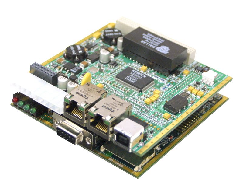
DNA-PPCx PowerDNA Cube                    iii
                                                                                                                  List of Figures

                                                              List of Figures
        Chapter 1 Introduction . . . . . . . . . . . . . . . . . . . . . . . . . . . . . . . . . . . . . . . . . . . . . . . . . . . . . 1
        1-1     DNA-PPCx Cube Specifications ...................................................................................6
        Chapter 2 Installation and Configuration . . . . . . . . . . . . . . . . . . . . . . . . . . . . . . . . . . . . . . 8
        2-1     Typical MTTTY Startup Screen ..................................................................................11
        2-2     PowerDNA Explorer Startup Screen...........................................................................17
        2-3     Update Firmware Menu Item ......................................................................................20
        2-4     Password Dialog Box .................................................................................................20
        2-5     Firmware Update Progress Dialog Box ......................................................................21
        Chapter 3 PowerDNA Explorer . . . . . . . . . . . . . . . . . . . . . . . . . . . . . . . . . . . . . . . . . . . . . 26
        3-1     PowerDNA Explorer Main Window .............................................................................26
        3-2     Preferences ................................................................................................................26
        3-3     Address Ranges Dialog Box.......................................................................................27
        3-4     Edit Address Ranges Dialog Box ...............................................................................27
        3-5     After a Network >>Scan Network ...............................................................................28
        3-6     Password dialog box for Store Config and Store All Configs......................................29
        3-7     Password Dialog Box for Update Firmware . . ...........................................................29
        3-8     Example of a Wiring Diagram.....................................................................................29
        3-9     Example of the Device Tree .......................................................................................30
        3-10    Example of IOM Settings Panel for a PowerDNA cube..............................................31
        3-11    Example of Device Layer Settings for a Layer............................................................32
        3-12    Screen from Network >> Read Input Data .................................................................33
        3-13    Example DIO-405 Layer Inputs ..................................................................................34
        3-14    Example DIO-405 Layer Outputs ...............................................................................35
        3-15    Example of DIO-403 Layer Inputs ..............................................................................36
        3-16    Example of DIO-403 Layer Outputs ...........................................................................36
        3-17    Example of DIO-403 Layer Outputs ...........................................................................37
        3-18    Example DIO-403 Layer Configuration.......................................................................37
        3-19    Example DIO-403 Layer Initialization .........................................................................38
        3-20    Example AO-302 layer ...............................................................................................39
        3-21    Example AI-201 layer .................................................................................................40
        3-22    Example CT-601 layer ................................................................................................41
        3-23    Example Quadrature controls.....................................................................................41
        3-24    Example Bin Counter controls ....................................................................................42
        3-25    Example Pulse Width Modulation (PWM) controls .....................................................42
        3-26    Example Pulse Period Controls ..................................................................................42
        3-27    Example of Started Counter .......................................................................................43
        Chapter 4 The PowerDNA Core Module . . . . . . . . . . . . . . . . . . . . . . . . . . . . . . . . . . . . . . 44
        4-1     PowerDNA Core Module (CPU and NIC) ...................................................................44
        4-2     FreeScale ColdFire Controller Architecture ................................................................45
        4-3     PowerPC Controller Architecture................................................................................46
        Chapter 5 Programming Layer-specific Functions . . . . . . . . . . . . . . . . . . . . . . . . . . . . . 47
        5-1     Changing the IP Address............................................................................................53
        5-2     CM Interconnection Diagram ......................................................................................59

© Copyright 2021                       January 2021                                                                                www.ueidaq.com
  United Electronic Industries, Inc.
                                                                                                                                     508.921.4600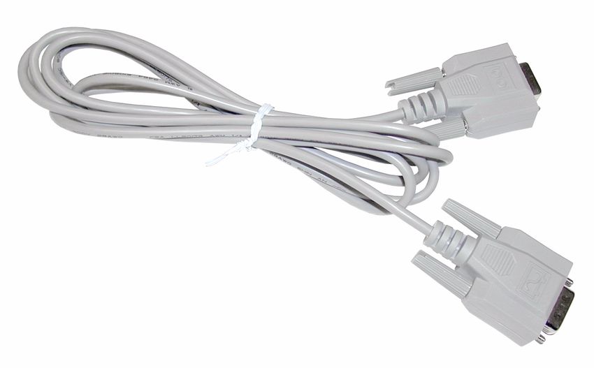
DNA-PPCx PowerDNA Cube
Chapter 1 1
Introduction
Chapter 1 Introduction
This document is intended to serve as a user manual for a PowerDNA Cube
system. It describes the PowerDNA Cube Distributed Network Acquisition sys-
tem, its components, specifications, and instructions for set up and operation.
PowerDNA is the umbrella name that describes a real-time distributed I/O sys-
tem with exceptional flexibility and performance. PowerDNA system consists of
three parts: (1) Input/Output Modules (a.k.a. I/O Modules, IOMs, Cubes) distrib-
uted throughout a process, large piece of equipment, facility, or other structure;
(2) Cubes connected via copper -or- fiber optic cables to (3) a host PC with a
dedicated Ethernet interface card and running Windows, Linux, or an RTOS.
Cubes may also be operated in stand-alone data-logger mode.
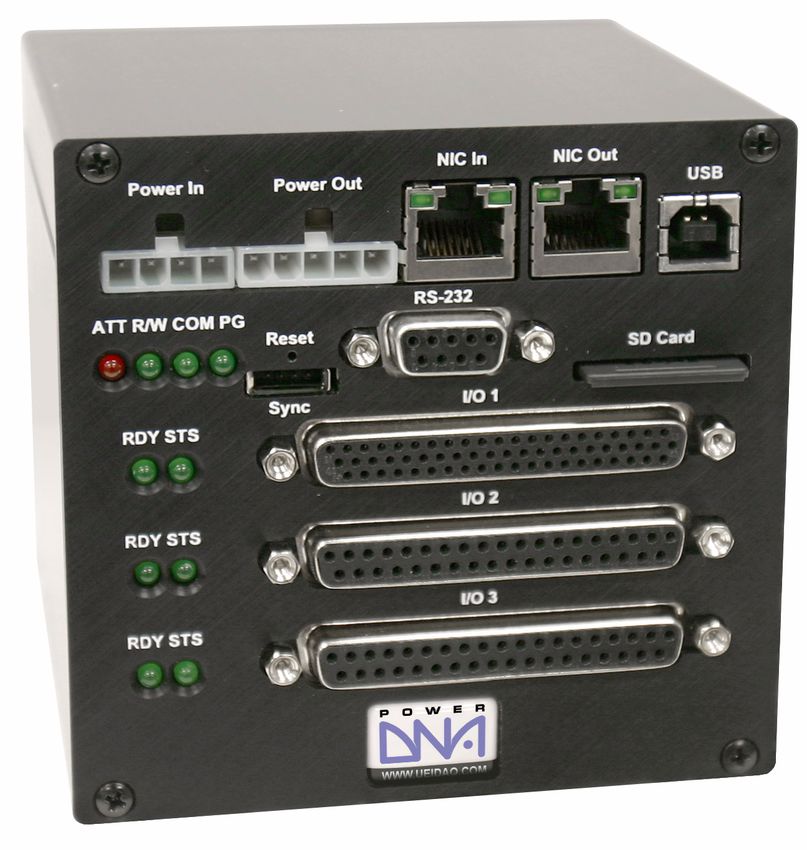
The PowerDNA Cube is available in either a 5- or 8-layer configuration. Two of
these layers are occupied by the Core Module. The Core Module consists of the
CPU Layer and the NIC (network-interface control) Layer, with connectors for
either 100Base-T copper or 100Base-FX fiber-optic cable. The remaining 3 or 6
slots in the Cube are factory-configured with your selection of I/O Layers. For
information on these data-acquisition layers, visit www.ueidaq.com.
This document gives further details about the features and functions of various
system components. Details on programming the system are contained in the
companion document(s): the PowerDNA API Reference Manual, and various
layer manuals.
Who should read this manual?
This manual has been written to make the installation, configuration, and opera-
tion of the PowerDNA cube as straightforward as possible. However, it
assumes that the user has basic PC skills and is familiar with the Microsoft Win-
dows XP/2000/ NT/9x, QNX or Linux/RTLinux/RTAI Linux operating environ-
ments.
Organization of this manual
This PowerDNA User Manual is organized as follows:
• Chapter 1—Introduction
An introduction to the cube.
• Chapter 2—Installation and Configuration
Provides instructions for installing and configuring the cube
• Chapter 3—The PowerDNA Explorer
Provides an overview of PowerDNA Explorer Main Window, menu bar,
toolbar, Device Tree, setting panel, IOM settings, and Device layer set-
tings.
• Chapter 4—PowerDNA Core Module
Describes the function and architecture of the CPU and NIC layers
• Chapter 5—Programming Layer-specific Functions
Describes device architecture, memory map, startup sequence, setting
parameters, updating firmware, common layer interface.
© Copyright January 2021 January 2021 www.ueidaq.com
United Electronic Industries, Inc.
508.921.4600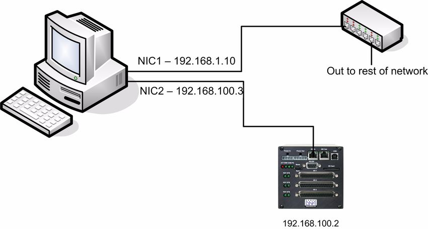
DNA-PPCx PowerDNA Cube
                                                                                                          Chapter 1            2
                                                                                                       Introduction

                                             •   Appendix
                                                 Provides an overview of how to determine the version of PowerDNA,
                                                 update the firmware, and configure the Ethernet card in various Win-
                                                 dows OS and Linux installations.
                                             •   Index
                                                 Alphabetical listing of the topics covered in this manual.

                                        NOTE: Refer to the DAQBIOS Protocol Manual for detailed information about
                                              Host / IOM Communication, how DAQBIOS works, the DAQBIOS
                                              Engine, Real-Time Operation with an IOM, and Asynchronous
                                              Operation with an IOM.

                                        Conventions
                                        To help you get the most out of this manual and our products, please note that
                                        we use the following conventions:

                                         Tips are designed to highlight quick methods to get the job done, or to
                                        reveal uncommon knowledge and ideas.

                                        NOTE: Notes alert you to important information.

                                        CAUTION! Caution advises you of precautions to take to avoid injury, data
                                        loss, or a system crash.

                                        Text formatted in bold typeface generally represents text that should be entered
                                        verbatim. For instance, it can represent a command, as in the following exam-
                                        ple: “Instruct operator of how to run setup using a command such as
                                        setup.exe”
                                        Other PowerDNA Documentation
                                        This PowerDNA User Manual is one part of the documentation set available for
                                        the PowerDNA system. We offer other resources you might want to read before
                                        programming an application. They are available either on the PowerDNA Soft-
                                        ware Suite CD or can be downloaded from the UEI web site.
                                        In particular, we recommend the PowerDNA API Reference Manual, Pow-
                                        erDNA Quick Start Manual, UEIDAQ Framework Reference Manual, UEIDAQ
                                        Framework User Manual, and the UEIDAQ Framework Getting Started Manual.
                                        Feedback
                                        We are interested in any feedback you might have concerning our products and
                                        manuals. Comments and recommendation can be sent by email to sup-
                                        port@ueidaq.com.

1.1        PowerDNA                     This chapter provides an overview of the key features of the PowerDNA sys-
           Overview                     tem, and how the system works.
                                        Thank you for purchasing a PowerDNA Cube system. We designed this product

© Copyright January 2021               January 2021                                                           www.ueidaq.com
  United Electronic Industries, Inc.
                                                                                                                508.921.4600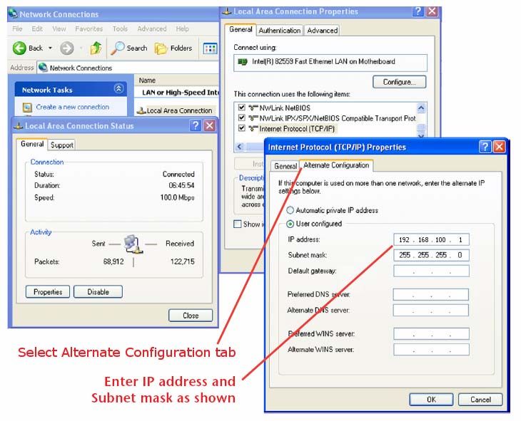
DNA-PPCx PowerDNA Cube
                                                                                                            Chapter 1            3
                                                                                                         Introduction

                                        family from the ground up to provide the best possible features, reliability, and
                                        performance at an economically sound price.

1.1.1        What’s in the              Inspect the package. Included you should find:
             Package

                                                              The PowerDNA Cube
                                                              Preinstalled with your selection of I/O Layers

                                                              DNA-PSU-series power supply (100-240V 50-60Hz to
                                                              24VDC)

                                                              Ethernet cable with either RJ-45 connector (for copper)
                                                              or SC-type (for fiber optic 100-Base-FX cable)

                                                              Serial cable (for initial configuration)

                                        Additional accessories may be included, depending on your order.

1.2        Overview                     The PowerDNA system consists of a hardware Cube and software suite. The
                                        software suite is located both on the PowerDNA / PowerDAQ CD shipped with
                                        the Cube and on the website: www.ueidaq.com
                                        The software that supports the system consists of two components:

                                                                                         PowerDNA low-level driver;
                                                                                         PowerDNA Explorer (and
                                                       PowerDNA Software Suite           demo);
                                                                                         Example code for C & Java
                                                                                         Additional example code & docs
                                                                                         for
                                                          UEIDAQ Framework               C/C++, C#, VB.NET, ActiveX (VB6, Del-
                                                                                         phi), MATLAB, LabVIEW, DASYLab,
                                                                                         LabWindows/CVI, OPC

                                        The Windows PowerDNA Software Suite contains the following software:
                                             •   PowerDNA low-level driver
                                                 The interface between the cube hardware and higher-level languages.

© Copyright January 2021               January 2021                                                            www.ueidaq.com
  United Electronic Industries, Inc.
                                                                                                                 508.921.4600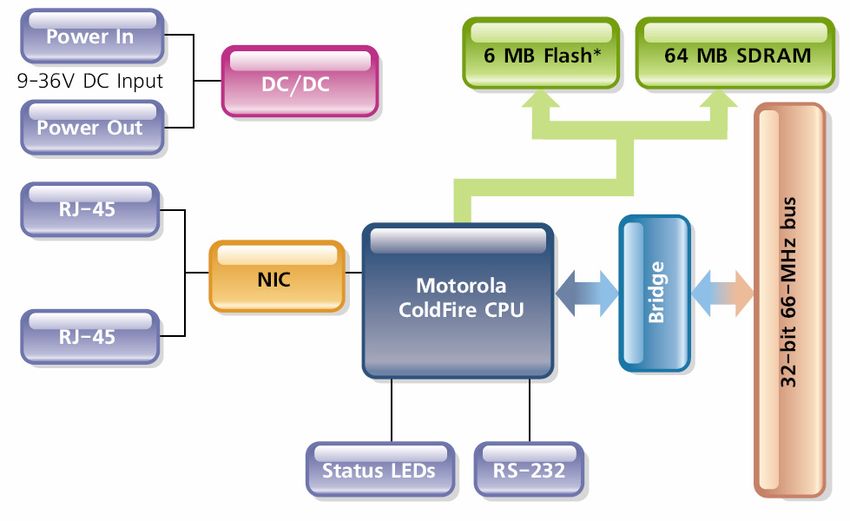
DNA-PPCx PowerDNA Cube
                                                                                                         Chapter 1            4
                                                                                                      Introduction

                                             •   PowerDNA Explorer
                                                 The essential tool for configuring and testing the cube. See Chapter 3
                                                 for use.
                                             •   Multi-Threaded TTY Client
                                                 For initial setup of the cube on the network, upgrades, and calibration.
                                             •   Example C & Java code
                                                 Facilitates jumping in and learning — this code will compile and execute
                                                 on the cube.
                                        In addition to the examples in the PowerDNA Software Suite, the UEIDAQ
                                        Framework contains example code for higher-level languages (C++, VB, Java),
                                        and also several graphical programming languages (e.g., LabVIEW,
                                        DASYLab).
                                        The framework facilitates and expedites test development: an experiment can
                                        be set up in less than twenty lines of code. The framework function calls are
                                        portable between programming languages.
                                        The Linux software package includes:
                                             •   DAQLib - Library for writing programs using PowerDNA IO modules
                                                 (cubes)
                                             •   UeiPalLib - Platform abstraction library needed for building the DAQLib
                                             •   DAQLib_Samples - Example programs demonstrating how to use the
                                                 DAQLib to work with various layer types
                                        Instructions on use can be found in the readme.txt of the package.
                                        The hardware / PowerDNA cube is composed of:
                                             •   External casing – in two compact sizes:
                                                 Core Module + 3 I/O Layers: 3.95” × 4.1” × 4.0”
                                                 Core Module + 6 I/O Layers: 5.8” × 4.1” × 4.0”
                                             •   Core Module [2 layers at the top]
                                                 -- The CPU Layer [PowerPC | Coldfire]
                                                    Integrated CPU with real-time kernel in firmware;
                                                    Cube can operate as a standalone unit

                                                 -- The NIC Layer [100BaseT | Fiber 100-Base-FX]
                                                    Can lLink cube to any PC over commercial Ethernet,
                                                    Daisychain 64 Cubes over one Ethernet network
                                             •   Optional I/O-layers (refer to www.ueidaq.com for details)
                                             •   Resolutions to 24 bits; read/write to a Cube’s I/O Layers every 1 msec
                                             •   Analog Input
                                                 -- High-gain & low-gain
                                                 -- Strain Gauge module
                                                 -- Simultaneous Sampling module
                                             •   Analog Output
                                                 with optional current/voltage booster add-in card

© Copyright January 2021               January 2021                                                          www.ueidaq.com
  United Electronic Industries, Inc.
                                                                                                               508.921.4600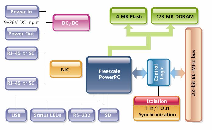
DNA-PPCx PowerDNA Cube
                                                                                                        Chapter 1          5
                                                                                                     Introduction

                                             •   Controller Area Network (CAN) Bus layer
                                             •   Counter-Timer
                                             •   Digital I/O
                                             •   Power-Conversion layer
                                        Chapter 2 details the configuration and operation of the cube’s Core Module.
                                        Chapter 4 details the behavior and architecture of the cube’s Core Module.
                                        Detailed information on the hardware layers is found in the layer-specific manu-
                                        als and on the website (www.ueidaq.com)

© Copyright January 2021               January 2021                                                      www.ueidaq.com
  United Electronic Industries, Inc.
                                                                                                           508.921.4600
DNA-PPCx PowerDNA Cube
Chapter 1 6
Introduction
1.3 Specifi- Figure 1-1 lists the Technical Specifications for the PowerDNA PPCx Cubes.
cations
Technical Specifications:
Standard Interfaces
To Host Computer 10/100Base-T, standard RJ-45 connector
Daisy chain output 10/100Base-T, standard RJ-45 connector
Config/General RS-232, 9-pin “D”
Sync Custom cable to sync multiple cubes
I/O Slots Available
DNA-PPC8 6 slots
DNA-PPC5 3 slots
Host Communications
Distance from host 100 meters max, CAT5 cable
Ethernet data 2 megabyte per second
transfer rate
Analog data up to 1 megasample per sec (16-bit samples)
transfer rate
DMAP I/O mode update 1000 I/O channels (analog and/or digital)
in less than 1 millisecond, guaranteed
Processor
CPU Freescale MPC5200, 400 MHz, 32-bit
Memory 128 MB (not including on-board Flash
Memory which contains OS kernel, I/O driv-
ers and firmware)
Status LEDs Attention, Read/Write, Power,
Communications Active
Environmental
Temp (operating) Tested to -40 °C to 85 °C
Temp (storage) -40 °C to 100 °C
Humidity 0 to 95%, non-condensing
Vibration
(IEC 60068-2-64) 10–500 Hz, 5 g (rms), Broad-band random
(IEC 60068-2-6) 10–500 Hz, 5 g, Sinusoidal
Shock
(IEC 60068-2-27) 50 g, 3 ms half sine, 18 shocks at 6 orientations;
30 g, 11 ms half sine, 18 shocks at 6 orientations
Altitude 70,000 feet, maximum
Physical Dimensions
DNA-PPC5 4.1” x 4.0” x 4.0”
DNA-PPC8 4.1” x 4.0” x 5.8”
Power Requirements
Voltage 9 - 36 VDC (AC adaptor included)
Power Dissipation 4 W at 24 VDC (not including I/O boards)
Figure 1-1 DNA-PPCx Cube Specifications
© Copyright January 2021 January 2021 www.ueidaq.com
United Electronic Industries, Inc.
508.921.4600DNA-PPCx PowerDNA Cube
Chapter 1 7
Introduction
1.4 DC Power Table 1-1 below describes the DC power thresholds for DNA-PPCx PowerDNA
Thresholds Cubes.
Table 1-1. DC Power Thresholds for DNA-PPCx Cubes
Backplane
Power Rail
Voltage Turn-on, V1 Reset, V Turn-off, V2 Notes
Logic Power +3.3V, +2.5V 8.8 8.4 7.7
Supply
Analog Power +24V 8.5 – 7.8
Supply
Fan Power +12V 8.8 – 8.4
Supply
On-layer +VIn 7.8 to 8.8 – 7.5-8.5 Varies with the
DC/DCs that layer used.
use input power
1. Turn-on, V: The value of Vin at which corresponding DC/DCs turn on.
2. Turn-off, V: The value of Vin at which corresponding DC/DCs turn off.
NOTE: A DNA-PPC core module consumes only 240mW when Vin is below 7.7V.
© Copyright January 2021 January 2021 www.ueidaq.com
United Electronic Industries, Inc.
508.921.4600DNA-PPCx PowerDNA Cube
Chapter 2 8
Installation and Configuration
Chapter 2 Installation and Configuration
Installation consists of:
• PowerDNA software package installation
• Cube hardware setup
• Configuration
2.1 Initial This section outlines the steps to be taken in Section 2.2.
Installation -
Overview
STEP 1: Install the PowerDNA software suite. The latest software suite can be found
online at www.ueidaq.com/download; a copy is also included on the CD.
STEP 2: Connect the serial cable: from Cube RS-232 port to the host computer serial port
a. Start a TTY client:
Start >> Programs >> UEI >> PowerDNA >> MTTTY
b. Change the Baud rate to 57600 and Click Connect.
STEP 3: Connect the power supply to the Cube.
STEP 4: The Cube comes pre-configured with an IP address. Using MTTTY, type
[Enter] to test the prompt, for Coldfire: DQ> for PPC: =>. Then type:
DQ> show
ip: 192.168.100.2
netmask: 255.255.255.0
STEP 5: (optional) The recommended method of connection to the Cube is via a direct
Ethernet cable connected to an external NIC. Connecting the cube directly to a
LAN usually requires a change of IP address on the Cube. For example, your
system administrator has assigned you the unused IP, 192.168.0.65. Here is
how to change the IP to this example IP:
DQ> set ip // Sets this Cube’s IP to 192.168.1.10
192.168.0.65 // Saves the newly changed configuration
DQ> store // Reboots the cube for the new IP to take
DQ> reset // effect
To make sure that the PowerDNA Cube is alive, ping it:
C:\> ping –n 1 192.168.0.65
STEP 6: Use PowerDNA Explorer for graphical configuration (see Chapter 3).
© Copyright January 2021 January 2021 www.ueidaq.com
United Electronic Industries, Inc.
508.921.4600DNA-PPCx PowerDNA Cube
Chapter 2 9
Installation and Configuration
2.2 Initial This section reviews how to perform an initial hardware and software setup
Installation – when you first receive a PowerDNA Cube.
Start-to-finish
Guide
2.2.1 Inspect the Inspect the contents of the shipping package. With a standard PowerDNA
package Cube, you should find:
• The PowerDNA Cube itself, preinstalled with your selection of I/O Lay-
ers.
• The DNA-PSU-24 universal powerline brick, which plugs into an outlet
and provides 24V dc output. The supply comes with a plug for the
mains, an adapter cable ending in a Molex connector for plugging into
the DNA Cube, and a daisychaining cable for supplying additional
Cubes with power from the same supply (max. of three Cubes total).
• Serial cable for initial hardware configuration and firmware download-
ing.
• CD-ROM with support software
2.2.2 Install This section describes how to load the PowerDNA software suite onto a Win-
Software dows- or Linux-based computer and run some initial tests.
The latest PowerDNA support software is online at www.ueidaq.com/download;
a known working copy is also on the PowerDNA Software Suite CD.
A. Software Install: Windows 9x/2000/XP
The PowerDNA CD provides two installers:
• PowerDNA Software Suite: low-level driver and PowerDNA tools
• UEIDAQ Framework: high-level programming examples (optional)
Both installers automatically search for third-party IDE and testing suites, and
add themselves as tools to the found suites. Install third-party applications (e.g.,
LabVIEW, MsVS2003) before installing the PowerDNA Software Suite or
UEIDAQ Framework.
To install the PowerDNA Software Suite, do the following:
STEP 1: Log in as Administrator.
STEP 2: Run Setup.
a. Insert the PowerDNA Software Suite CD into your CD-ROM drive.
Windows should automatically start the PowerDNA Setup program. An
installer with the UEI logo and then PowerDNA Welcome screen should
appear. If none appears, run setup.exe from the CD drive:
Start >> Run >> d:\setup.exe >> OK.
If you downloaded the most recent executable from www.ueidaq.com,
double-click to run the executable.
b. Choose the PowerDNA Software Suite option.
c. Unless you are an expert user and have specific requirements, we
advise you to select Typical installation and accept the default
© Copyright January 2021 January 2021 www.ueidaq.com
United Electronic Industries, Inc.
508.921.4600DNA-PPCx PowerDNA Cube
Chapter 2 10
Installation and Configuration
configuration. The Software Suite installer requires and automatically
installs Sun’s Java VM (JRE) for you, in addition to the full complement
of tools. As an alternative, use the custom option to display and ensure
that all of the packages necessary are installed.
d. Companion Documentation:
Quick Start Guide, Configuration & Core Module,
I/O Layer Manuals, Low-level Programming Guide
e. SDK: includes/lib for C/Java, examples, and Sun’s JRE;
(The SDK is not the UeiDaq Framework).
f. PowerDNA Apps: PowerDNA Explorer, MTTTY
g. PowerDNA Components (incl. DLL files)
h. PowerDNA Firmware
i. Click Next to continue through the dialogs.
j. Click Finish to complete installation; restart the computer.
This Software Suite installed the bare-minimum tools needed in later steps:
MTTTY, PowerDNA Explorer, and the low-level driver.
UEIDAQ Framework provides the structure for developing applications under
C/C++, C#, VB.NET, ActiveX (VB6, Delphi), MATLAB, LabVIEW, DASYLab,
LabWindows/CVI, OPC, and other programming languages.
NOTE: Because the installation process modifies your Windows registry, you
should always install or uninstall the software using the appropriate
utilities. Never remove PowerDNA software from your PC directly by
deleting individual files; always use the Windows Control Panel/Add-
Remove Programs utility.
B. Software Install: Linux
Linux: The PowerDNA_*.tgz file in the CD\Linux folder contains the software
package for Linux. To extract the file to a local directory, enter:
tar -xjvf /path/to/powerdna*.tgz
Follow the instructions in the readme.txt contained therein.
© Copyright January 2021 January 2021 www.ueidaq.com
United Electronic Industries, Inc.
508.921.4600DNA-PPCx PowerDNA Cube
Chapter 2 11
Installation and Configuration
2.2.3 Initial Boot-up This procedure is needed to prepare for network configuration. Do the following
steps:
STEP 1: Familiarize yourself with front-panel layout. Note that all connections are made
on front of the unit; no rear access is required in a rack-mounted configuration).
STEP 2: Attach the serial cable to the host PC and to the DNA Cube RS-232 port.
a. Run a terminal-emulation program (MTTTY) on the PC. Any terminal-
emulation program may be used (MTTTY, Minicom, TeraTerm, etc.)
Note that Hyper Terminal probably will not work with a PowerDNA Cube.
b. Verify that COM parameters are set: 57600 baud, 8 bits, no parity, 1 stop
bit.
c. Click Connect in MTTTY, or use the commands on one of the other
terminal-emulation programs to establish communication with the Cube.
STEP 3: Power up the Cube (9-36V DC) by attaching the Molex-type power connector
leading from the bundled DNA-PSU-24, a user-supplied source, or a
daisychained line from another PowerDNA Cube. Note that the DNA-PSU-24
plugs into a 100-240V, 50/60-Hz outlet. Also note that the Cube does not have
an On/Off switch.
STEP 4: As soon as the Cube powers up, it runs through self-diagnostic mode and
generates output on the terminal program. A typical readout might be:
Figure 2-1 Typical MTTTY Startup Screen
The boot process displays the model, serial number, and position of layers.
© Copyright January 2021 January 2021 www.ueidaq.com
United Electronic Industries, Inc.
508.921.4600DNA-PPCx PowerDNA Cube
Chapter 2 12
Installation and Configuration
Type show to display information about cube configuration:
DQ> show // IOM or I/O Module – is another
name: "IOM_1234" // name for a Cube
model: 0x1005 // Core Module > Model Number (1005:
// ColdFire)
serial: 0012345
// Core Module > Serial Number (S/N)
mac: // of Cube
00:00:11:AA:BB:CC
//Core Module > NIC Layer > MAC
fwct: 1.2.0.0 // Address
srv: // Define Cube procedure on startup
192.168.100.3
// IP Address of firmware server
ip:
192.168.100.2 // IP Address of this Cube
gateway: // IP Address of gateway
192.168.100.1 // IP Subnet Mask of this Cube
netmask: // UDP Port to receive commands on
255.255.255.0
udp: 6334
All parameters can be changed; most notably, the cube’s configured IP, gate-
way, and subnet mask (netmask).
2.2.4 IP Addresses The PowerDNA Cube ships with a preconfigured factory default IP address in
on the nonvolatile memory (usually 192.168.100.2). This is a static IP address; the
PowerDNA PowerDNA Cube never retrieves its IP address from a DHCP server.
Cube This section describes why and how to change the default IP address.
Should you change the IP?
Yes, if you plan to use the Cube on a LAN where.
• High sampling rate is not necessary
• Some samples may be dropped due to network congestion and colli-
sions
• The cube should be accessible by multiple parties on the LAN
• Multiple Cubes operate (and interact) on the same network
Alternatively, if you plan to use the Cube for high-speed measurements where
reliability is necessary – a direct connection between the host PC and a NIC1 is
recommended. For a direct connection, see the following section, “Improving
Network Performance”
How to change the IP.
Both PowerDNA Explorer and a terminal-emulation program can change the IP.
Consult your system or network administrator to obtain an unused IP. Let’s say,
for example, that your system administrator assigns you the IP 192.168.0.65.
To change the IP from the terminal program, enter the following commands:
1. NIC - Network Interface Controller; a commercially available Ether-
net
(i.e. IEEE 802.3) adapter.
© Copyright January 2021 January 2021 www.ueidaq.com
United Electronic Industries, Inc.
508.921.4600DNA-PPCx PowerDNA Cube
Chapter 2 13
Installation and Configuration
DQ> set ip // Sets this Cube’s IP to 192.168.0.65
192.168.0.65 // The default password is “powerdna”
Enter user password
> powerdna // Saves the newly changed configuration
DQ> store // Reboots the cube for the new IP to
DQ> reset //take effect
You can set any parameters listed with the “show” command in this manner.
Connect the PowerDNA Cube to your switch with the bundled CAT5e cable.
If you can establish communications with a Cube, but later want to modify the
IP address, you can also do so from within PowerDNA Explorer. After the
exploratory process, go to the field where the application displays the IP
address. Enter the new IP address and then hit . This action down-
loads the new IP address into the Cube’s non-volatile memory. You might also
need to change the gateway and network mask to match settings on your LAN.
2.2.5 Improving To improve PowerDNA network performance, we recommend that you use a
Network separate commercially available network interface controller (NIC) card and set
Performance up a dedicated mini-network for PowerDNA.
The goal of this section is to facilitate creation of such a network:
For example, assume that your office uses a Class C network (the class
intended for small networks with fewer than 256 devices) and your host is con-
figured with a static IP or via DHCP—Dynamic Host Configuration Protocol — a
protocol for assigning dynamic IP addresses to devices on a network.
STEP 1: Obtain your networking configuration by using the Command Prompt:
Start>>Programs>>( Accessories>>) Command Prompt
C:\> ipconfig
Ethernet adapter NIC1 - Local Area Connection:
© Copyright January 2021 January 2021 www.ueidaq.com
United Electronic Industries, Inc.
508.921.4600DNA-PPCx PowerDNA Cube
Chapter 2 14
Installation and Configuration
Connection-specific DNS Suffix :
IP Address. . . . . . . . . : 192.168.1.10
Subnet Mask . . . . . . . . . . . : 255.255.255.0
Default Gateway . . . . . . . . . . : 192.168.1.1
Linux users can use the more verbose “ifconfig” command instead.
Here, the subnet range 192.168.1.0-192.168.1.255 is being used by NIC1.
IP Addressing:
The range of usable addresses is defined by the IP
address and subnet mask. An IP address is a number
that is split into the range of 0.0.0.0 and
255.255.255.255. Here, the IP address is
192.168.1.10.
The subnet mask indicates where an address stops.
For example, a subnet mask 255.255.255.240 has 15
usable addresses (255.255.255.255 –
255.255.255.240).
Here, the subnet is 255.255.255.0, or 255
addresses.
The subnet limits from anything.anything.anything.0
up to the max.
The usable range for 192.168.1.10/255.255.255.0 is
192.168.1.1 to 192.168.1.254 (192.168.1.0 and
192.168.1.255 are reserved for Router and Broadcast
messages).
The usable range for 192.168.0.4/255.255.0.0 is
192.168.0.1 to 192.168.255.255
The usable range for 192.168.100.2/255.255.255.0 is
192.168.100.1 to 192.168.100.254
Not every IP address from 0.0.0.0 to
255.255.255.255 is usable; however, these three
ranges of IP addresses are guaranteed open for
private use:
10.0.0.0 – 10.255.255.255
172.16.0.0 – 172.31.255.255
192.168.0.0 – 192.168.255.255
You need not use the entire set.
STEP 2: Install the secondary NIC card.
STEP 3: Set up a network that does not overlap the existing one.
The address space 192.168.1.0 – 192.168.1.255 is used. The IP address
block, 192.168.2.1 – 192.168.2.255 is available and in the private range.
Let us choose 192.168.100.1 – 192.168.100.255 for the PC’s secondary NIC:
IP: 192.168.100.3
Netmask: 255.255.255.0
Gateway:192.168.100.3
Using the Network (Connections) in the control panel:
Start >> Programs >> Control Panel >>Network (Connections)
Right-click the adapter to bring up the properties window.
Open the TCP/IP properties of the adapter and edit to your liking.
© Copyright January 2021 January 2021 www.ueidaq.com
United Electronic Industries, Inc.
508.921.4600DNA-PPCx PowerDNA Cube
Chapter 2 15
Installation and Configuration
NOTE: Refer to the Appendix at the end of this document: “Configuring a
Second Ethernet Card” for step-by-step instructions on how to do this.
STEP 4: Confirm the network configuration at the Command Prompt:
Start >> Programs >> (Accessories >> ) Command Prompt
C:\> ipconfig
Ethernet adapter NIC1 - Local Area Connection:
Connection-specific DNS Suffix . :
IP Address. . . . . . . . . . . . : 192.168.1.10
Subnet Mask . . . . . . . . . . . : 255.255.255.0
Default Gateway . . . . . . . . . . : 192.168.1.1
Ethernet adapter NIC2 - Local Area Connection 2:
Connection-specific DNS Suffix . :
IP Address. . . . . . . . . . . . : 192.168.100.3
Subnet Mask . . . . . . . . . . . : 255.255.255.0
Default Gateway . . . . . . . . . : 192.168.100.3
STEP 5: Set up the PowerDNA Cube to use the same subnet, namely:
Cube IP: 192.168.100.2 // this is the factory default
Gateway:192.168.100.3
Netmask: 255.255.255.0
To do this from a serial terminal-emulation program, enter the following com-
mands when you get the DQ command prompt:
DQ> set ip // Sets this Cube’s IP address to
192.168.100.2 // 192.168.100.2
// Sets this Cube’s Gateway to
DQ> set gateway // 192.168.100.3
192.168.100.3 // Sets the subnet mask to 255.255.255.0
DQ> set netmask
255.255.255.0 // Saves the newly changed configuration
DQ> store // Reboots the cube for the new IP to
DQ> reset take
// effect.
STEP 6: Connect the PowerDNA Cube to your PC’s second NIC, using the bundled
CAT5 cable. The green lights should light up (try the other port, otherwise).
STEP 7: Ping the cube to make sure that it is alive.
C:\> ping –n 1 192.168.100.2
Pinging 192.168.100.2 with 32 bytes of data:
Reply from 192.168.100.2: bytes=32 timeDNA-PPCx PowerDNA Cube
Chapter 2 16
Installation and Configuration
STEP 8: The Cube should now be configured as follows, where NIC1 uses a straight-
through, and NIC2 uses a cross-over cable to the NIC In (or a straight-through
cable will connect to NIC Out).
STEP 9: You may now use PowerDNA Explorer to access the cube. See Chapter 3.
2.2.5.1 Trouble- The following checklist may assist you in troubleshooting a Cube.
shooting
The PG (Power Good) LED is on: the Cube plugged in using 9-36V DC.
The green lights on NIC In or NIC Out are blinking: CAT5e cable is
connected
Use the command prompt to ping (e.g., ping 192.168.100.2)
a. Disable (temporarily) the firewall on the secondary NIC.
b. Check the secondary NIC network settings.
c. Check the cube’s network settings.
Use MTTTY and hit Connect.
Press [Enter] to display the DQ> or => prompt.
(No prompt indicates that you are not connected)
Verify that the serial cable is firmly connected to the RS-232 port.
Verify the settings: 57600 baud, no parity, 8 data bits, 1 stop bit.
Try COM1, COM2, COM3 then hit Connect and press [Enter].
Reboot the cube. The start-up screen should display upon restart.
If all else fails, contact UEI support at: support@ueidaq.com
Type “show” to verify the Cube’s IP, Subnet Mask, and Gateway
© Copyright January 2021 January 2021 www.ueidaq.com
United Electronic Industries, Inc.
508.921.4600DNA-PPCx PowerDNA Cube
Chapter 2 17
Installation and Configuration
Ensure that the computers are on a valid subnet and have valid IPs
Finally – contact UEI for support at: support@ueidaq.com
2.2.6 PowerDNA PowerDNA Explorer does just what its name implies: it “explores” the LAN,
Explorer looking for connected PowerDNA Cubes. Chapter 3 covers the PowerDNA
Quick-Start Explorer in detail. This section/page only provides a quick-start guide.
The PowerDNA Explorer identifies PowerDNA Cubes on a selected network –
the discovered Cubes are listed on the left-hand-side pane. Select a cube to
display pertinent hardware and firmware information. Select a layer of a specific
cube to manipulate its inputs or outputs. In brief, this useful tool lets you verify
that the Cube is communicating with the host and that the I/O Layers are func-
tioning properly.
To scan the network for PowerDNA Cubes, provide a set of addresses to scan.
Do the following:
STEP 1: Select Network >> Address Ranges from the menu:
Figure 2-2 PowerDNA Explorer Startup Screen
STEP 2: Add the IP address of the PowerDNA Cube (e.g., 192.168.100.2); click Done.
STEP 3: Now scan the LAN for PowerDNA Cubes: Network >> Scan Network
One or more gray cube-like icons will display in the left-hand-side of the cube. If
no cube icons are displayed, see the Troubleshooting note in the previous sec-
tion.
© Copyright January 2021 January 2021 www.ueidaq.com
United Electronic Industries, Inc.
508.921.4600DNA-PPCx PowerDNA Cube
Chapter 2 18
Installation and Configuration
STEP 4: Double-click a cube to see its information and list the layers:
The screenshot above is from the PowerDNA Explorer Demo. The “demo” is
just a simulator for users without cubes – or for new users who want to explore
the PowerDNA Explorer program without reading/writing to real hardware. Run
this program and hover your mouse over the buttons to read the tool-tips and
learn through interacting with the program.
Some quick notes:
To use the layer, the “Enabled” check box should be set.
To read from a layer, click the second-to-last button: “Read Input Data”
To write to the layer, change the value and click the third (or fourth) button
with the red arrow on top of the cube: “Store Configuration”. The cube with
the blue arrow above it restores the configuration.
To change the IP, change the number, deselect the field, and “Store
Configuration”. Take care not to set the IP Address to outside of the
network’s configuration subnet -or- to an IP address that is currently in
use, as the cube will then become unreachable.
See Chapter 3, PowerDNA Explorer, for additional information and instruction.
© Copyright January 2021 January 2021 www.ueidaq.com
United Electronic Industries, Inc.
508.921.4600DNA-PPCx PowerDNA Cube
Chapter 2 19
Installation and Configuration
2.2.7 Updating Firmware in a PowerDNA Cube’s CPU layer stores configuration data, along
Firmware with a user application (user-app is compiled on a host PC).
Updated firmware is periodically released to introduce new features and to
improve the performance of existing features. Updated releases of the firmware
are bundled with the entire PowerDNA Software Suite, available for download
at any time from the UEI web site (www.ueidaq.com).
CAUTION!
If you update the firmware in a Cube, be sure to use the
PDNA Explorer from the same release as that new firmware.
After installing the PowerDNA Software Suite, browse to the installation’s Firm-
ware directory (e.g. C:\Program Files\UEI\PowerDNA\Firmware).
The directory may contain MTTTY, updated firmware installation instructions
“FirmwareInstall.html,” and two sub-directories containing the firmware.
Choose the sub-directory corresponding to the architecture of your cube:
ColdFire (CF/CM) with extension S19, or PowerPC (PPC), with extension MOT.
Determining the version of your PowerDNA cube with PDNA Explorer:
Before updating the firmware of a PowerDNA cube, check the cube
version to determine which update method to use.
a. Supply power to the PowerDNA cube.
b. Connect the PowerDNA cube to its network.
c. Start PowerDNA Explorer on the Microsoft Windows desktop from
Start >> Programs >> UEI >> PowerDNA >> PowerDNA Explorer
d. Choose Network Scan Network
e. Select the PowerDNA cube you wish to query (by clicking the cube).
f. The version is given in the FW Ver field.
If the FW Ver field has is version 2.x.x, or 3.x.x (let x be any version number),
you should follow the Firmware Update Instructions [CM5, CM8] section below.
For other versions of firmware (e.g., 1.x.x), refer to the user manual on the CD
that accompanied your device when you purchased it.
© Copyright January 2021 January 2021 www.ueidaq.com
United Electronic Industries, Inc.
508.921.4600DNA-PPCx PowerDNA Cube
Chapter 2 20
Installation and Configuration
2.2.8 Firmware Before using a new release of the libraries and applications to communicate
Update with your PowerDNA cube, you must install the latest version of the firmware on
Instructions the PowerDNA cube. The version of the firmware must correspond to the ver-
sion of the PowerDNA Software Suite — mismatched versions cause an error.
Instructions for updating the PowerDNA Cube via PowerDNA Explorer (over an
Ethernet LAN line), and over an MTTTY (serial line) follow.
To upload firmware with PowerDNA Explorer over LAN, do the following:
STEP 1: Supply power to the PowerDNA cube.
STEP 2: Connect the PowerDNA cube to its network.
STEP 3: Start PowerDNA Explorer on the Microsoft Windows desktop from
Start >> Programs >> UEI >> PowerDNA >> PowerDNA Explorer
STEP 4: Choose Network >> Scan Network
STEP 5: Select the PowerDNA cube to be updated.
STEP 6: Select Network >>Update Firmware…from the menu.
Figure 2-3 Update Firmware Menu Item
STEP 7: Click on “Yes” when you see the prompt:
“Are you sure you want to update firmware…”
STEP 8: Double-click on the dq_ram.S19 file.
STEP 9: Enter the password to continue. More information about passwords can be
found in the “Interfacing to the CM module using a serial interface” section of this
manual. PowerDNA cubes come with the default password set to powerdna.
powerdna
Figure 2-4 Password Dialog Box
© Copyright January 2021 January 2021 www.ueidaq.com
United Electronic Industries, Inc.
508.921.4600DNA-PPCx PowerDNA Cube
Chapter 2 21
Installation and Configuration
STEP 10: Wait for the progress dialog to complete. The PowerDNA cube will then be
updated and running the new firmware.
Figure 2-5 Firmware Update Progress Dialog Box
Each cube is updated in three steps. First, the firmware is transferred to the
cube. Second, the firmware is written to the flash memory. During this step, the
R/W light on the front of the cube is lit, in addition to the PG light. Third, the
cube is reset. During this step, the ATT, COM, and PG lights are lit, and the R/W
light will turn on and off periodically. When the cube is finished resetting, only
the PG light is lit.
To upload firmware over serial port using a terminal client (MTTTY, do the fol-
lowing):
Under DNA-CM5 and DNA-CM8:
STEP 1: Establish communications between the PC and a Cube over the serial link.
STEP 2: Press the Hardware Reset switch on the front of the Cube to reset the CPU
Layer.
STEP 3: While the Cube is starting up again, press + to activate the download
screen (indicated by a #> prompt).
If you get to the DQ> prompt, you waited too long and must return to Step 2.
STEP 4: Enter the dl command to enter the firmware-download routine.
STEP 5: Transfer the file. Depending on which terminal-emulation package you decide to
run, you usually initiate the download with a command similar to “send”. In
MTTTY, go to the top menu and select Transfer >>Send file (text). When it asks
for a file, go to the PowerDNA\Firmware directory and select the .S19 or .MOT
firmware file. The download procedure will take roughly a minute.
STEP 6: To tell the Cube to save the new firmware into EPROM, enter the commands
upuser
update
STEP 7: Enter go to complete the firmware-update procedure and return to the DQ>
prompt.
Under DNA-PPC5 and DNA-PPC8:
STEP 1: Establish communications between the PC and a Cube over the serial link.
STEP 2: Press the hardware Reset switch on the front of the Cube to reset the CPU
Layer, or type: reset all
STEP 3: While the Cube is starting up again, Press ESC to go into u_boot.
STEP 4: Type the command to erase firmware download area in the Flash memory:
© Copyright January 2021 January 2021 www.ueidaq.com
United Electronic Industries, Inc.
508.921.4600DNA-PPCx PowerDNA Cube
Chapter 2 22
Installation and Configuration
=> erase all
=> loads romimage.mot// loads stores firmware into the flash while
// downloading it.
STEP 5: Transfer the Motorola firmware file. Use Transfer » Send File, and select
\Program Files\UEI\PowerDNA\ Firmware_PPC\romimage_3_x_y.mot
A progress bar will appear in the lower left corner of MTTTY indicating progress.
STEP 6: Wait for the upload to complete (it may take a few minutes).
STEP 7: After the process finishes, enter the fwjmp command. The PowerDNA cube will
then be updated and running the new firmware. At this point, only the PG light
on the cube remains lit.
2.3 Mounting and Mount the Cube directly to the application hardware either by screwing it
field directly to the machine or by using the optional DIN rail clip (DNA-DR). A nor-
connections mal DIN rail comes with screws you can use to mount the rail onto another sur-
face or piece of equipment. However, because the Cubes are designed to fit
into applications where space is at a premium, it may sometimes be difficult to
attach the rail in this way. For such cases, we include a special adhesive tape
for attaching the rail to any desired surface.
CAUTION! Take care when deciding on which surface you plan to mount a
Cube. For example, using the adhesive strip, you can normally attach the
DIN rail to a wall without causing any damage, as shown below — unless
the wall has a sensitive coating such as delicate paint or wallpaper.
© Copyright January 2021 January 2021 www.ueidaq.com
United Electronic Industries, Inc.
508.921.4600DNA-PPCx PowerDNA Cube
Chapter 2 23
Installation and Configuration
2.4 Wiring 100BaseTX/100BaseFX Wiring Configurations
Typical wiring configurations for 100BaseTX/100BaseFX networks are shown in
the following figures.
Cubes may also be connected with standard straight-through lines through a
switch.
Alternatively, a cross-over cable may be used to directly connect to a cube, as
shown below. This improves performance (and isolates the cube from problems
with the switch).
For a fast connection in the field, you may connect a straight through cable to
the NIC Out jack, as shown below. Use the NIC In jack to connect out to the
LAN. The reason that this works is that in the NIC Out jack, the Rx/Tx lines are
© Copyright January 2021 January 2021 www.ueidaq.com
United Electronic Industries, Inc.
508.921.4600DNA-PPCx PowerDNA Cube
Chapter 2 24
Installation and Configuration
crossed over for you, so the wiring acts like a cross-over cable for you.
A crossover cable is the same as a straight-through except the Rx/Tx lines are
inverted, as shown below:
NOTE: The above configurations work with CM and PPC (not FCM, or FPPC)
when used in conjunction 8-wire Category 5 copper cabling (i.e. CAT5/
CAT5e) less than 100meters in length, and a 10/100Mbit NIC, or switch.
© Copyright January 2021 January 2021 www.ueidaq.com
United Electronic Industries, Inc.
508.921.4600DNA-PPCx PowerDNA Cube
Chapter 2 25
Installation and Configuration
For FCM and FPPC cubes, use a fiber NIC, as shown below:
In this diagram, NIC1 is a copper NIC connecting the PC to the LAN (optional).
NIC2 is an Intel network card in the PC used to connect to the cube’s built-in
fiber ports. A multi-mode optical cable with SC-type plugs like this one is used
to connect to the Tx/Rx plugs. In 100Base-FX mode, the maximum transmis-
sion range (without a repeater) is 2km at full-duplex, or 400m at half-duplex.
The cube uses an HFBR-5803 transmitter capable of communication at
100Mbps.
2.5 Peripheral Refer to the companion layer manuals for proper wiring to layers.
Terminal
Panel Wiring
© Copyright January 2021 January 2021 www.ueidaq.com
United Electronic Industries, Inc.
508.921.4600DNA-PPCx PowerDNA Cube
Chapter 3 26
PowerDNA Explorer
Chapter 3 PowerDNA Explorer
PowerDNA Explorer simplifies configuration and setup of a PowerDNA cube
under Microsoft Windows.
This section describes the various menus in PowerDNA Explorer.
NOTE: The PowerDNA Explorer DEMO lets you safely explore the menus and
layer screens without the need for using actual PowerDNA cubes.
3.1 The Main The Main Window of the PowerDNA Explorer is shown in Figure 3-1.
Window
Figure 3-1 PowerDNA Explorer Main Window
The Main Window is the window you see when the PowerDNA Explorer is first
launched and is where you do most of your work. It has four main parts: the
Menu Bar, the Toolbar, the Device Tree, and the Settings panel.
3.2 Menu Bar The Menu Bar contains the following menus and menu items.
3.2.1 File Menu Preferences brings up the preferences dialog.
The preferences dialog allows you to specify the network timeout interval. This
is the length of time PowerDNA Explorer will wait for response from a Pow-
erDNA cube before giving up with an error. It defaults to 100 milliseconds.
Figure 3-2 Preferences
Exit exits the application. If there are unsaved device settings changes, you are
prompted for confirmation.
3.2.2 Network Menu Address Ranges brings up the Address Ranges dialog, allowing you to specify
© Copyright January 2021 January 2021 www.ueidaq.com
United Electronic Industries, Inc.
508.921.4600DNA-PPCx PowerDNA Cube
Chapter 3 27
PowerDNA Explorer
where to scan for devices.
Figure 3-3 Address Ranges Dialog Box
The Address Ranges dialog allows you to specify the IP addresses and UDP
port to use to find devices. You can specify individual addresses as well as
address ranges. The specified items appear in a list that can be added to and
deleted from. This list defaults to a single range item that specifies the range
192.168.100.2 ... 192.168.100.10.
Figure 3-4 Edit Address Ranges Dialog Box
Scan Network scans the network for devices and populates the device tree.
How much of the network is scanned depends on the settings in the Network
© Copyright January 2021 January 2021 www.ueidaq.com
United Electronic Industries, Inc.
508.921.4600DNA-PPCx PowerDNA Cube
Chapter 3 28
PowerDNA Explorer
Ranges dialog.
Figure 3-5 After a Network >>Scan Network
If you choose Scan Network when the device tree is already populated, any
new devices discovered will be added to the tree. Any existing devices that are
missing will be removed from the tree, unless you have made unsaved changes
to such a device's configuration, in which case it will be marked in the tree as
missing.
Reload Config re-reads the configuration of the current device selected in the
Device Tree. If you have made changes to the settings in the settings panel for
the current device, Read will replace those settings with the device's current
settings, after prompting for confirmation.
Store Config writes the currently selected device's changed settings to the
device. The button is disabled for devices that haven't been modified.
Store All Configs writes all of the changed devices' settings to the devices.
The button is disabled if no devices have been modified.
Read Input Data is enabled when the currently selected device is an input
device layer. It reads the current input values to the device and causes them to
be displayed in the settings panel.
Update Firmware… loads a firmware update file to all connected PowerDNA
cubes if Host PC is selected. It updates only one PowerDNA cube when the
specific PowerDNA cube is updated. More details about this can be found in the
section Updating firmware in a version 2.0 PowerDNA cube.
Note that writing certain configuration changes to a PowerDNA cube running
firmware 2.0.16 will bring up a password dialog box. More information about
passwords can be found in the “Interfacing to the CM module using a serial
interface” section of this manual. PowerDNA cubes come with the default pass-
word set to “powerdna”.
© Copyright January 2021 January 2021 www.ueidaq.com
United Electronic Industries, Inc.
508.921.4600You can also read