Draught beer quality manual - Prepared by the Technical Committee of the Brewers Association
←
→
Page content transcription
If your browser does not render page correctly, please read the page content below
brewers association

                            draught beer
                          quality manual

Prepared by the
Technical Committee of
the Brewers Association
SECOND EDITION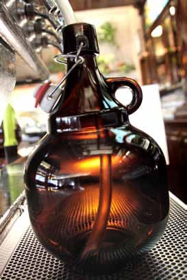
preface
t     he Draught Beer Quality working group was
      formed in March 2007 under the direction of
      the Brewers Association Technical Committee.
Our overriding mission was to improve the quality of
draught beer dispensed to our customers. We seek
                                                               our mission
                                                               To improve the quality of draught beer
                                                               for all beer drinkers.
to preserve the great flavor and aroma of beer creat-
ed by the brewer, and to deliver it to the consumer at         our goal
retail. Great beer must be handled conscientiously
                                                               To make our website information available
to arrive in the glass in perfect condition.
                                                               to as many beverage industry members
                                                               and consumers as possible, and work to-
Distributors, wholesalers, retailers, or draught instal-
                                                               ward being the definitive draught quality
lation teams may install a draught system. But once in
                                                               resource for the USA.
place, each system commonly pours a wide range of
brewers’ and suppliers’ products. We have sought to            www.draughtquality.org
bring the industry together to agree upon guidelines
that present everyone’s beer in an optimal condition.

When handled properly from brewery to bar to glass,        This second version of the Draught Beer Quality Man-
draught beer delivers what many consider to be the         ual includes several updates, and we will continue to
freshest, most flavorful beer available to the customer.   refine it in the future. Our goal is to provide useful and
But the job does not end once the keg is tapped and        current information for all industry members, manufac-
the beer begins to flow. Good beer quality depends         turers, distributors, retailers, and consumers.
on proper alignment of the dispense variables and
consistent housekeeping practices. As one industry         This manual and excerpts from it are available at www.
insider quipped, “Even the Mona Lisa would look            draughtquality.org. This website is in wiki form, and
terrible in a museum with lousy lighting.”                 also contains far more information than this manual,
                                                           in the form of downloadable forms and links to techni-
The draught quality group focused on these and other       cal and supplier resources. For example, the website
areas to develop a clear and well-researched resource      contains beer line cleaning logs you can download,
of best practices for draught beer. Of course, individ-    print, and post on your walk-in coolers to encourage
ual brewers may have additional quality requirements       routine cleaning every 14 days. We encourage all in-
or recommendations for various brands beyond these         dustry members and affiliated groups to link to the
commonly agreed upon guidelines.                           website. n

draught beer quality manual                                                                                        1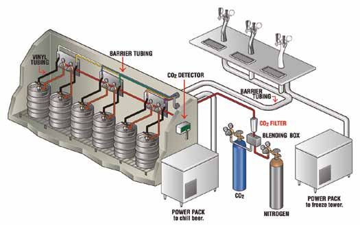
acknowledgements
We would like to thank our industry colleagues whose continued input allowed for the significant updates included
in this edition of this manual. We appreciate their expertise and commitment to consistently deliver the highest
possible quality draught beer to the consumer. If we overlooked anyone who contributed, we sincerely apologize.

Special thanks are extended to Ken Grossman, President of Sierra Nevada Brewing Co. As the 2008 Chair of the
Brewers Association Technical Committee, Ken galvanized the creation of this manual through a collaborative effort
with the brewing community, and we appreciate the time and dedication he and his colleagues put forth to bring
this project to fruition.

Anheuser-Busch InBev: Cian Hickey, Tim Raw
Boulevard Brewing Company: Neil Witte
Brewers Association: Paul Gatza, Charlie Papazian,
Bob Pease, Tim Sloan, Chris Swersey
Cicerone Certification Program: Ray Daniels                                             We are grateful to our industry equipment suppliers
Draught Beer Guild: Martin Schuster                                                     who graciously allowed the use of their graphics and
The Gambrinus Company: Jaime Jurado                                                     equipment information in this manual:
Lucky Bucket Brewing Company: Zac Triemert
MillerCoors: Steve Armstrong, Jeff Ball,                                                Automatic Bar Controls, Inc.
       Ernie Jimenez, Scott Nielsen                                                     Banner Equipment Company
New Belgium Brewing Company: Matt Meadows                                               McDantim, Inc.
Sierra Nevada Brewing Co.: Rob Gerrity,                                                 Micro Matic, Inc.
       Ken Grossman, Laura Harter, Charles Kyle                                         Perlick Corporation

Front cover photo by Michael Lichter Photography.

Special thanks to Avery Brewing Company, Boulder, Colorado. Thanks also to Block 15 Brewing Company, Corvallis,
Oregon and Real Ale Brewing Company, Blanco, Texas for providing images.

The Brewers Association wishes to thank the United States Department of Agriculture and the Colorado State
Department of Agriculture for their support and funding of this project. State funds for this project were matched
with federal funds under the Federal-State Marketing Improvement Program of the Agricultural Marketing Service,
U.S. Department of Agriculture.

SECOND EDITION © Brewers Association, 2011. Chapter heading photos ©2011, Shutterstock, LLC, Jupiter Images, and Getty Images

2                                                                                                                   draught beer quality manual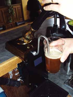
table of contents
     Preface.. . . . . . . . . . . . . . . . . . . . . . . . . . . . . . 1                                       Chapter 4: Equipment and Configurations
     Acknowledgements. . . . . . . . . . . . . . . . . . . . . 2                                               		 for Long-Draw Draught Systems. . . . . . . . . 25

     Introduction. . . . . . . . . . . . . . . . . . . . . . . . . . . 5                                       		 Beer .. . . . . . . . . . . . . . . . . . . . . . . . . . . . . . . . . 25

Section I: Draught Equipment and System                                                                        			 Components. .  .  .  .  .  .  .  .  .  .  .  .  .  .  .  .  .  .  .  .  .  .  .  .  . 26
  Configurations. . . . . . . . . . . . . . . . . . . . . . . . . 6                                            				 Barrier Tubing. .  .  .  .  .  .  .  .  .  .  .  .  .  .  .  .  .  .  .  .  .  . 26
  Chapter 1: Essential Draught System                                                                          				 Choker Line. .  .  .  .  .  .  .  .  .  .  .  .  .  .  .  .  .  .  .  .  .  .  .  . 26
		 Components . . . . . . . . . . . . . . . . . . . . . . . . . .  8                                           				 Wall Brackets. .  .  .  .  .  .  .  .  .  .  .  .  .  .  .  .  .  .  .  .  .  .  . 27
		 Refrigeration/Cooling. .  .  .  .  .  .  .  .  .  .  .  .  .  .  .  .  .  .  .  . 8                         				 FOB (Foam on Beer). .  .  .  .  .  .  .  .  .  .  .  .  .  .  .  .  . 27
		 Keg . . . . . . . . . . . . . . . . . . . . . . . . . . . . . . . . . . . . 9                               				 Beer Pumps. .  .  .  .  .  .  .  .  .  .  .  .  .  .  .  .  .  .  .  .  .  .  .  . 28
		 Keg Valve. .  .  .  .  .  .  .  .  .  .  .  .  .  .  .  .  .  .  .  .  .  .  .  .  .  .  .  .  .  . 9       				 Quick-Connect (or Push) Fittings. .  .  .  .  .  .  . 29
		 Coupler. .  .  .  .  .  .  .  .  .  .  .  .  .  .  .  .  .  .  .  .  .  .  .  .  .  .  .  .  .  .  . 10     		 Gas . . . . . . . . . . . . . . . . . . . . . . . . . . . . . . . . . . . 29
		 Beer Line . .  .  .  .  .  .  .  .  .  .  .  .  .  .  .  .  .  .  .  .  .  .  .  .  .  .  .  .  . 11        				 Carbon Dioxide Gas (CO2). .  .  .  .  .  .  .  .  .  .  .  . 29
		 Faucet. .  .  .  .  .  .  .  .  .  .  .  .  .  .  .  .  .  .  .  .  .  .  .  .  .  .  .  .  .  .  .  . 12   				 Nitrogen Gas (N2). .  .  .  .  .  .  .  .  .  .  .  .  .  .  .  .  .  .  . 30
		 Gas Source. .  .  .  .  .  .  .  .  .  .  .  .  .  .  .  .  .  .  .  .  .  .  .  .  .  .  .  . 14           				 Blended Gas Bottles. .  .  .  .  .  .  .  .  .  .  .  .  .  .  .  .  . 30
		 Gas Line. .  .  .  .  .  .  .  .  .  .  .  .  .  .  .  .  .  .  .  .  .  .  .  .  .  .  .  .  .  . 15		     				 Gas Blenders. .  .  .  .  .  .  .  .  .  .  .  .  .  .  .  .  .  .  .  .  .  .  . 31
		 Regulator . .  .  .  .  .  .  .  .  .  .  .  .  .  .  .  .  .  .  .  .  .  .  .  .  .  .  .  .  . 15        				 Nitrogen Generators . .  .  .  .  .  .  .  .  .  .  .  .  .  .  .  . 31
		 Pressure and Pressure Gauges. .  .  .  .  .  .  .  .  .  .  .  . 16                                         				 Gas Leak Detectors. .  .  .  .  .  .  .  .  .  .  .  .  .  .  .  .  .  . 32
		 A Few Words about Elevation. .  .  .  .  .  .  .  .  .  .  .  .  . 16                                       				 Gas Filters. .  .  .  .  .  .  .  .  .  .  .  .  .  .  .  .  .  .  .  .  .  .  .  .  . 32
		 Tail Pieces and Connectors. .  .  .  .  .  .  .  .  .  .  .  .  .  .  . 17                                  		 Cooling. .  .  .  .  .  .  .  .  .  .  .  .  .  .  .  .  .  .  .  .  .  .  .  .  .  .  .  .  .  .  . 32
		 A Word about Metal Parts & Hygienic Design. . 18                                                            Section II: Draught Operations. . . . . . . . . . . . . . 34
     Chapter 2: Temporary Draught Dispense. . . . 19                                                                Chapter 5: A Matter of Balance. . . . . . . . . . . 35
		 Picnic Pumps . .  .  .  .  .  .  .  .  .  .  .  .  .  .  .  .  .  .  .  .  .  .  .  .  .  . 19              		 Units of Carbonation. .  .  .  .  .  .  .  .  .  .  .  .  .  .  .  .  .  .  .  . 37
		 Jockey Boxes. .  .  .  .  .  .  .  .  .  .  .  .  .  .  .  .  .  .  .  .  .  .  .  .  .  . 20               		 Carbonation Dynamics . .  .  .  .  .  .  .  .  .  .  .  .  .  .  .  .  .  . 37
		 Jockey Box Setup and Use. .  .  .  .  .  .  .  .  .  .  .  .  .  .  . 20                                    		 CO2 Percentage Adjustment. .  .  .  .  .  .  .  .  .  .  .  .  .  . 39
		 Cleaning and Maintenance. .  .  .  .  .  .  .  .  .  .  .  .  .  .  . 20                                    		 Applied Pressure Adjustment. .  .  .  .  .  .  .  .  .  .  .  .  . 39
  Chapter 3: Equipment and Configurations                                                                      		 System Balance . .  .  .  .  .  .  .  .  .  .  .  .  .  .  .  .  .  .  .  .  .  .  .  . 40
		 for Direct Draw Draught Systems. . . . . . . . 22
                                                                                                               		 Designing For Resistance. .  .  .  .  .  .  .  .  .  .  .  .  .  .  .  . 40
		 Drip Tray. .  .  .  .  .  .  .  .  .  .  .  .  .  .  .  .  .  .  .  .  .  .  .  .  .  .  .  .  .  . 23
                                                                                                               		 Mixed Gas . .  .  .  .  .  .  .  .  .  .  .  .  .  .  .  .  .  .  .  .  .  .  .  .  .  .  .  . 40
		 Towers. .  .  .  .  .  .  .  .  .  .  .  .  .  .  .  .  .  .  .  .  .  .  .  .  .  .  .  .  .  .  .  . 23
                                                                                                               		 Dispense Goals . .  .  .  .  .  .  .  .  .  .  .  .  .  .  .  .  .  .  .  .  .  .  .  . 41
		 Shadow Box. .  .  .  .  .  .  .  .  .  .  .  .  .  .  .  .  .  .  .  .  .  .  .  .  .  .  . 24
                                                                                                               		 Balancing Draught Systems . .  .  .  .  .  .  .  .  .  .  .  .  .  . 41
		 Shanks. .  .  .  .  .  .  .  .  .  .  .  .  .  .  .  .  .  .  .  .  .  .  .  .  .  .  .  .  .  .  .  . 24

draught beer quality manual                                                                                                                                                                                           3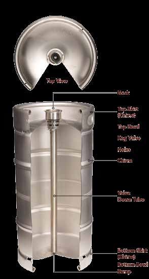
Chapter 6: Preparation to Pour . . . . . . . . . . . 44 Chapter 9: Troubleshooting. . . . . . . . . . . . . . 60
Cold Storage and Proper Chilling of Kegs Off Flavors in Draught Beer . . . . . . . . . . . . . . . 64
before Serving . . . . . . . . . . . . . . . . . . . . . . . . 44 Appendix A: ISBT Guidelines for
Linking Kegs in Series. . . . . . . . . . . . . . . . . . . . 45 Beverage Grade Carbon Dioxide . . . . . . . . 66
Chapter 7: Serving Draught Beer. . . . . . . . . . 46 Appendix B: CO2 Gauge Pressure, Temperature
and Carbonation Level Reference Chart. . . 67
Glassware Cleaning. . . . . . . . . . . . . . . . . . . . . . 46
Appendix C: Carbonation, Blended Gas,
Manual or Hand Cleaning in the
Gas Laws & Partial Pressures. . . . . . . . . . . . 69
Three-Tub Sink . . . . . . . . . . . . . . . . . . . . . . 46
Appendix D: Notes on Serving Cask Ale . . . . 73
Automatic Glass Washing Machines. . . . . . . 47
Appendix E: Tools of the Trade . . . . . . . . . . . 76
Handling Clean Glasses. . . . . . . . . . . . . . . . . 47
Draught Beer Glossary. . . . . . . . . . . . . . . . . . 78
Testing for “Beer-Clean” Glass. . . . . . . . . . . . . 48
Glassware Temperature. . . . . . . . . . . . . . . . . . . 48
Pouring Draught Beer. . . . . . . . . . . . . . . . . . . . 49
Technique. . . . . . . . . . . . . . . . . . . . . . . . . . . . 49
Pouring Hygiene. . . . . . . . . . . . . . . . . . . . . . . 49
Free-Flow Pouring . . . . . . . . . . . . . . . . . . . . . 49
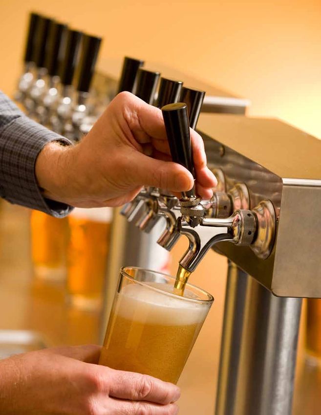
Pouring Growlers. . . . . . . . . . . . . . . . . . . . . . . . 49
Faucet Hygiene. . . . . . . . . . . . . . . . . . . . . . . . 50
Chapter 8: System Maintenance
and Cleaning. . . . . . . . . . . . . . . . . . . . . . . . 51
Cleaning Guidelines . . . . . . . . . . . . . . . . . . . . . 51
Common Issues. . . . . . . . . . . . . . . . . . . . . . . . . 53
Cleaning Safety. . . . . . . . . . . . . . . . . . . . . . . . 53
System Design and Cleanliness. . . . . . . . . . . 53
A Few Words About Mechanical Cleaning. . 53
Other Line Cleaning Methods. . . . . . . . . . . . 54
Line Replacement and Material. . . . . . . . . . . 54
Detailed Recommendations. . . . . . . . . . . . . . . 54
Cleaning Frequency and Tasks . . . . . . . . . . . 54
Cleaning Solutions And Their Usage . . . . . . 54
Caustic-Based Cleaning Chemistry. . . . . . 54
Acid Chemical. . . . . . . . . . . . . . . . . . . . . . . 55
Water Rinsing . . . . . . . . . . . . . . . . . . . . . . . 55
Cleaning Methods and Procedures. . . . . . . . 56
Before You Start . . . . . . . . . . . . . . . . . . . . . 56
Recirculation-Electric Pump Cleaning
Step By-Step Procedure. . . . . . . . . . . . . 56
Static – Pressure Pot Step-By-Step
Procedure . . . . . . . . . . . . . . . . . . . . . . . . 58
Glycol Chiller Maintenance. . . . . . . . . . . . . . . . 58
4 draught beer quality manual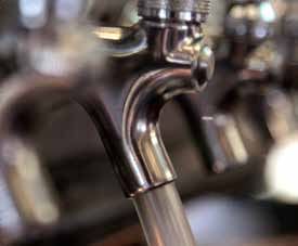
introduction

w           alk into nearly any establishment that
            serves beer these days and you’re
            likely to find draught beer for sale. But
these days you’ll also see fancy options like nitro
beers, highly spritzy German weissbier, and lightly
                                                           While equipment and system layout drive the initial
                                                           performance of a draught system, other factors play an
                                                           equal role in the consumer’s experience. To help you
                                                           understand and operate your draught system, we’ll
                                                           look at the balance equation that can keep perfect beer
carbonated English-style “cask” ales. Glassware            flowing from the taps. We’ll also review pouring and
varies from run-of-the-mill pints to shapely half-liters   glassware cleaning and show you how to check to see if a
and diminutive snifters with every possible shape          glass is “beer clean.” Finally, we’ll focus on the cleaning
and size in between.                                       and maintenance of your draught system. Without
                                                           regular—and proper—maintenance, your investment
We find draught taps so often that we assume it must       in draught technology won’t bring you the dividends
be relatively simple to keep and serve beer this way.      you expect. We’ll conclude this manual by telling you
But behind the simple flick of a handle that sends         what to look for in proper system maintenance, whether
beer streaming into our glass at the bar, you’ll find      doing it yourself or supervising the work of a supplier.
systems that require precise design, exact operating
conditions, and careful, regular maintenance to            To present this information, we have divided this
ensure the proper flow of high-quality beer.               manual into two sections. Section I focuses on
                                                           draught system components and complete system
In this guide, we’ll consider the equipment and            layouts. From a simple party tap to a complex long-
anatomy of draught systems, then look at their             draw draught system, we reviewed all the options.
operation and maintenance. We’ll include a brief
discussion of temporary systems such as picnic             Section II of this manual covers all the operation and
taps and jockey boxes, but the majority of our             maintenance issues for draught systems. It begins
attention will be given to systems usually seen in         with a look at system balance, then progresses to
permanent installations: direct-draw and long-draw         the details of pouring, glass cleaning, and other
draught equipment.                                         essentials of the perfect pint before finishing with
                                                           cleaning and maintenance. n

draught beer quality manual                                                                                           5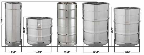
section I

draught equipment and
system configurations

a        mong draught systems, we find three gen-
         eral types based on equipment and design:
         temporary systems, direct-draw systems, and
long-draw systems. In the course of this manual, we’ll
look closely at the layout, operation, and maintenance
                                                         preserve its flavor. In most draught systems, the dis-
                                                         pense gas also propels beer from the keg to the fau-
                                                         cet. Because the dispense gas comes into direct con-
                                                         tact with the beer, it must meet strict criteria for purity.
                                                         And because of the damage it does, compressed air
for each system. In Section I of this manual, we pres-   should never be used to dispense draught beer.
ent four chapters that focus on system components        For the purposes of this manual, as a convention in
from faucets to tubing connectors and see how they       discussions involving mixed gas, the proportion of
are assembled to create different systems. Along the     CO2 will always be shown first, followed by the pro-
way, we’ll review important features of each compo-      portion of N2.
nent that can help prevent operating problems or beer
quality issues in your system.                           Beer
                                                         Most draught systems use the gases mentioned
Before we jump into the components themselves, let’s     above to drive beer from the keg, through tubing
review some key concepts by looking briefly at the       and to the faucet where it will flow into the customer’s
three sub-systems for draught: gas, beer, and cooling.   glass. During the journey from keg to glass, we want
                                                         to protect the beer from anything that would com-
Gas                                                      promise its flavor or alter the carbonation created by
Draught systems use CO2 alone or mixed with nitro-       the brewery. The beer should flow through well main-
gen in varying proportions depending on the require-     tained proper beer lines and avoid any contact with
ments of the system and the beers being served.          brass parts that would impart a metallic flavor. We
When properly selected and set, dispense gas main-       also want the beer to flow at a specific rate and arrive
tains the correct carbonation in the beer and helps to   with the ideal carbonation level. The key to getting

6                                                                              draught beer quality manual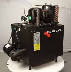
this right is balance between the applied gas pres-
sure and the resistance provided by the tubing and

                                                                temporary systems
fixtures the beer passes through during its journey to
the bar.
                                                                     Picnic Tap
Cooling                                                              Jockey Box
The cooling system should hold beer at a constant
temperature from keg to glass. Any increase in beer             direct draw
temperature between the cooler and the faucet
                                                                     Keg Box
can lead to dispense problems such as foaming. In
                                                                     Walk-in Cooler
a simple direct-draw system, a refrigerated cabinet

                                                                long draw
maintains the temperature of the keg and provides
cooling to the beer as it travels the short distance
to the faucet. Many long-draw systems use a walk-in                  Air-Cooled
refrigerator to cool the kegs, plus chilled glycol that              Glycol-Cooled
circulates in tubes next to the beer lines all the way to            Beer Pump
the faucet, to ensure that the beer stays cold all the               Mixed Gas Dispense

way to the glass.

For each draught dispense system, suitable equip-
ment and designs must be chosen for each of these           the design, setup, use, and maintenance of the two
three components—gas, beer, and cooling. In Section I       main systems: picnic taps and jockey boxes.
of this manual, we’ll examine the equipment used in
draught systems and the various system designs com-         Moving to permanent draught installations, direct-
monly employed.                                             draw systems offer the simplest approach. In Chap-
                                                            ter 3, we’ll talk about the anatomy of a keg box or
Chapter 1 examines nine components common to                “kegerator” and discuss how this basic approach is
nearly all draught systems, such as couplers, faucets,      implemented in a walk-in cooler design. Both here
and beer lines. Understanding these basic elements          and in Chapter 4, we’ll find some new components
will help you operate every draught system you en-          beyond the nine “guidelines” from Chapter 1. In each
counter. Of course, additional components play a role       chapter, we’ll learn about the new components be-
in sophisticated systems—we’ll introduce and discuss        fore looking at the anatomy of the overall system.
those as we encounter them in Chapters 3 and 4.
Once we’ve reviewed the common draught compo-               Permanent installations where the kegs cannot be
nents, we’ll be ready to see how they get used in vari-     located near the serving bar require long-draw
ous system designs.                                         draught systems. Chapter 4 delves into the anatomy
                                                            and operation of air-cooled and glycol-cooled long-
The simplest draught systems serve a temporary              draw systems, and also looks at beer pumps and
need. We find these systems at picnics, beer festivals,     mixed gas dispense solutions to moving beer through
and other short-term events. In Chapter 2, we cover         long-draw dispense systems. n

draught beer quality manual                                                                                      7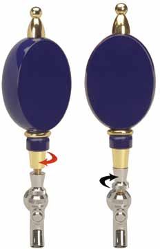
chapter 1

essential draught
system components

a         s a prelude to studying different draught
          system designs, let’s review the equipment
          commonly found in all draught dispense
setups, from the backyard picnic tap to the ballpark
beer vendor. Here we cover nine components:
                                                         benefit the installation by removing the source of heat
                                                         from inside a room or building; however, this requires
                                                         additional refrigerant piping and possibly higher cost.

                                                         Condenser cooling can utilize either air or water;
                                                         both methods have their strengths and weaknesses.
    Refrigeration/Cooling       Gas Source
                                                         In warm climates, air-cooled compressors can lose
    Keg                         Regulator
                                                         significant cooling capacity on a hot day when it is
    Coupler                     Gas Line
                                                         needed most. Water-cooled systems operate more
    Beer Line                   Tail Pieces and
                                                         efficiently, but require more maintenance and invest-
                                  Connectors
    Faucet
                                                         ment cost. Proper preventive care for either system is
                                                         imperative, such as regularly cleaning condenser fins
Refrigeration/Cooling                                    for air-cooled systems, and cooling water treatment
Consistent and controlled beer dispense requires that    for water-cooled equipment to prevent condenser
the beer traveling from keg to glass be maintained at    fouling, which diminishes cooling capacity. Acid
a temperature of 34° to 38°F. While temporary service    cleaning or “roding” out the heat exchanger may be
may employ ice for cooling, most permanent installa-     required to remedy this. Many draught system prob-
tions employ refrigeration systems.                      lems are revealed on the first hot day of the season
                                                         due to a lack of preventive maintenance. Although
Cold box refrigeration systems can provide cooling       R22 refrigerant is still in use, most new installations
for a small direct-draw box cooler or a large walk-in.   will utilize a more environmentally friendly substitute
The refrigeration itself can either be self-contained    such as 404a.
with the compressor and condenser mounted on
the unit or with a remotely mounted compressor and       Glycol systems are also used, as we will see when we
condenser. Remotely mounting the compressor can          examine long-draw systems.

8                                                                            draught beer quality manual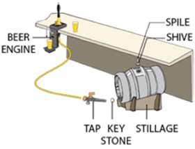
Keg
Kegs enable beer transport and dispense while main-
taining its quality and integrity. Their design protects
beer from both air and light while enabling easy and
rapid dispense. Most brewers use kegs made of stain-
less steel, but you also see rubber-coated, aluminum,
steel—and recently plastic—kegs in the marketplace.
                                                                           Rubber Sided     Bulged Non-Straight Wall
                                                                           1/4 Barrel Keg        1/4 Barrel Keg
When tapped, the keg’s valve admits gas to the head
space where it applies the pressure needed to push
beer up through the spear or down tube and out of
the keg, while maintaining correct carbonation in the
remaining beer.

Keg Valve
Kegs are pressurized vessels and can be dangerous if
mishandled. Nearly all modern kegs use some form of
Sankey valve and stem. There are two main types of San-
key valves and corresponding keg necks: “drop-in,” and
threaded. From a user standpoint, the valves function
identically; from above, they appear nearly indistinguish-
able to the untrained eye. Drop-in Sankey valves are
held in place by a lock ring or circlip. The lock ring and
valve should never be removed in the field. Very rarely a
lock ring can fail, possibly loosening the valve, creating a
potentially dangerous situation. Threaded Sankey valves
screw into the neck of the keg. Very rarely a threaded
valve can inadvertently loosen or become unseated when
disengaging a coupler, creating a potentially dangerous
situation. Keg valves should never be removed in the
field. Kegs should only be serviced by trained personnel.

Older keg designs, although rarely encountered, uti-
lize different tapping methods not covered here. Keg
sizes vary from approximately 5 to 15.5 gallons.

 Sankey Valves and Keg Necks
                                                                                                          Lock Ring
    Threaded                                                   Drop-In

               Keg Neck                                                  Keg Neck
                                      Valve                                                    Valve

draught beer quality manual                                                                                            9
Capacity 1
⁄6 Barrel or Pony Keg ¼ Barrel Full-Size Keg Euro Keg
Cylinder (¼ Barrel) (½ Barrel)
Gallons 5- 5.16 7.75 7.75 15.50 13.2
Ounces 661 992 992 1984 1690
# of 12 oz. beers 55 82 82 165 140
Weight (Full) 58 Pounds 87 Pounds 87 Pounds 161 Pounds 137 pounds
Coupler Couplers include two types of one-way valves:
Gas flows in and beer flows out of a keg through the • Thomas valve – This valve allows CO2 to flow into
coupler. While this device has many casual names the keg but prevents the beer from backing up
in beer cellars around the country, the industry into the gas line if gas pressure drops. This pro-
adopted the term “coupler” as the standard term tects the gas regulators from damage. (Thomas
for the device. valves are removed when kegs are dispensed in
series, see page 45)
When you attach a coupler to a keg to tap it, a probe • Check valve – When the coupler is disconnected
on the bottom depresses a ball or poppet in the keg from the keg, this valve prevents beer from the
valve, allowing CO2 or mixed gas to enter the keg beer line flowing out through the coupler. This
thereby applying pressure to the beer. This forces the prevents beer spillage in keg tapping areas.
beer to travel up the down tube (spear) and drive the
beer to the faucet. A keg coupler should also contain an integral pres-
sure relief valve. If excessive gas pressure were
The coupler is attached to a jumper or a beer line applied to a keg, this valve would open to prevent
using a washer, tail piece, and beer nut. In the US, damage to the keg and coupler. The valve can also be
the threads on beer nuts and couplers are standard opened manually, and this should be done periodi-
sized with the “Cleveland thread,” which is 29/32” cally to test the safety relief valve. The manual release
diameter, and 14 threads per inch pitch. Be aware that usually looks like a small metal pin fitted with a wire
some couplers from other countries may use different ring. To test the valve, pull on the ring to slide the pin
sized threads. Check for leaks after installing a beer a short distance out of the coupler and release a small
nut onto any coupler. amount of gas.
10 draught beer quality manualSankey “D” Twin Probe “S” “A”
“Hoff-Stevens”
“G” “U” “M”
At the time of this writing, most breweries worldwide
The diagram below shows all the features of a coupler use kegs valves compatible with one of six variations
of the Sankey-type coupler (see images above). Most
U.S. breweries use the Sankey “D” coupler, unless oth-
Cut-away of Sankey “D” Coupler
erwise noted. A few U.S. breweries still use the twin
probe Hoff-Stevens valve and coupler system.
Vinyl Barrier
How Coupler Interacts with Keg to Draw Beer
Polyethylene
Beer Line
Between coupler and faucet, beer travels through
beer line selected to fit the needs of the specific
draught application. Options range from vinyl to spe-
cialized barrier tubing and even stainless steel.
Most draught systems use clear vinyl tubing for all or
part of the beer line. In picnic and direct-draw sys-
tems, beer often runs most or the entire route from
coupler to faucet in vinyl tubing. In long-draw sys-
tems, beer commonly passes through two sections of
vinyl hose but travels most of the way in special bar-
rier tubing (See Chapter 4). While vinyl tubing is highly
draught beer quality manual 11flexible, it is best used where lines are not secured in other designs are now becoming widely available
place and where it can easily be replaced. and are used either for their aesthetic appeal or for
serving a specific style of beer. Nitro-Beer faucets are
In later pages, we will encounter other types of tubing used for nitrogenated beers, such as certain stouts.
such as: These faucets use a diaphragm and restrictor plate to
• Colored vinyl and braided vinyl used for CO2 gas “cream” the beer.
• Stainless steel tubing found in jockey boxes and
tap towers In the U.S., all faucets attach to shanks with a stan-
• Barrier tubing; a low-resistance, easy-to-clean dard thread size of 1-1/8” diameter, and 18 threads
beer line for long-draw systems per inch pitch. Be aware that some faucets from other
• Polyethylene tubing used to carry glycol coolant countries may use different thread sizes, and may re-
quire adapters or special shanks. For example, the
Faucet flow control faucet in the chart below is shown with
Faucets dispense beer to the glass. They also hold an adapter to allow it to be used on a standard U.S.
the tap marker to identify the type of beer being shank and tower.
dispensed. The most common faucets are gener-
ally suitable for dispensing both ales and lagers. At retail, most faucets are fitted with tap markers
The most common or “standard” U.S. faucet is that clearly display the brand being dispensed; in
rear-sealing and has vent holes that need to be many states this is required. The tap marker must be
carefully cleaned and inspected during routine clean- aligned properly in order to be read easily by the
ings. Ventless or forward-sealing faucets are easy consumer and sales staff. The tap marker is fitted
to clean and are available in stainless steel. Several with a standard-sized threaded sleeve for easy
Standard European Ventless With Shaft Ventless Without Nitro
Shaft
Spring-Loaded Flow Control Roto-Faucet Speed Nozzle
Cam-Actuated attachment
12 draught beer quality manualPros and Cons of Various Faucet Designs
Type Valve Flow Pro Con
Standard Vertical, seals in back of Smooth Low velocity Barrel interior susceptible to
shaft microbial growth
European Vertical, seals in back of Smooth Low velocity Barrel interior susceptible to
shaft microbial growth; may have
threads that differ from standard
U.S. thread size
Ventless with Vertical, seals in front of Slightly twisting Low susceptibility to High velocity flow may result in
Shaft shaft microbial growth turbulence
Ventless Vertical, seals in front of Slightly twisting Low susceptibility to High velocity flow may result in
without Shaft faucet body microbial growth turbulence
Nitro-Beer Spring loaded cam- Cascade of tiny Gives unique texture Nozzle susceptible to microbial
actuated plunger style bubbles needed for nitro beers growth from beer retained inside
valve. Restrictor plate narrow opening; small nozzle parts
and flow straightener in require manual cleaning; use only
nozzle with nitro beers
Spring-loaded, Horizontal, top of nozzle Slightly twisting Low susceptibility to Nozzle susceptible to microbial
cam-actuated microbial growth growth from beer retained inside
narrow opening; many small parts
to clean
Flow Control Vertical, seals in back of Smooth adjustable Adjustable velocity Barrel interior susceptible to
shaft flow rate may allow for increased microbial growth; may have
dispense pressure threads that differ from standard
U.S. thread size
Roto-faucet Internal, rotating ball Rapid velocity Few parts, simple to Some flow
clean turbulence
Speed-nozzle Attaches to traditional Rapid flow Allows for increased Nozzle immersed in beer,
attachments vented faucet pour rate for high compromising hygiene standards
volume dispense
Faucet Designs - Standard and Ventless
Standard Ventless
1..........Faucet Knob 1..........Faucet Body
2..........Lever Collar 2..........O-Ring
3..........Lever Bonnet 3..........O-Ring Seat
4..........Friction Washer 4..........Coupling Gasket
5..........Ball Washer 5..........Handle Lever
6..........Lever 6..........Bearing Cup
7..........Body 7..........Compression
8..........Coupling Washer Bonnet
9..........Shaft 8..........Handle Jacket
10........Shaft Seat
11........Shaft Nut
12........Faucet Shaft Assembly
draught beer quality manual 13No Air Compressors,
Please!
Systems that use compressed air as a
dispense gas expose beer to oxygen, which
produces stale paper- or cardboard-like
aromas and flavors in the beer. Brewers
go to great lengths to keep oxygen out
of beer to avoid these undesirable stale
characteristics. Air compressors also push
contaminants from the outside atmosphere
into the keg, increasing the chance of beer-
spoiling bacteria and off-flavors. For these
reasons, compressed air should never be
used in direct contact with beer.
installation onto the faucet lever; in many cases, to pressurize a keg as the oxygen in the air gener-
however, the tap marker may not be aligned properly ates stale flavors in beer within just a few hours. All
when seated fully on the lever. For this reason, gas used for beer dispense should meet the speci-
nearly all faucets are also fitted with a lever collar fications of the International Society of Beverage
or handle jacket on the lever (see images above). Technologists or the Compressed Gas Association
These allow the tap marker to be aligned properly, (See Appendix A).
as well as installed securely. Install the tap marker on
the faucet lever and check to make sure it’s aligned Retailers may purchase beverage grade gas in cyl-
appropriately. If not, unscrew the marker just enough inders that will be delivered by the gas vendor and
to align it correctly, then back the lever collar up swapped out when empty. Such cylinders are filled,
under the marker, and tighten the tap marker snugly maintained, and inspected by the vendor. High vol-
onto the lever collar or handle jacket. ume users may purchase a bulk gas vessel known as
a Dewar that will be filled on location from a bulk
Gas Source gas truck. Bulk tanks can provide CO2 for both soda
Draught systems depend on gas pressure to push and beer.
beer from the keg to the faucet. To achieve this, kegs
should be pressurized with carbon dioxide, or a car- CO2 tanks contain both liquid and gas phases. The
bon dioxide and nitrogen mix. tank pressure is dependent on ambient temperature
and—regardless of tank fill level—will vary from 600
Gas used for draught dispense should be “beverage – 1200 psi until empty. For safety reasons, CO2 tanks
grade.” Gas selection and purity affect the freshness should never be located inside the refrigerator or
and quality of the beer served through the draught walk-in cooler. A gas filter may be installed to help
system. Remember: The gas you use fills the keg as reduce the likelihood that any contaminants in the
the beer drains. Thus, off-flavors or impurities in the gas reach the beer (be sure to follow manufacturer
gas quickly migrate to the beer to spoil its freshness recommendations for filter maintenance intervals; see
and flavor. Compressed air should never be used page 32 for more information).
14 draught beer quality manualNote: Breathing high concentrations of CO2
can be deadly! Take care to prevent CO2 buildup
in enclosed spaces such as cold boxes. System leaks
or beer pumps using CO2 can cause this gas to accu-
mulate in the cooler. To prevent this, beer pumps
driven by CO2 must be vented to the atmosphere.
CO2 warning alarms are available and recommended
Primary CO2 Primary Nitrogen
for installations with enclosed areas such as cold Bottle Regulator Bottle Regulator
boxes containing CO2 fittings and gas lines.
Secondary Regulators
Regulator
Braided Vinyl
A regulator adjusts and controls the flow of gas from
any source. Each regulator typically has at least one
Gas Line and often two pressure gauges that help in setting
Gas line should be selected to withstand the pres- pressures and monitoring gas levels. Valves and an
sures expected in the draught system. Vinyl tubing adjustment screw control the actual flow of gas from
is often used as gas line. Vinyl tubing intended to source to destination.
be used as gas line often has a greater wall thick-
ness than vinyl beer line tubing. To help distinguish All gas systems employ a primary regulator attached
between gas line and beer line, colored vinyl is used to the gas source, namely a portable bottle or bulk
for CO2 supply lines in some systems. Clear vinyl tank. This regulator typically contains two gauges:
may also be used as it aids in troubleshooting by one high-pressure showing the tank or supply pres-
allowing you to see if beer has escaped the coupler sure, and a second low- or regulated pressure gauge
and entered the gas line due to a faulty or missing showing what is being delivered to the keg. Some
Thomas valve. And because vinyl gas line will fail simpler regulators may contain only one gauge
at lower pressures than braided vinyl or poly, it can displaying the delivered pressure, making it more
also serve an important safety function in the event difficult to predict when the bottle is getting low on
of secondary regulator failure by blowing off before CO2. Some suppliers provide jockey box regulators
a keg becomes overpressurized. preset with no gauges, since these are easily dam-
aged in transit.
Braided vinyl is often used for CO2, particularly in
high pressure situations (50+ psi) and in long CO2 Regulators are attached to the gas bottle with either
runs. Braided vinyl is commonly used in soft drink an integrated “O” ring seal in the face of the regu-
lines for both beverage and gas. lator fitting, or a fiber or Teflon flat washer. These
parts need to be replaced occasionally to prevent
draught beer quality manual 15leaks and should be inspected every time the bottle of the dispense gas applied to beer beyond the
is changed. Many regulators are also equipped with local atmospheric pressure level. This is called
one or more shut-off valves located on the low-pres- gauge pressure or psig. Gauges in draught beer
sure outlet, allowing the CO2 to be shut off without systems will nearly always read in psig. (Some spe-
changing the set-screw or shutting off the main tank cialized gauges are designed to measure the total
valve. pressure on the beer, or absolute pressure, in units
of psia; these are very rare in draught beer dis-
A primary regulator must also contain a safety relief pense systems.)
valve to prevent dangerous system pressures in case
of a malfunction or frozen regulator. Bottled CO2 As draught beer is dispensed, the carbonation
pressure can exceed 1000 psi, creating an extreme level will depend on the absolute pressure of the
hazard if not handled properly. dispense gas, not the gauge pressure of the dis-
pense gas. This is true for both straight CO2 as well
Nitrogen regulators are designed for higher pres- as blended gas. The carbonation level in a beer is
sures and have a male thread with a conical fitting set by the brewer to maximize flavor, aroma, and pre-
that (depending on the design) seats with or without sentation, and one goal of draught beer dispensing
an O ring. is to maintain this level. If the absolute pressure of
the dispense gas is too high, the carbonation level
Pressure and Pressure Gauges of the beer will increase over time. If the absolute
For the purposes of this manual, pressure is the pressure of the dispense gas is too low, the carbon-
amount of force acting on the surface of beer in a keg ation level of the beer will decrease over time. More
or serving vessel, and is often expressed in pounds information about this very important topic can be
per square inch (psi). Absolute pressure is the total found in Appendix C.
pressure on the beer, and is the sum of atmospheric
pressure plus any additional applied pressure from A Few Words About Elevation
dispense gas. Atmospheric pressure is the amount Because atmospheric pressure changes depending
of force exerted by the weight of air in the Earth’s on elevation, therefore so does the absolute pressure.
atmosphere above an object. At sea level, atmo- So we’ll need to take elevation into account while
spheric pressure is equal to 14.7 psi. If the dispense designing draught beer dispensing systems and when
gas is applied at 15 psi, then the absolute pressure on we read carbonation tables. At higher elevations,
the beer is 29.7 psi (14.7 psi + 15 psi). the layer of air is thinner and therefore weighs less,
so atmospheric pressure is also less. A good rule of
Pressure can be measured several ways. Most pres- thumb is that atmospheric pressure decreases by
sure gauges are designed to measure the pressure about 1 psi per 2,000 feet in elevation.
Elevation Atmospheric Pressure Dispense Pressure Absolute Pressure
(feet above sea level) (PSI) (PSIG) (PSIA)
0 14.7 15 29.7
2,000 13.7 15 28.7
4,000 12.7 15 27.7
5,000 12.2 15 27.2
8,000 10.7 15 25.7
10,000 9.7 15 24.7
16 draught beer quality manualElevation Atmospheric Pressure Dispense Pressure Absolute Pressure
(feet above sea level) (PSI) (PSIG) (PSIA)
0 14.7 15 29.7
2,000 13.7 16 29.7
4,000 12.7 17 29.7
5,000 12.2 17.5 29.7
8,000 10.7 19 29.7
10,000 9.7 20 29.7
Let’s look at an example in which the ideal dispense
gas pressure for a beer brand in a particular draught
beer system at sea level is determined to be 15 psig.
At sea level, atmospheric pressure is equal to 14.7 psi,
so at sea level a keg of beer with dispense gas pressure
of 15 psig is under an absolute pressure of 29.7 psia (15 Step-less hose clamp
psig + 14.7 psi). That same keg of beer at an altitude of
5,000 feet with the same dispense gas pressure of 15
psig is only under 27.2 psia (15 psig +14.7 psi– 2.5 psi).
The chart on page 16 illustrates the absolute pressure
on a keg of beer at different elevations, assuming 15
psig dispense gas pressure. Hex Nut
Even though the gauge pressure on the keg of beer
reads the same, the absolute pressure of the dispense
gas on the keg is decreasing with elevation. Over time,
the carbonation level of the beer being dispensed at Wing Nut
elevation will slowly decrease because the absolute
pressure of the dispense gas is lower than at sea level.
The chart above illustrates that in order to maintain the
carbonation level of beer being dispensed at eleva-
tion, the gauge pressure of the dispense gas needs to
be increased above the calculated dispense pressure Tail Piece
at sea level.
Tail Pieces and Connectors
Tail pieces connect couplers, wall brackets, shanks—or
any other piece of equipment—to vinyl tubing or other Sealing washer
types of beer line. Chromed brass and stainless steel
tail pieces come in several sizes to match common
tubing diameters. They are held in place with a nut and Beer nut and faucet wrench
sealing washer. A clamp secures the tubing to the tail 1 1/32” opening for beer hex nuts
piece on the barbed side. A nut and sealing washer
draught beer quality manual 17attach the tail piece to the coupler or other equipment Manufacturers offer all faucets, shanks, tail pieces,
on its flat side. In the U.S., beer nut and coupler threads splicers, wall brackets, and probes mentioned in this
are one standard size, the so-called “Cleveland thread,” manual in stainless steel. If your system already con-
which is 29/32” diameter with 14 threads per inch. tains chrome-plated brass components, inspect the
beer contact surfaces regularly for exposed brass
A Few Words about Metal Parts and replace those components immediately when
& Hygienic Design this is detected.
For many years, suppliers made metal parts for draught
systems with chrome-plated brass. While chrome has no All system components should be designed to facilitate
negative effect on beer quality, beer that has any contact cleaning and to preclude contamination, particularly
with brass reacts and picks up a metallic off-taste. Exposed due to microbial growth. Indentations, recesses, dead
brass is also difficult to clean. While the chrome coating space, and gaps should be avoided. If dead spaces
on these parts rarely wears away on the outside, cleaning cannot be avoided at the junction between tubing and
and beer flow eventually expose the brass on the inside fittings, their depth should be smaller than the smallest
of these parts, bringing the beer in contact with the brass. dimension of their cross section to facilitate clean-
ing. Edges at protrusions, transitions, and extensions
To avoid brass contact, brewers recommend stainless should be rounded. Components should be designed
steel parts for draught dispense. In addition to being so that they permit an unobstructed flow of liquids and
inert in contact with beer, they are easier to clean and are easy to drain. n
thus help to maintain high quality draught dispense.
18 draught beer quality manualchapter 2
temporary draught
dispense
d raught beer goes great with outdoor
events, but the temporary setting prohibits
use of traditional direct-draw or long-draw
draught equipment. Instead, we usually use one of
two different systems: picnic pumps or jockey boxes.
In the simplest systems, the beer flows to a sim-
ple plastic faucet attached to short section of vinyl
hose. Gas pressure comes from compressed air
introduced by way of a hand-operated pump inte-
grated into the coupler. The pictures at left show
plastic- and metal-construction examples of a
Picnic Pumps picnic tap.
Picnic pumps or party taps allow draught beer
dispense for a one-day occasion or event. These sys- Since these systems introduce compressed air into
tems compromise accepted standards of draught the keg, they are suitable only for situations where
dispense in order to offer a simple method for serving the beer will be consumed in a single day. Also, these
draught beer. dispensing systems typically do not produce the best
serving results, since balancing the correct top pres-
sure is very imprecise. For best results, the keg must
be kept in ice and consistently—but not excessively—
pumped as the contents are dispensed.
Improved designs use single-use CO2 cartridges with
an integrated regulator. These units may also include
a traditional vented faucet mounted on a short length
of stainless steel beer line. This design overcomes the
Plastic Metal with CO2 Cartridge
key shortcomings of hand-pumped picnic taps.
draught beer quality manual 19temperature (64° – 74°F). If the ambient temperature
is above that, the coil-box kegs should be iced as well.
Setup affects the efficiency of both jockey box styles.
To set up a cold plate:
Jockey Boxes • Tap the keg and run beer through the faucet
Jockey boxes offer another way to improve on the before adding ice to the jockey box. This removes
picnic tap as a solution for portable dispense. Here, a water left behind during the cleaning process
normal coupler is attached to the keg and CO2 is used before temperatures in the plate get cold enough
to pressurize the system. Beer in route from keg to to freeze it, causing turbulence or blockage of the
faucet passes through a cold plate or stainless steel beer flow.
tubing inside an ice chest in order to cool it to the • Place ice both underneath and on top of the
proper dispense temperature. A cold-plate-equipped cold plate in the ice chest. As time passes, the ice
jockey box uses ice to cool beer flowing through the will “bridge” and should be removed for better
cold plate. A jockey box equipped with stainless steel contact with the cold plate. Ice should be added
coils uses ice and water to chill beer flowing through periodically and water drained from the ice chest.
the coil. • Set CO2 pressure to 25 to 35 psi. This will vary
depending on how many lines are contained in
These systems are not appropriate for day-to-day the plate and thus how much resistance to flow
use, as draught beer is perishable and room tem- is built into each line. Pressure can be adjusted to
perature storage accelerates that process. They are obtain desired flow rate.
also used with high pressure CO2, which can over-
carbonate a typical keg when tapped longer than a To set up a coil box:
day. Partial kegs remaining from temporary service • Tap the keg and run beer through the coil and out
are not usable in other settings. the faucet.
• Add ice to the ice chest and completely cover
Jockey Box Setup and Use the coil.
Because they have a relatively high surface area for • Add cold water to the top of the coil. This causes
chilling beer, coil-style jockey boxes can pour beer at an ice bath, giving excellent surface contact.
a faster rate than those equipped with a cold plate. • Set CO2 pressure to 35 to 40 psi on 120 ft. coils.
Thus, they better suit situations where faster pour Shorter coils are not recommended, but if used,
rates and volumes are needed. With lower surface should dispense at 30 – 35 psi.
areas for chilling, the cold-plate style is appropriate
when beer dispense needs are a bit slower. Cleaning and Maintenance
Temporary dispense equipment must be cleaned
Kegs used with a cold plate should be iced if the immediately after use. It is nearly impossible to
ambient temperature is above 55°F since they have remove the mold and biofilms that can result from
limited cooling capacity; however, coil boxes can storing a cold plate or jockey box improperly, packed
pour beer efficiently even with the kegs at room with beer.
20 draught beer quality manualFor cleaning jockey boxes, refer to the detailed elec-
tric cleaning pump procedures outlined in Chapter 8.
Afterwards, the water in the lines must be blown out
to prevent mold growth.
• If the recirculation pump is capable of being
run dry:
-- Before breaking down recirculation loop,
remove inlet from rinse water with pump run-
ning so air pushes out all of the rinse water in
the lines.
• If the recirculation pump is not capable of being
run dry:
-- After breaking down the recirculation loop and
reattaching faucets, tap an empty cleaning
canister and use the gas pressure to blow all of
the water out of the lines. n
draught beer quality manual 21chapter 3
equipment and
configurations for direct
draw draught systems
r etailers use direct-draw systems in situations
where the kegs can be kept refrigerated in
very close proximity to the dispense point or
faucet. In some cases, the beer sits in a cooler below
the counter at the bar. In other cases, the keg cooler
• A walk-in cooler with beer dispense directly
through the wall from the keg to the faucet.
The nine components discussed in Chapter 1 appear
in both direct-draw systems; only a little additional
shares a wall with the bar, keeping the beer close to equipment comes into play. As with temporary
the point of dispense. Let’s look at these two types of systems, most direct-draw systems employ vinyl beer
direct-draw systems: line and pure CO2 gas. Compared to barrier tubing,
• A self-contained refrigerator (keg box or “kegera- vinyl beer line is relatively permeable to oxygen
tor”) where the number of kegs accommodated ingress, and the flavor of beer stored in these lines
will vary based on box and keg sizes. can change overnight. As part of their opening
Direct Draw Kegerator Walk-in Cooler
22 draught beer quality manualShort Draw System Direct Draw System
procedures each day, some retailers will dispense
enough beer to repack their vinyl beer lines, and use
the collected beer for cooking.
As permanent installations, direct-draw systems
typically include a drip tray, and some systems also
incorporate a tap tower. In addition, shanks support Two-Faucet Tower Eight-Faucet Pass-Thru
the faucets in either tower or wall-mount applica- (forced-air or glycol) (forced-air or glycol)
tions. The following sections discuss these elements
of the system. Towers
Direct-draw keg boxes and most long-draw systems
mount the dispensing faucet on a tower. This tower
attaches to the top of the bar or keg box. Towers
come in various shapes and sizes and may have any-
where from one to dozens of faucets.
To achieve proper beer service, the beer line running
through the tower to the faucet must be kept at the
Surface Mount Drip Tray Wall Mount Drip Tray
same temperature as the beer cooler. Direct-draw sys-
tems use air cooling, while long-draw systems usually
Drip Tray use glycol cooling. The air-cooled towers are insulated
Many draught systems include a drip tray placed below on the inside and cold air from the cooler circulates
the faucets and most health departments require them. around the beer lines and shanks. This works with direct-
draw systems thanks to the close proximity of the tower
Many walk-in based direct-draw systems use a wall- to the cold box. Some keg boxes have specialized corru-
mounted drip tray that includes a back splash. This gated tubing connected to the refrigerator’s evaporator
design may be used on some air-cooled long-draw sys- housing. This tubing is designed to be inserted in the
tems as well. Bars typically place surface or recessed tower to provide for cold air flow up to the faucet. Typi-
drip trays under draught towers. The drip trays should cally cold air is supplied directly from the discharge of
be plumbed to drain into a drain or floor sink. the evaporator and is colder than the keg temperature.
draught beer quality manual 23Bent Tube Shank Nipple Shank
Shanks
Most draught systems firmly mount the faucet to
either a tower or a wall, making it a stable point for
beer dispense. A threaded shank with securing nuts
creates the solid connection to the supporting tower
or wall. The faucet then connects to one side of the
shank and beer line connects to the other side by
either an attached nipple or a tail piece connected
with the usual washer and nut. Today, shanks with
1/4” and 5/16” bore diameters are most commonly
available and recommended in the U.S., along with
3/16” bore diameter shanks, which are less common.
The once-common practice of drilling out a 3/16”
Shadow Box bore diameter shank to one of the larger sizes is
In some direct-draw applications inside a walk-in not recommended as the resulting unfinished brass
cooler, it may be necessary to cut a section out of shank bore surface will be detrimental to draught
the cooler wall where the shanks are placed. The wall beer quality, and because drilling will likely dam-
is then recessed in a “shadow box” to minimize the age shanks and glycol chilled towers beyond repair,
shank length and keep foaming to a minimum. meaning expensive replacement will be necessary. n
24 draught beer quality manualchapter 4
equipment and
configurations for
long-draw draught
systems
t he most complex draught systems fall into the long-
draw category. Designed to deliver beer to bars
well away from the keg cooler, these systems usually
employ equipment not seen in temporary and direct-draw
setups. From around 1990 to 2010, the average long draw
Beer
While exceptions exist, most long-draw systems still
push beer from kegs. Beer exits the keg through a
coupler and usually enters a vinyl beer line just as we
have seen with temporary and direct-draw systems.
system had doubled in complexity from roughly five fau- But here the vinyl doesn’t last long. It typically goes
cets to more than 10 faucets. Today it’s not uncommon to about six feet before connecting to a wall bracket
find very complex draught beer systems at retail with doz- that serves as a transition to specialized barrier tub-
ens of faucets, dispensing up to many dozens of beer ing. Designed for minimum resistance and superior
brands. While long-draw systems offer designers the cleanliness, barrier tubing should carry beer most of
option to put beer far from the bar, providing keg handling the distance from keg to faucet in long-draw systems.
or layout flexibility, the distances they cover come with But barrier tubing isn’t the end of the journey; most
increased opportunities for problems and increased costs draught towers use stainless steel tubing to carry the
for equipment, cooling, and beer waste. As with all systems, beer to the faucet. In addition, many systems install
it’s important to minimize line length and diameter where some length of narrow-gauge vinyl tubing called
possible to minimize beer loss and facilitate cleaning. “choker” between the end of the barrier tubing and
the stainless steel tubing of the draught tower, to pro-
Let’s consider the three draught dispense sub-systems vide a way to accurately balance the system. In the
of beer, gas, and cooling to see what long-draw systems end, however, the beer flows through a faucet just as
include. we saw with the direct-draw systems.
draught beer quality manual 25Long-Draw System
You may also find Foam On Beer (FOB) detectors on Many older long-draw systems installed single-wall
the beer lines of many long-draw systems. Located in polyethylene tubing. This relatively porous material
the cooler at or near the wall bracket, these devices allows oxygen ingress, carbon dioxide to escape, and
fill with dispense gas when beer from a keg runs out, makes cleaning difficult, resulting in stale, flat, and
thereby shutting off flow to the main beer line. This potentially tainted beer in the lines. Today, you may
prevents beer loss by keeping the main beer line full find blue and red polyethylene tubing carrying glycol
of pressurized beer while the keg is changed. The from and to your glycol power pack; this is the only rec-
jumper line between the keg and FOB is then purged ommended use for polyethylene tubing in long-draw
and normal beer service can resume. See page 27 for systems. Long-draw systems with vinyl or poly lines
more information about FOBs. (typical of much older systems) should be repacked
with fresh beer each day due to the detrimental effects
Components: of oxidation; the beer drained during this process can
be used for cooking. This expense alone can signifi-
Barrier Tubing cantly decrease the payback time when replacing an
Barrier tubing has a “glass-smooth” lining that inhibits old long-draw system with barrier tubing.
beer or mineral stone deposits and microbial growth to
maintain beer freshness. Its properties make it the only Vinyl tubing should only be used as jumpers between
industry-approved beer line for long-draw systems. keg couplers and long-draw barrier tubing trunks,
and as restriction tubing between barrier tubing
Barrier tubing may be purchased by itself in various trunks and faucet shanks. Vinyl and polyethylene
diameters, but most suppliers sell it in prepared bun- tubing should never be used in long-draw bundles.
dles (called bundle or trunk housing) with beer lines
and glycol coolant lines wrapped inside an insulating Choker Line
cover. These bundles vary by the number of beer lines Choker line, also known as restriction tubing, is a sec-
they carry with popular sizes matching the number of tion of 3/16” ID vinyl tubing of variable length installed
faucets commonly found on tap towers. at the tower end of a long-draw system. The purpose is
26 draught beer quality manualto add to the overall system restriction and thus achieve
the target flow rate at the faucet. It is connected at one
end to the barrier tubing in the trunk housing with a
reducing splicer, and at the other to a hose barb on
either the back side of the shank inside the tower, or to
the stainless tubing extending from the tower.
A few different specially designed devices can be Stainless
Plastic FOB Plastic FOB
Steel FOB
used as alternatives to constructing final choker
restriction with long lengths of 3/16” ID polyvinyl
hose. One such device is a series of plastic segments FOB (Foam On Beer)
that are inserted into a short section of 1/4” ID barrier FOBs stop the flow of beer through a line once the
tubing just below the tower; another is a wire mesh keg empties. This reduces the beer loss normally
device installed in the shank just behind the faucet. associated with changing a keg and therefore reduces
These devices are of varying restriction and, while operating costs. While available in different designs,
potentially useful, also have some potential down- most feature a float in a sealed bowl that drops when
side. For one, these items prevent beer line cleaning beer flow from the keg stops. The FOB allows the
with sponges as an option. Additionally, the increased beer lines to stay packed. This makes for less prod-
surface area may increase the likelihood of bacterial uct loss and generates savings for the account. FOBs
buildup or foaming. should be cleaned every two weeks when the draught
system is cleaned and completely disassembled and
manually cleaned quarterly to assure a clean system.
One-Faucet Wall Bracket Two-Faucet Wall Bracket
Wall Brackets
Wall brackets join tubing together in a long-draw cold
box. The wall bracket gives a solid connecting spot Another version of an FOB that performs the same
for jumper lines from the keg. Tubing is connected function is available as an existing feature on a keg
with a washer, nut, tail piece, and clamp combina- coupler, as shown above. This variety does not have
tion. (Most of these installed in the past were made of a float but smaller moving parts that shut off the flow
plated brass, and should be inspected for wear and of beer when gas is present. It is not as easily dis-
replaced with stainless steel.) assembled or cleaned as the wall-mounted varieties
draught beer quality manual 27You can also read