Dual-Band Monopole Antenna for RFID Applications - MDPI
←
→
Page content transcription
If your browser does not render page correctly, please read the page content below
future internet

Article
Dual-Band Monopole Antenna for RFID Applications
Naser Ojaroudi Parchin 1, * , Haleh Jahanbakhsh Basherlou 2 , Raed A. Abd-Alhameed 1                      and
James M. Noras 1
 1    Faculty of Engineering and Informatics, School of Electrical Engineering and Computer Science,
      University of Bradford, Bradford BD7 1DP, UK; r.a.a.abd@bradford.ac.uk (R.A.A.-A.);
      j.m.noras@bradford.ac.uk (J.M.N.)
 2    Microwave Technology Company, Ardabil 56158-46984, Iran; Hale.Jahanbakhsh@gmail.com
 *    Correspondence: n.ojaroudiparchin@bradford.ac.uk; Tel.: +44-7341436156

 Received: 30 December 2018; Accepted: 26 January 2019; Published: 30 January 2019

 Abstract: Over the past decade, radio-frequency identification (RFID) technology has attracted
 significant attention and become very popular in different applications, such as identification,
 management, and monitoring. In this study, a dual-band microstrip-fed monopole antenna has
 been introduced for RFID applications. The antenna is designed to work at the frequency ranges of
 2.2–2.6 GHz and 5.3–6.8 GHz, covering 2.4/5.8 GHz RFID operation bands. The antenna structure
 is like a modified F-shaped radiator. It is printed on an FR-4 dielectric with an overall size of
 38 × 45 × 1.6 mm3 . Fundamental characteristics of the antenna in terms of return loss, Smith Chart,
 phase, radiation pattern, and antenna gain are investigated and good results are obtained. Simulations
 have been carried out using computer simulation technology (CST) software. A prototype of the
 antenna was fabricated and its characteristics were measured. The measured results show good
 agreement with simulations. The structure of the antenna is planar, simple to design and fabricate,
 easy to integrate with RF circuit, and suitable for use in RFID systems.

 Keywords: dual-band antenna; microstrip-fed printed antenna; monopole antenna; RFID;
 wireless communication

1. Introduction
     RFID is a recent outstanding technology which uses radio frequency (RF) signals for the
identification of objects and has been employed in many applications, such as service industries
and moving vehicle identification [1]. In general, RFID is a paste and tag antenna for the purpose of
identification and tracking by radio. An RFID system contains three major components: a transponder,
a reader, and a computer for data processing. The reader (Interrogator) includes an antenna, which
communicates with the TAG [2]. The antenna should be inexpensive, light, simple, and easy to
fabricate [3].
     Different frequency bands of the electromagnetic spectrum, such as 130 kHz (low-frequency),
13.5 MHz (high-frequency), 900 MHz (ultra-high-frequency), 2.4 GHz, 5.8 GHz, and 24 GHz
(microwave frequency) are allocated for RFID applications [4]. Recently, several antenna designs with
single, dual, and multi-band characteristics were reported in the literature for RFID applications [5–8].
A closely-spaced loop antenna array with directional radiation patterns is proposed in [5] to operate
at 900 MHz. In [6], an active RFID tag antenna operating at 2.4 GHz has been introduced for RFID
applications. In [7], a dual-band circularly-polarized antenna is designed for covering both 900 MHz
and 2.4 GHz frequency bands. Another design with multi-band function is proposed in [8], which can
cover 0.9/2.4/5.8 GHz RFID frequency bands. In this study, 2.4 GHz and 5.8 GHz are selected as the
desired dual operation bands for RFID applications [9–12].

Future Internet 2019, 11, 31; doi:10.3390/fi11020031                       www.mdpi.com/journal/futureinternet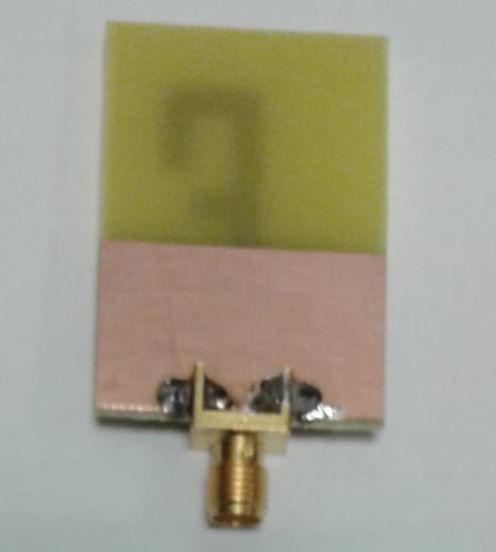
Future Internet 2019, 11, 31 2 of 10
Printed monopole antennas are very attractive and suitable for dual-band or multi-band
applications owing to their simple structures, compact size, good impedance matching,
Future Internet 2019, 11, x FOR PEER REVIEW 2 of 10
and omnidirectional radiation patterns [13]. Multi-band monopole antennas can be realized by
employing parasitic
Printed structures,
monopole slots,are
antennas or slits
very in the antenna
attractive and configuration or usingor
suitable for dual-band various radiating
multi-band
elements with different shapes [14]. Configuration of the presented design
applications owing to their simple structures, compact size, good impedance matching, and consists of a modified
F-shaped radiation patch,
omnidirectional radiationa rectangular
patterns [13].microstrip
Multi-bandfeed-line,
monopoleand a ground
antennas can beplane. The
realized by antenna
employing with a
planarparasitic
structurestructures,
is designedslots,on
or an
slitsFR-4
in the antenna configuration
substrate. Its frequencyor using various
operation covers radiating elementsbands
the frequency
from with different
2.2–2.6 GHz and shapesfrom[14]. Configuration
5.3–6.8 GHz. The of antenna
the presented design
provides consists of a modified
omnidirectional radiationF-shaped
patterns at
radiation patch, a rectangular microstrip
both of the desired frequency bands (2.4 and 5.8 GHz). feed-line, and a ground plane. The antenna with a planar
structure is designed on an FR-4 substrate. Its frequency operation covers the frequency bands from
In contrast to the reported RFID antenna designs [5–12], the presented design exhibits wider
2.2–2.6 GHz and from 5.3–6.8 GHz. The antenna provides omnidirectional radiation patterns at both
impedance bandwidth at lower and upper operation bands with higher gain values, especially at the
of the desired frequency bands (2.4 and 5.8 GHz).
upper band. The antenna
In contrast to the operation
reported RFID bandwidth
antenna is highly[5–12],
designs sensitive to small changes
the presented in the fabrication
design exhibits wider
process.
impedance bandwidth at lower and upper operation bands with higher gain values, especiallytoatlower
There must be very strict guidelines in order to avoid shifting of the resonance the or
higher frequencies
upper band. The outside
antennathe required
operation narrow band
bandwidth of interest.
is highly sensitive This drawback
to small changescould be avoided if a
in the fabrication
wideband
process.antenna is designed
There must be veryinstead [15]. Theinproposed
strict guidelines RFIDshifting
order to avoid antennaofprovides moretothan
the resonance lower85%or total
higher frequencies outside the required narrow band
efficiency characteristic at the resonant frequencies (2.4/5.8 GHz). of interest. This drawback could be avoided if
a wideband antenna is designed instead [15]. The proposed RFID antenna provides more than 85%
total efficiency
2. Antenna Designcharacteristic at the resonant frequencies (2.4/5.8 GHz).
and Configuration
Configuration
2. Antenna Designof theandantenna is illustrated in Figure 1. It is printed on a low-cost FR-4 dielectric,
Configuration
whose relative permittivity, loss tangent, and thickness are 4.4, 0.025, and hsub = 1.6 mm, respectively.
Configuration of the antenna is illustrated in Figure 1. It is printed on a low-cost FR-4 dielectric,
The FR4 dielectric combines good electrical features, price, and availability. Compared with other
whose relative permittivity, loss tangent, and thickness are 4.4, 0.025, and hsub = 1.6 mm, respectively.
materials,
The FR4FR4 material
dielectric is sufficiently
combines cheap and
good electrical available
features, price, in the
and market and
availability. has been
Compared widely
with other used
in antenna designing
materials, for frequencies
FR4 material is sufficientlyless than
cheap and6 available
GHz. Moreover, FR-4and
in the market material iswidely
has been available
usedininmore
thickness values than other ones, which gives more design flexibility. However,
antenna designing for frequencies less than 6 GHz. Moreover, FR-4 material is available in more as the antenna
operation frequency
thickness values isthan
increased, the permittivity
other ones, which gives of FR-4design
more variesflexibility.
and loss in the substrate
However, as theincreases
antenna [16].
operation
Therefore, frequency isfrequency
for ultra-high increased, designs,
the permittivity of FR-4
it is better varies
to use and loss prone
materials in the substrate increases
to loss, such as Arlon,
[16].
Roger, andTherefore,
others. for ultra-high frequency designs, it is better to use materials prone to loss, such as
Arlon, Roger, and others.
Figure 1. (a) Side, (b) top, and (c) bottom views of the antenna.
Figure 1. (a) Side, (b) top, and (c) bottom views of the antenna.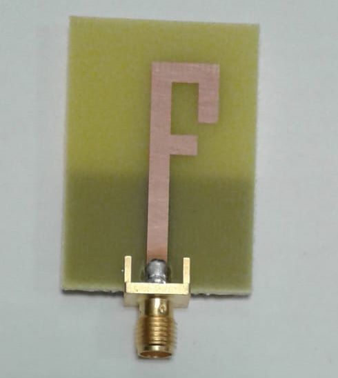
Future
Future Internet
Internet 2019,
2019, 11,
11, x31FOR PEER REVIEW 33 of
of 10
10
Future Internet 2019, 11, x FOR PEER REVIEW 3 of 10
The radiation patch of the designed antenna is connected to a rectangular feed-line with Wf
The radiation patch of the designed antenna is connected to a rectangular feed-line with Wf
widthThe
andradiation patch
Lf length. Theof the designed
width antenna isfeed-line
of the microstrip connected to a rectangular
is fixed at 3 mm. Onfeed-line withside
the other Wf of
width
the
width and Lf length. The width of the microstrip feed-line is fixed at 3 mm. On the other side of the
and Lf length.
substrate, The width of
a conducting the microstrip
ground plane offeed-line is fixed
Wsub width andat 3Lgnd
mm. On theisother
length sideThe
placed. of the substrate,
antenna is
substrate, a conducting ground plane of Wsub width and Lgnd length is placed. The antenna is
a conducting
connected to aground planeconnector
50 Ω SMA of Wsub width and transmission.
for signal Lgnd length is Theplaced. The antenna
parameter valuesisfor
connected to a
the antenna
connected to a 50 Ω SMA connector for signal transmission. The parameter values for the antenna
50 Ω SMA
design connector
are listed for signal
in Table 1. transmission. The parameter values for the antenna design are listed
design are listed in Table 1.
in Table 1.
Table 1. Parameter values of the antenna design.
Table 1.
Table 1. Parameter
Parameter values
values of
of the
the antenna
antenna design.
design.
Parameter Value (mm) Parameter Value (mm) Parameter Value (mm)
Parameter
Parameter Value(mm)
Value (mm) Parameter
Parameter Value
Value (mm) Parameter Value (mm)
WSub 28 Lsub 40(mm) Parameter
hsub Value
1.6 (mm)
WW
WSub 28
28 L
LL
sub 40
40
h sub
hsub
1.6
Subf 3 f
sub 20 W 101.6
W Wf 343 LLf f 20
20 WW 10
Wf 1 W2 4 L 810
WW 1 44 W2
W 4 LL 88
L11 6 L22 3 L3 3
L1L1 66 LL22 33 LL33 33
LL4 4 33 LLgnd
gnd 17
17 WW3 3 33
L4 3 Lgnd 17 W3 3
3. Results and Discussions
3.
3. Results
Results and
and Discussions
Discussions
The motive behind the presented design is to achieve a dual-band characteristic for use in RFID
The
The motive
motive behind
behind the
the presented
presented design
design is
is to
to achieve
achieve aa dual-band
dual-band characteristic
characteristic for
for use
use in
in RFID
RFID
applications. This has been achieved by using the presented antenna design with a modified radiation
applications.
applications. This
This has
has been
been achieved
achieved byby using
using the
the presented
presented antenna
antenna design
design with
with aa modified
modified radiation
radiation
patch. Return loss characteristics of the rectangular monopole antenna (Figure 2a), the antenna with
patch.
patch. Return
Return loss
losscharacteristics
characteristicsof
ofthe
therectangular
rectangularmonopole
monopoleantenna
antenna(Figure
(Figure2a),
2a),the antenna
the antenna with a
with
a Γ-shaped radiating patch (Figure 2b), and the antenna with a modified F-shaped radiator (Figure
Γ-shaped
a Γ-shaped radiating patch
radiating patch(Figure 2b),
(Figure and
2b), thethe
and antenna with
antenna a modified
with F-shaped
a modified F-shapedradiator (Figure
radiator 2c)
(Figure
2c) are illustrated compared in Figure 3.
are illustrated compared in Figure 3.
2c) are illustrated compared in Figure 3.
(a) (b) (c)
(a) (b) (c)
Figure 2. Different structures of the antenna, (a) rectangular-shaped, (b) Γ-shaped, and (c) F-shaped.
the antenna,
Figure 2. Different structures of the antenna, (a)
(a) rectangular-shaped, (b) Γ-shaped,
rectangular-shaped, (b) Γ-shaped, and
and (c)
(c)F-shaped.
F-shaped.
Figure 3. The return losses for the structures shown in Figure 2.
Figure 3. The return losses for the structures shown in Figure 2.
Figure 3. The return losses for the structures shown in Figure 2.Future Internet 2019, 11, 31 4 of 10
Future
Future Internet
Internet 2019,
2019, 11,
11, xx FOR
FOR PEER
PEER REVIEW
REVIEW 44 of
of 10
10
It is observed that the lower frequency bandwidth (2.2–2.6 GHz) with a resonance at 2.6 GHz
is affected by Γ-shaped
It is observed that thestructure, and the upper-frequency
lower frequency bandwidth (2.2–2.6 bandwidth
GHz) with (5.2–6.8 GHz), at
a resonance resonating
2.6 GHz is at
5.8 GHz,by
affected is Γ-shaped
created and improved
structure, andby theadding a short rectangular
upper-frequency bandwidth strip, whichGHz),
(5.2–6.8 modifies the radiation
resonating at 5.8
GHz, is created and improved by adding a short rectangular strip, which modifies the radiation patch ,
patch to the F-shaped structure. The optimized length L resonance is set to resonate around 0.25λ resonance
where
to Lresonance1
the F-shaped = L3 + The
structure. L2 +optimized
L + L4 +length (W −LW 3 ) +L
resonance
resonance
andto Lresonate
is1 set = L3 +0.25λ
resonance2around W2 resonance
+ Wf /2
resonance
+ L2 .
, where
Lλresonance1
resonance1
resonance1 = Land + L + L44 correspond
λ22resonance2
33 + L + (W − W33) +L to 11the
andfirst and second resonance frequencies
Lresonance2
resonance2 = L33 + W22 + Wff/2 + L22. λresonance1
(2.4 GHz
resonance1 and λresonance2
and
resonance2
5.8 GHz), respectively.
correspond to the first and second resonance frequencies (2.4 GHz and 5.8 GHz), respectively.
Thevoltage
The voltagestanding
standingwave waveratio
ratio(VSWR)
(VSWR)and andSmith-Chart
Smith-Chartresultsresultsof ofthe
theantenna
antennaare arerepresented
represented
in Figure 4. It is seen that the antenna properly resonates
in Figure 4. It is seen that the antenna properly resonates at 2.4 and 5.8 GHz. As shown, it at 2.4 and 5.8 GHz. Asoperates
shown,
it operates from 2.2 to 2.6 GHz (400 MHz impedance-bandwidth)
from 2.2 to 2.6 GHz (400 MHz impedance-bandwidth) and from 5.3 to 6.8 GHz (1500 MHz and from 5.3 to 6.8 GHz (1500 MHz
impedance-bandwidth). In
impedance-bandwidth). Inaddition,
addition,thethereflected
reflected phase
phase of of the
the antenna
antenna SS11 andits
11and
11 itsreal
realand
andimaginary
imaginary
parts are illustrated in Figure 5, respectively. As seen, the effects of the resonances
parts are illustrated in Figure 5, respectively. As seen, the effects of the resonances at 2.4/5.8 GHz at 2.4/5.8 GHzare are
evident in the provided
evident in the provided results. results.
(a) (b)
Figure
Figure4.4.(a)
(a)VSWR
VSWRand
and(b)
(b)Smith-Chart
Smith-Chartresult
resultof
ofthe
theantenna.
antenna.
(a) (b)
(a)Phase,
Figure5.5.(a)
Figure Phase,(b)
(b)real
realand
andimaginary
imaginaryparts
partsof
ofthe
theantenna.
antenna.
Inorder
In order to
to further
further understand
understand the the principle
principle of
of the
the dual-band
dual-band characteristic,
characteristic, simulated
simulated surface
surface
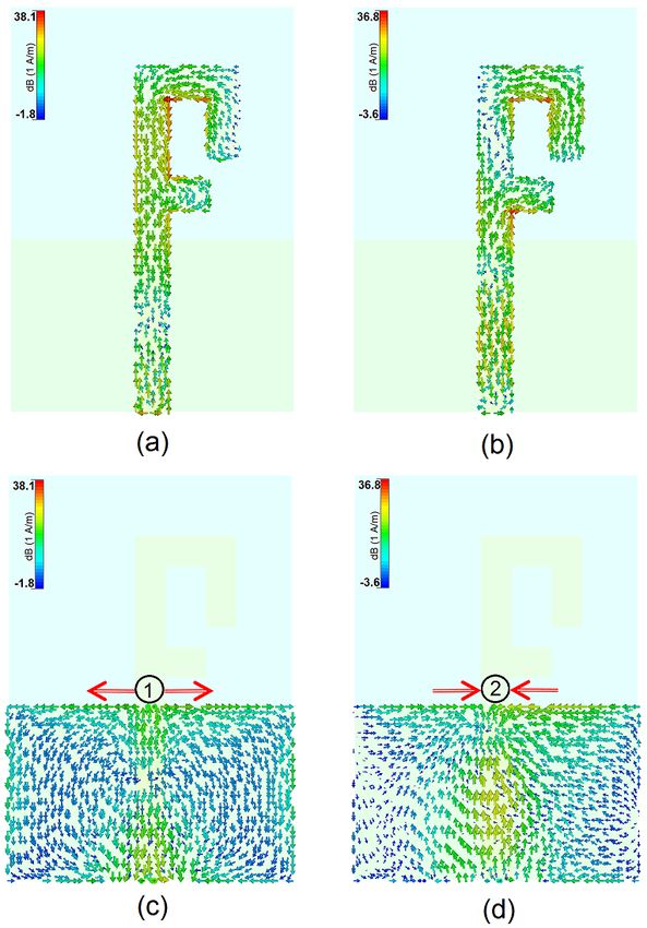
current densities for the resonant frequencies on the radiation patch and the ground
current densities for the resonant frequencies on the radiation patch and the ground plane areplane are illustrated
in Figure 6.inAs
illustrated seen in
Figure 6. Figure
As seen6a,inatFigure
2.4 GHz,
6a,the current
at 2.4 GHz, flow
thecontraries on the
current flow interior edge
contraries on theofinterior
the first
edge of the first resonator (the main arm of the modified F-shaped radiation patch). At 5.8 GHz, the
current flows are highly dominated around the second arm of the radiation patch, as illustrated in
Figure 6b. Figure 6c,d show the current distributions in the ground plane of the proposed design atFuture Internet 2019, 11, 31 5 of 10
resonator (the main arm of the modified F-shaped radiation patch). At 5.8 GHz, the current flows are
highly dominated around the second arm of the radiation patch, as illustrated in Figure 6b. Figure 6c,d
Future Internet 2019, 11, x FOR PEER REVIEW 5 of 10
show the current distributions in the ground plane of the proposed design at the resonant frequencies:
the currenttheflow concentrates
resonant frequencies:around the topflow
the current edgeconcentrates
of the ground plane.
around theIn
topaddition, it isground
edge of the observed thatIn
plane.
at 5.8 GHz,addition, it is observed that at 5.8 GHz, the direction of current flows changes at the edges of to
the direction of current flows changes at the edges of the ground plane in comparison the
that at theground
first resonance (2.4 GHz).to that at the first resonance (2.4 GHz).
plane in comparison
Figure 6. Current distributions at (a) 2.4 GHz and (b) 5.8 GHz on the radiation patch, and (c) 2.4 GHz
Figure 6. Current distributions at (a) 2.4 GHz and (b) 5.8 GHz on the radiation patch, and (c) 2.4 GHz
and (d) 5.8and
GHz in the ground plane.
(d) 5.8 GHz in the ground plane.
Results ofResults
varying fundamental
of varying design design
fundamental parameters, W1 , WW
parameters, 2 ,1,L,
WL2,1L,
, LL2 ,1,LL32,, LL43,, Land L Lgndare
4, andgnd areshown
shown
in Figurein7a–h. Figure 7a,b shows the effects of L and
Figure 7a–h. Figure 7a,b shows the effects of L and L 2 on the impedance matching;
L2 on the impedance matching; the operation the operation
frequency bands ofbands
frequency the antenna are not
of the antenna areaffected significantly.
not affected significantly.InIncontrast,
contrast, as shownininFigure
as shown Figure 7c,d,
7c,d, the
the returnreturn
loss characteristic of the
loss characteristic ofantenna can can
the antenna be tuned at both
be tuned of the
at both resonant
of the resonant frequencies
frequenciesfor fordifferent
different
values of values
L1 andofWL11.and
Figure
W1. 7e,f illustrates
Figure the impact
7e,f illustrates of different
the impact values
of different for Lfor
values 3 andL3 and W2Won the
2 on theantenna
antenna
operation frequency; they have significant impacts on the second resonant
operation frequency; they have significant impacts on the second resonant frequency (5.8 GHz) with frequency (5.8 GHz) with
very little impact on the first resonant frequency (2.4 GHz). It is observed from Figure 7g,h that theFuture Internet 2019, 11, 31 6 of 10
veryFuture
littleInternet
impact 2019,
on 11,the
x FOR PEER
first REVIEW frequency (2.4 GHz). It is observed from Figure 7g,h6 that
resonant of 10 the
isolation and impedance-matching characteristics of the antenna at both resonant frequencies are
isolation and impedance-matching characteristics of the antenna at both resonant frequencies are
highly depended on values of Lgnd and L4 . Figure 8 illustrates the antenna fundamental radiation
highly depended on values of Lgnd and L4. Figure 8 illustrates the antenna fundamental radiation
characteristics over the operation bands. As shown, more than 75% radiation and total efficiencies
characteristics over the operation bands. As shown, more than 75% radiation and total efficiencies
(R.E.(R.E.
andand T.E.) have
T.E.) havebeenbeenachieved
achievedatatthe
thefrequency
frequency bands. Morethan
bands. More than2 2dBi
dBi and
and 4 dBi
4 dBi maximum
maximum gaingain
levels are are
levels obtained
obtained forfor
thethe
antenna
antennaatat2.4
2.4and
and5.8
5.8 GHz, respectively.
GHz, respectively.
(a) (b)
(c) (d)
(e) (f)
(g) (h)
Figure
Figure 7. Return
7. Return lossloss results
results forfor differentvalues
different valuesof
of(a)
(a) L,
L, (b)
(b) L
L22,, (c)
(c) W
W11, ,(d)
(d)LL
1, 1(e) L3L
, (e) , (f) W2W
3 , (f) , (g) LgndL, gnd ,
2 , (g)
and and
(h) L(h)
4 . L 4.Future Internet 2019, 11, 31 7 of 10
Future
Future Internet
Internet 2019,
2019, 11,
11, xx FOR
FOR PEER
PEER REVIEW
REVIEW 77 of
of 10
10
Figure 8.
Figure The antenna
8. The antenna fundamental
fundamental radiation
radiation characteristics.
characteristics.
Top and
Top and bottom
bottom views
views for
for the
the prototype
prototype are
are illustrated
illustrated inin Figure
Figure 9. The antenna
9. The antenna hashas been
been
××28 3
constructedon
constructed onaalow-cost
low-costFR4FR4dielectric
dielectricsubstrate
substratewith
with anan overall
overall dimension
dimension of of
40 40
× 28 1.6×mm
1.6 3mm
3 . The .
The measured
measured and simulated
and simulated return
return loss characteristics
loss characteristics of the ofantenna
the antenna are represented
are represented in Figure
in Figure 10. As10.
As can be observed, the antenna exhibits good return loss characteristic, covering 2.4/5.8
can be observed, the antenna exhibits good return loss characteristic, covering 2.4/5.8 GHz resonant GHz resonant
frequencies, which
frequencies, which compared
compared with
with the
the simulated
simulated result,
result, the
the agreement
agreement isis acceptable.
acceptable. However,
However, therethere
is a slight discrepancy between them which could be mostly due to possible errors
is a slight discrepancy between them which could be mostly due to possible errors in the prototypein the prototype
dimensions as
dimensions as well
well as
as the
the permittivity
permittivity ofof the
the high-loss
high-loss FR-4
FR-4 substrate.
substrate.
(a) (b)
Figure 9.
Figure Fabricated antenna,
9. Fabricated antenna, (a)
(a) top
top and
and (b)
(b) bottom
bottom views.
views.Future Internet 2019, 11, x FOR PEER REVIEW 8 of 10
Future Internet
Future Internet 2019, 11, x31FOR PEER REVIEW
2019, 11, 88of
of10
10
Figure 10. Measured and simulated return losses of the antenna.
Figure 10. Measured and simulated return losses of the antenna.
Figure
The simulated and 10. Measured
measured andradiation
2D-polar simulatedpatterns
return losses of antenna
of the the antenna.
for H-plane and E-plane
at 2.4Theandsimulated
5.8 GHzand aremeasured
illustrated2D-polar radiation
in Figure 11; thepatterns
antenna of provides
the antenna for H-plane and
omnidirectional E-plane
radiation
at 2.4 and
The 5.8 GHz
simulated are
andillustrated
measured in Figure
2D-polar 11; the antenna
radiation provides
patterns of theomnidirectional
antenna for radiation
H-plane
patterns in the H-plane, while 8-shaped radiation patterns in E-plane have been achieved for different and patterns
E-plane
in 2.4
at the H-plane,
resonant whileare
andfrequencies.
5.8 GHz 8-shaped
The radiation
illustrated patterns
in Figure
simulation and 11;inthe
E-plane
measurement have
antenna been
of achieved
provides
results for different
theomnidirectional
antenna resonant
radiation
gain versus its
frequencies.
patterns in The
the simulation
H-plane, while and measurement
8-shaped results
radiation of the
patterns antenna
in E-plane gain
haveversus
been its operation
achieved
operation frequency are plotted in Figure 12; the antenna provides sufficient gain levels with more forfrequency
different
are plotted
resonant
than atin2.6Figure
2 dB frequencies.
GHz and12;
Thethe antenna
dB at 5.8provides
3.5simulation sufficient gain
and measurement
GHz. levelsof
results with
themore than gain
antenna 2 dB at 2.6 GHz
versus its
and 3.5 dB at 5.8 GHz.
operation frequency are plotted in Figure 12; the antenna provides sufficient gain levels with more
than 2 dB at 2.6 GHz and 3.5 dB at 5.8 GHz.
Figure 11. Simulated and measured 2D-polar radiation patterns.
Figure 11. Simulated and measured 2D-polar radiation patterns.
Figure 11. Simulated and measured 2D-polar radiation patterns.Future Internet 2019, 11, 31 9 of 10
Future Internet 2019, 11, x FOR PEER REVIEW 9 of 10
Figure 12. Measured and simulated gain results of the antenna.
Figure 12. Measured and simulated gain results of the antenna.
4. Conclusions
4. Conclusions
A design of dual-band antenna covering 2.4/5.8 GHz has been presented for RFID applications.
A design
To achieve theofdual-band
dual-bandfunction,
antenna covering 2.4/5.8
a monopole GHz has
antenna withbeen presented
a radiation for RFID
patch applications.
similar to F shape
To achieve the dual-band function, a monopole antenna with a radiation patch similar
was designed and its properties were investigated. The impedance-bandwidth of the antenna to F shapespans
was
designed andGHz
from 2.2–2.6 its properties were
and 5.3–6.8 investigated.
GHz, providingThe impedance-bandwidth
broad bandwidth and goodofradiation
the antenna spans from
characteristics.
2.2–2.6
The antenna provides omnidirectional radiation patterns with appropriate gain values at both ofThe
GHz and 5.3–6.8 GHz, providing broad bandwidth and good radiation characteristics. the
antenna
operationprovides
bands. Theomnidirectional radiation
antenna is simple patterns
and might be awith appropriate
suitable candidategain values
for use at both
in RFID of the
systems.
operation bands. The antenna is simple and might be a suitable candidate for use in RFID systems.
Author Contributions: Conceptualization, N.O.P. and H.J.B.; methodology, N.O.P. and H.J.B.; software, N.O.P.
and H.J.B.;
Author validation, N.O.P.,
Contributions: H.J.B., and R.A.A.-A.;
Conceptualization, N.O.P. and formal analysis,
H.J.B.; N.O.P., H.J.B.,
methodology, N.O.P. and
andR.A.A.-A.; investigation,
H.J.B.; software, N.O.P.
N.O.P., H.J.B., and R.A.A.-A.; resources, N.O.P., H.J.B., and R.A.A.-A.; data curation, N.O.P., H.J.B., and R.A.A.-A.;
and H.J.B.; validation, N.O.P., H.J.B., and R.A.A.-A.; formal analysis, N.O.P., H.J.B., and R.A.A.-A.;
writing—original draft preparation, N.O.P., H.J.B., and J.M.N.; writing—review and editing, N.O.P., H.J.B., investigation,
N.O.P., H.J.B.,
R.A.A.-A., andand R.A.A.-A.;
J.M.N.; resources,
visualization, N.O.P.,
N.O.P., H.J.B.,
H.J.B., and R.A.A.-A.;
R.A.A.-A., data curation, N.O.P., H.J.B., and R.A.A.-
and J.M.N.
A.; writing—original draft preparation, N.O.P., H.J.B., and J.M.N.; writing—review and editing, N.O.P., H.J.B.,
Funding: This project has received funding from the European Union’s Horizon 2020 research and innovation
R.A.A.-A., and J.M.N.;
program under visualization,
grant agreement N.O.P., H.J.B., R.A.A.-A.,
H2020-MSCA-ITN-2016 and J.M.N.
SECRET-722424.
Funding: This projectAuthors
Acknowledgments: has received funding
wish to from
express theirthe European
thanks to theUnion’s
supportHorizon 2020
provided by research and innovation
the innovation program
program under
under grant grant agreement
agreement H2020-MSCA-ITN-2016
H2020-MSCA-ITN-2016 SECRET-722424.
SECRET-722424.
The authors
Conflicts of Interest:Authors
Acknowledgments: wishdeclare no conflict
to express of interest.
their thanks to the support provided by the innovation program
under grant agreement H2020-MSCA-ITN-2016 SECRET-722424.
References
Conflicts of Interest: The authors declare no conflict of interest.
1. Finkenzeller, K. RFID Handbook: Radio-Frequency Identification Fundamentals and Applications, 2nd ed.; Wiley:
References
New York, NY, USA, 2004.
2. Chawla, V.; Ha, D.S. An overview of passive RFID. IEEE Commun. Mag. 2007, 45, 11–17. [CrossRef]
1. Finkenzeller, K. RFID Handbook: Radio-Frequency Identification Fundamentals and Applications, 2nd ed.; Wiley:
3. Bell, M.S. RFID Technology and Applications; Cambridge University Press: London, UK, 2011; pp. 6–8.
New York, NY, USA, 2004.
4. Siakavara, K.; Goudos, S.; Theopoulos, A.; Sahalos, J. Passive UHF RFID tags with specific printed antennas
2. Chawla, V.; Ha, D.S. An overview of passive RFID. IEEE Commun. Mag. 2007, 45, 11–17.
for dielectric and metallic objects applications. Radioengineering 2017, 26, 735–745. [CrossRef]
3. Bell, M.S. RFID Technology and Applications; Cambridge University Press: London, UK, 2011; pp. 6–8.
5. Zeng, Y.; Chen, Z.N.; Qing, X.; Jin, J.-M. A directional, closely spaced zero-phase-shift-line loop array for
4. Siakavara, K.; Goudos, S.; Theopoulos, A.; Sahalos, J. Passive UHF RFID tags with specific printed antennas
UHF near-field RFID reader antennas. IEEE Trans. Antennas Propag. 2018, 66, 5639–5642. [CrossRef]
for dielectric and metallic objects applications. Radioengineering 2017, 26, 735–745.
6. Chang, L.; Wang, H.; Zhang, Z.; Li, Y.; Feng, Z. Compact single feed dual-mode antenna for active RFID tag
5. Zeng, Y.; Chen, Z.N.; Qing, X.; Jin, J.-M. A directional, closely spaced zero-phase-shift-line loop array for
application. IEEE Trans. Antennas Propag. 2015, 63, 5190–5194. [CrossRef]
UHF near-field RFID reader antennas. IEEE Trans. Antennas Propag. 2018, 66, 5639–5642.
7. Liu, Q.; Shen, J.; Yin, J.; Liu, H.; Liu, Y. Compact 0.92/2.45-GH dual-band directional circularly polarized
6. Chang, L.; Wang, H.; Zhang, Z.; Li, Y.; Feng, Z. Compact single feed dual-mode antenna for active RFID
microstrip antenna for handheld RFID reader applications. IEEE Trans. Antennas Propag. 2015, 63, 3849–3856.
tag application. IEEE Trans. Antennas Propag. 2015, 63, 5190–5194.
[CrossRef]
7. Liu, Q.; Shen, J.; Yin, J.; Liu, H.; Liu, Y. Compact 0.92/2.45-GH dual-band directional circularly polarized
8. Wang, B.; Wang, W. A miniature tri-band RFID reader antenna with high gain for portable devices. Int. J.
microstrip antenna for handheld RFID reader applications. IEEE Trans. Antennas Propag. 2015, 63, 3849–
Microw. Wirel. Technol. 2017, 9, 1163–1167. [CrossRef]
3856.
8. Wang, B.; Wang, W. A miniature tri-band RFID reader antenna with high gain for portable devices. Int. J.
Microw. Wirel. Technol. 2017, 9, 1163–1167.Future Internet 2019, 11, 31 10 of 10
9. Ojaroudi, N. Design of microstrip antenna for 2.4/5.8 GHz RFID applications. In Proceedings of the German
Microwave Conference, Aachen, Germany, 10–12 March 2014.
10. Ojaroudi, M.; Ojaroudi, N. Compact H-ring antenna with dual-band operation for wireless sensors and RFID
tag systems in ISM frequency bands. Microw. Opt. Technol. Lett. 2013, 55, 697–700. [CrossRef]
11. Ojaroudi, M.; Ojaroudi, N. Dual-band coplanar waveguide-fed monopole antenna for 2.4/5.8 GHz
radiofrequency identification applications. Microw. Opt. Technol. Lett. 2012, 54, 2426–2429. [CrossRef]
12. Panda, J.R.; Kshetrimayum, R.S. A printed 2.4 GHz/5.8 GHz dualband monopole antenna for WLAN
and RFID applications with a protruding stub in the ground plane. In Proceedings of the 2011 National
Conference on Communications (NCC), Bengaluru, India, 28–30 January 2011; pp. 1–5.
13. Kumar, A.; Deegwal, J.K.; Sharma, M.M. Design of multi-polarised quad-band planar antenna with parasitic
multistubs for multiband wireless communication. IET Microw. Antennas Propag. 2018, 12, 718–726.
[CrossRef]
14. Ojaroudi, N.; Ojaroudi, M. A novel design of triple-band monopole antenna for multi-input multi-output
communication. Microw. Opt. Technol. Lett. 2013, 55, 1258–1262. [CrossRef]
15. Yang, W.; Zhou, J.; Yu, Z.; Li, L. Single-fed low profile broadband circularly polarized stack.patch antenna.
IEEE Trans. Antennas Propag. 2014, 62, 5406–5410. [CrossRef]
16. Khan, A.; Nemar, R. Analysis of five different dielectric substrateson microstrip patch antenna. Int. J.
Comput. Appl. 2012, 18, 6–12.
© 2019 by the authors. Licensee MDPI, Basel, Switzerland. This article is an open access
article distributed under the terms and conditions of the Creative Commons Attribution
(CC BY) license (http://creativecommons.org/licenses/by/4.0/).You can also read