DYWIDAG Multistrand Stay Cable Systems
←
→
Page content transcription
If your browser does not render page correctly, please read the page content below
DYWIDAG Multistrand Stay Cable Systems
2
Contents

History ����������������������������������������������������������������������������������������������������������������������������������������������������������� 4
DYNA Grip® Stay Cable System �������������������������������������������������������������������������������������������������������������������� 6
  High Fatigue Performance ������������������������������������������������������������������������������������������������������������������������ 6
  Durability and high-quality Corrosion Protection �������������������������������������������������������������������������������������� 7
  Replaceability of Strands �������������������������������������������������������������������������������������������������������������������������� 7
  Fast Construction Cycles �������������������������������������������������������������������������������������������������������������������������� 7
  DYNA Grip® Anchorage – Technical Data ������������������������������������������������������������������������������������������������� 8
DYNA Grip® Stay Cable System – Optional Solutions ��������������������������������������������������������������������������������� 10
DYNA Grip® Stay Cable System – Clevis Anchorage ���������������������������������������������������������������������������������� 12
  DYNA Grip® Clevis Anchorage – Technical Data ������������������������������������������������������������������������������������� 13
DYNA® Link Anchor Box System ����������������������������������������������������������������������������������������������������������������� 14
Saddle Solution ������������������������������������������������������������������������������������������������������������������������������������������� 16
  Saddle with Individual Tubes ������������������������������������������������������������������������������������������������������������������� 16
Fully Grouted Solutions ������������������������������������������������������������������������������������������������������������������������������� 18
   DYNA Bond® Anchorage ������������������������������������������������������������������������������������������������������������������������ 18
   Saddle with Anchor Groove and Pin ������������������������������������������������������������������������������������������������������� 19
Strand and Wedge ��������������������������������������������������������������������������������������������������������������������������������������� 20
   Epoxy Coated Strands ���������������������������������������������������������������������������������������������������������������������������� 20
   Outer Stay Pipe ��������������������������������������������������������������������������������������������������������������������������������������� 21
Cable Damping �������������������������������������������������������������������������������������������������������������������������������������������� 22
  Excitation Causes ����������������������������������������������������������������������������������������������������������������������������������� 23
  Damper Design ��������������������������������������������������������������������������������������������������������������������������������������� 24
Fire Protection ��������������������������������������������������������������������������������������������������������������������������������������������� 26
   Fire Protection Mats for the Free Cable Length �������������������������������������������������������������������������������������� 26
   Anchorage Area �������������������������������������������������������������������������������������������������������������������������������������� 27
Full Size Testing ������������������������������������������������������������������������������������������������������������������������������������������� 28
   Fatigue and Tensile Testing ��������������������������������������������������������������������������������������������������������������������� 28
   2 Million Load Cycles with additional Transverse Deflection ������������������������������������������������������������������� 29
   Increased Load Cycle Testing – 10 Million Cycles ����������������������������������������������������������������������������������� 29
   Monostrand Fatigue Testing under Reversed Cyclic Flexural Loading ��������������������������������������������������� 30
   Leak Tightness Test �������������������������������������������������������������������������������������������������������������������������������� 31
Cable Installation ����������������������������������������������������������������������������������������������������������������������������������������� 32
Stressing ������������������������������������������������������������������������������������������������������������������������������������������������������ 34
   ConTen Stressing ������������������������������������������������������������������������������������������������������������������������������������ 34
DYNA Force® Elasto-Magnetic Sensor �������������������������������������������������������������������������������������������������������� 36
  Functional Principle ��������������������������������������������������������������������������������������������������������������������������������� 36
  System Components ������������������������������������������������������������������������������������������������������������������������������ 36
  System Advantages in Comparison to other Measuring Systems ���������������������������������������������������������� 36
  Quality Assurance ����������������������������������������������������������������������������������������������������������������������������������� 37
  Practical Applications ����������������������������������������������������������������������������������������������������������������������������� 37
Cable Inspection ������������������������������������������������������������������������������������������������������������������������������������������ 38
  Visual Inspection ������������������������������������������������������������������������������������������������������������������������������������� 38
  Vibration Measurement ��������������������������������������������������������������������������������������������������������������������������� 39
  Magnetic Flux Leakage Inspection ��������������������������������������������������������������������������������������������������������� 39
References �������������������������������������������������������������������������������������������������������������������������������������������������� 40
  Stay Cable References ���������������������������������������������������������������������������������������������������������������������������� 40
  Extradosed Bridge References ��������������������������������������������������������������������������������������������������������������� 42
  Arch Bridge References and Special Applications ���������������������������������������������������������������������������������� 44

                                                                                                                                                                         3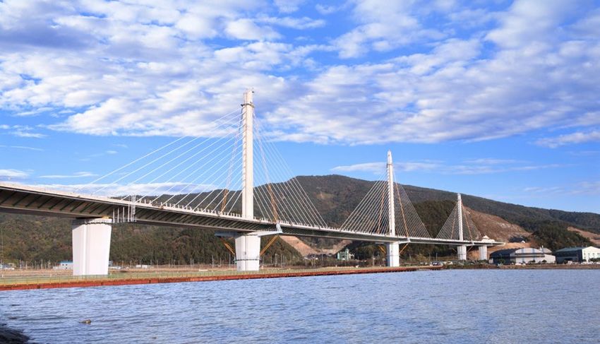
History
DYWIDAG-Systems International (DSI)       DSI Technology                                  Comprehensive Services
is a globally leading system supplier
of innovative technologies for the        In more than 90 countries and at 28             Our comprehensive services include the
construction industry.                    regional manufacturing sites, DSI               conception, design, planning and instal-
                                          develops, produces and supplies high            lation of its systems as well as quality
                                          quality systems such as DYWIDAG                 management and on site supervision.
Tradition                                 Post-Tensioning Systems, Geotechnical
                                          Systems and “Concrete Accessories”
The long tradition of DSI reaches         for the Construction industry. In accord-       Research & Development
back as far as 1865 – the founding        ance with our slogan “Local Presence
year of the German construction firm,     – Global Competence”, more than                 Continued investments in Research &
Dyckerhoff & Widmann AG (DYWIDAG).        2,100 specialized and experienced               Development and the resulting patent
DSI was founded in the year 1979 to       DSI employees ensure that DSI’s tech-           applications sustainably strengthen
market DYWIDAG Systems and tech-          nologies and know-how are available             the know-how available within the DSI
nical know-how around the world and       around the world. DSI offers quality on         Group. By offering innovative solutions
to develop innovative systems resulting   all levels – quality that is characterized      in accordance with superior quality
from its own R&D activities.              by creativity, reliability and profitability.   standards, we fulfill the constantly
                                                                                          changing requirements of our target
                                                                                          markets. It is our declared aim to
                                                                                          always be one step ahead.

                                                                                          Client Orientation
                                                                                          The needs and requirements of clients
                                                                                          and business partners are always of
                                                                                          paramount importance. Our company
                                                                                          is characterized by reliability, trust and
                                                                                          cooperation based on partnership.
                                                                                          We offer our clients the advantages of
                                                                                          an international system supplier with
                                                                                          a product range that is tailored to suit
                                                                                          individual requirements.

                                                                                          Certifications and
                                                                                          International Organizations
                                                                                          International organizations, trade
                                                                                          associations and standards commit-
                                                                                          tees are becoming more important in
                                                                                          times in which products and services
                                                                                          seem more and more interchangeable.
                                                                                          Organizations and trade associations
                                                                                          are cross-linked on a global basis and
                                                                                          promote the exchange of technology
                                                                                          and know-how across borders. We are
                                                                                          an active member in many International
                                                                                          Organizations to drive technical
                                                                                          developments.

1928: Saalebridge, Alsleben, Germany
First Bridge with prestressed Beam Tie developed by Dr.-Ing. Franz Dischinger

  4
History
Milestones
DYWIDAG Post-Tensioning Systems with the growing demand of modern Dependable corrosion protection
and Stay Cable Systems are world construction technology. methods, damper design, fire protec-
renowned for reliability and perfor- tion, vibration measurements and
mance; they are perfectly suitable In addition to traditional post-tensioning the recently developed DYNA® Force
for all applications in post-tensioned systems with bars, DSI offers a monitoring system significantly con
construction. They embrace the whole complete product line in strand post- tribute to the longevity of modern
spectrum from bridge construction and tensioning (bonded, unbonded and construction.
buildings to civil applications – both external) as well as stay-cable systems
above and below ground. to fulfill the changing requirements in
the industry today and tomorrow.
The first ever structure built with a
prototype DYWIDAG Post-Tensioning Our stay cable systems have always
System using Bars was the arch bridge combined the highest safety and
Alsleben (Germany) in 1927. From that reliability standards with excellent
time on, DYWIDAG has continuously economical efficiency in their research
improved its systems to keep up and development.
1972: 2. Main Bridge, Hoechst
Chemicals, Frankfurt, Germany
1995: Kap Shui Mun Bridge, Hongkong, China
DYNA Bond® Stay Cable Bridge with 176 cables
5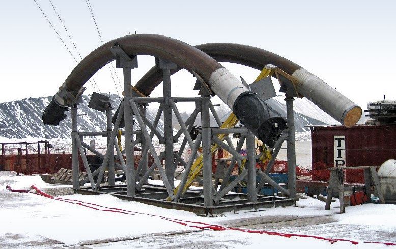
DYNA Grip® Stay Cable System

                                                               Leak Tightness
                                                Gap between threads is filled
                                               with corrosion protection com-
                                                pound for improved tightness

                                                Replaceability
                          Exchange of single strands including
                               PE-coating through anchorage
                                   —> no interruption of traffic

                                                                                                     Excellent Durability
                                                                                                     A watertight and adjustable sealing unit
                                                                                                     and strands with PE-sheathing up to the
                                                                                                     wedge meet highest demands. No devia-
                                                                                                     tion of strands in the wedge gripping zone

                                                                         High Fatigue Capacity
                                                                         Compliance with interna-
                                                                         tional fib and PTI standards

The DYNA Grip® Stressing Anchorage           High Fatigue Performance
consists of an anchor block in which
the strands are anchored by high             The system has proven its excellent           Tests
                                                                                          nn     on single strands under
fatigue 3 part-wedges. A ring nut            performance and fulfills the require-         reversed cyclic flexural loading with
is threaded onto the anchor block            ments of fib Bulletin 30 as well as PTI       45% and 60% GUTS, 2 million load
to transmit the cable force into the         for fatigue and tensile strength:             cycles with anchorages inclined by
structure via the bearing plate. A steel                                                   3.0° and additional angular deviation
pipe which incorporates bending and           Multiple
                                             nn         full size tests on cable sizes
                                                                                           between ± 10mrad and ± 35mrad
sealing provisions for the strands is part     from 7 to 156 strands
of the anchor block. A non-adjustable         The
                                             nn      system has been successfully         The leak tightness of the anchorage
anchorage with the same provisions for         tested in standard tests with a stress     area has been demonstrated for the
bending and sealing of the strands can         range of up to 200MPa at an upper          complete system and even meets strin-
be placed at the dead-end side.                stress limit of 45% GUTS and at            gent fib and Setra requirements with:
                                               2 million load cycles with anchorages
                                               inclined by 0.6°. In addition, full size    Up
                                                                                          nn    to 3m water head
                                               tests have been performed success-          Several
                                                                                          nn       load cycles in the longitudinal
                                               fully with an upper load of up to 60%       and transverse direction
                                               GUTS, up to 10 million load cycles          Temperature
                                                                                          nn             cycling 20–70°C
                                               and a stress range of up to 250MPa

  6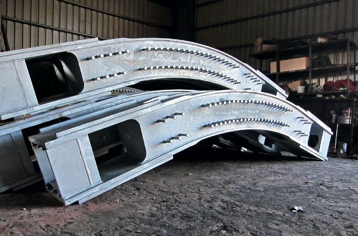
DYNA Grip® Stay Cable System
Free Length
Strands additio-
nally protected by
UV-resistant stay
pipe. Outer helical
Protection against Impact fillet for reducing
Usually used for vandalism wind-rain induced
protection. Can also vibrations
be upgraded with blast
and fire protection
Compaction Clamp
With long length and inner radius for optimized
cable bending and minimized transverse pressure.
Also serves as supporting structure in case
a guide deviator or damper is installed
Durability and high-quality Corrosion Protection
Strands are guided into the anchorage The anchorages have been designed Free length:
by an elaborate system that ensures for threading the strands including their
The
nn strands are protected by a multi-
both leak tightness and smooth PE-sheathing through the anchorage:
layer system of galvanized wires and
deviation:
Dismantling
nn of the strand’s are tightly sheathed by HDPE. A wax
Compressible
nn sealing plates ensure PE-sheathing is minimized to what is filling is used for the interstices in
water and even vacuum tightness absolutely necessary between
The
nn correct function can be checked The
nn factory applied corrosion protec- An
nn outer stay pipe made of
and even adjusted during inspection tion of the strands continues directly UV-resistant HDPE additionally
Bending
nn stresses are minimized by up to the wedges protects the strands and minimizes
a filter that arranges a straight-line Significant
nn reduction of the length rain-wind induced vibrations with an
entering into the wedge gripping area of anchorage area where interstices outer helical fillet that provides a low
are filled with corrosion protection drag coefficient
A
nn cap including filler material for the
protection of individual strands is compound. Both high durability and
placed in front cost savings in terms of additional
filling material are guaranteed.
Corrosion
nn protection resists
orrosivity class C5 in accordance
c
with ISO 12944
Replaceability of Strands Fast Construction Cycles
As the PE-coating is pulled directly Lightweight
nn equipment for strand No
nn exact dismantling of the strand’s
through the anchorage, an exchange of installation and stressing operations outer sheathing is necessary. In case
strands is possible at any time during is provided by DSI of stressing actions that are additio-
the service life of the bridge without The
nn use of tower cranes or other nally required, the strand sheathing is
the need for renewing or replacing any lifting equipment can be limited to a compressed by small tubes in front of
other cable components. minimum the wedges while the strand is pulled
through and elongated by the jack.
Strand
nn exchange is performed Non-protruding
nn recess pipes at the
directly at the anchorages > no additional formwork
pylon — A
nn compaction clamp, installed after
adjustment is required stressing on the strand bundle, keeps
There
nn is no need to remove the
the strand in a compact hexagonal
cable’s outer stay pipe – no dis
pattern.
ruptions to traffic.
7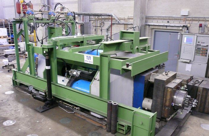
DYNA Grip® Stay Cable System

                                                Spacer

                              Sealing Plates

                             Ring Nut
                                                    Compression Plate

              Compression Tubes

                         Wedges                          Strands                             Compaction Clamp

                                                                                                                                   ∅P
oA

        ∅R

                                                          ∅T

                                                                                                       Vandalism Protection Pipe
                                                 Bearing Plate               Recess Pipe
  Cap           Anchor             D        C
                 Block                                                                                                    HDPE Sheathing
                                    B
                                                                   min LS

DYNA Grip® Anchorage – Technical Data
(forces calculated with strands 0.62" St 1620/1860)
                           Cable type *                                 DG-P4              DG-P7      DG-P12        DG-P19         DG-P31
                           No. of strands                                 4                  7          12            19             31

                     Forces [kN] **
                    Ultimate load at 100% GUTS                              1,116          1,953       3,348         5,301         8,649
             Service load at 50% GUTS for stay cables                        558            977        1,674         2,651         4,325
         Service load at 60% GUTS for extradosed tendons                     670           1,172       2,009         3,181         5,189

                   Dimensions [mm]
                     Bearing plate ***                    ¨A                190             250         300           370           460
                     Bearing plate ***                     C                 20              25          30            35            40
                 Bearing plate opening                    ∅T                112             145         183           219           267
                       Thread ****                         B                140             160         200           220           230
                        Ring nut                           D                 50              50          90           110           130
                        Ring nut                          ∅R                150             210         244           287           350
                      Dead anchor                          E                 50             90          120           120           135
                      Dead anchor                         ∅F                150             190         215           261           324
      Distance of compaction clamp, stressing end        min LS             520             650         880          1,080         1,350
        Distance of compaction clamp, dead end           min LD             400             510         740           940          1,210
                    HDPE sheathing                        ∅P                 63             90          110           125           160
* larger sizes on special request
** local design guidelines must be taken into account
*** dimensions correspond to concrete strength ≥ 35MPa (cylinder) at 45% GUTS according to PTI anchorage zone design
**** standard length, changeable on special request
Subject to modification

  8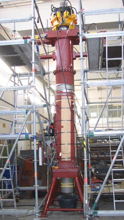
DYNA Grip® Stay Cable System

   HDPE Sleeve                                                    Dead Anchor

                                                                                               oA
                                                                                        ∅F
                                                             ∅T
                                                                        C       E
                                                  min LD

DG-P37      DG-P43    DG-P55   DG-P61    DG-P73     DG-P85   DG-P91      DG-P109     DG-P127
  37          43        55       61        73         85       91          109         127

10,323       11,997   15,345    17,019   20,367     23,715   25,389         30,411   35,433
 5,162       5,999     7,673    8,510    10,184     11,858   12,695         15,206   17,717
 6,194        7,198    9,207    10,211   12,220     14,229   15,233         18,247   21,260

 500          600       600      640      715         780     780            855       910
  45           60        60       65       70          75      80             85        90
 293          329       341      371      403         429     455            479       531
 240          250       270      275      290         310     310            340       350
 130          140       160      165      180         200     200            230       240
 378          420       440      480      536         600     600            636       700
 135          150       170      170      185         195     195            210       220
 354          398       420      450      490         522     550            586       645
1,500        1,690     1,750    1,920    2,070       2,170   2,340          3,020     3,390
1,360        1,550     1,610    1,780    1,930       2,020   2,200          2,880     3,250
 180          200       200      225      250         280     280            315       315

                                                                                               9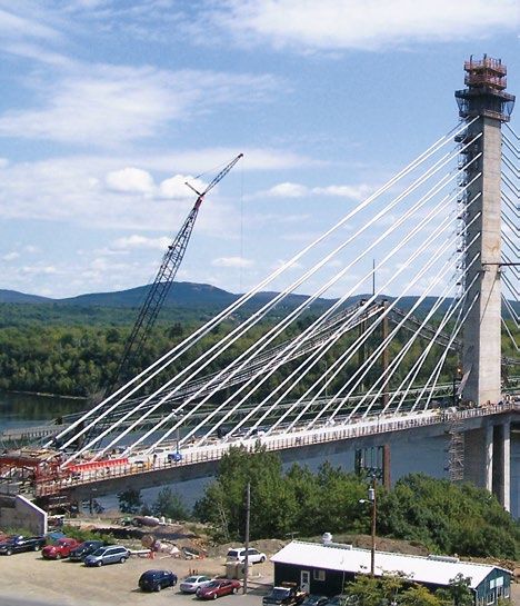
DYNA Grip® Stay Cable System – Optional Solutions
The DYNA Grip® Stay Cable System can be easily adjusted or upgraded if required:
 The
nn     length of the vandalism protec-       On
                                            nn    special request, guide deviators    DSI
                                                                                     nn       has patented an eccentric flange
  tion pipe can be adjusted to project        can be provided both at the deck and       connection between the recess pipe
  specific requirements to achieve any        at the pylon to:                           and the housing for the guide devi-
  requested height above the bridge           nnreduce cable bending at the              ator. The eccentric flange connection
  deck level.                                   anchorages                               ensures that eccentricities caused
                                              nndecrease cable vibrations                by wrong installation angles of the
                                                                                         recess pipe can be compensated.

                                                             Vandalism Protection Pipe

                                    Guide Deviator

      Eccentric Flange Connection

                                                                                              Deck Superstructure

 10
DYNA Grip® Stay Cable System – Optional Solutions
Eccentric Flange Connection
Guide Deviator
HDPE Sleeve
HDPE Sheathing
Pylon
11DYNA Grip® Stay Cable System – Clevis Anchorage
Architectural
nn requirements for the Fatigue tests were carried out at inclination of 0.6° – even towards the
design of stay cable bridges are the Technical University of Munich inflexible centerline – and an upper load
steadily increasing. Pylons often need in accordance with fib Bulletin 30 of 0.45 GUTS. They were carried out
to be as slim and elegant as possible. requirements. The tests respected an with a stress range of 200N/mm² at 2
Solutions
nn are needed in which the million load cycles.
stay cables are connected to the
structure outside of the pylon if the These dynamic tests, as well as the
space inside the pylon is insufficient subsequent static tensile tests, were
for common stay cable anchorages performed with outstanding success.
that are supported by bearing plates.
The clevis anchorage is not only suit-
DSI
nn developed the DYNA Grip® Clevis
able for stay cable bridges, but can also
Anchorage for strand cable types
be used for arch bridge hangers where
DG-P4 to DG-P61 as standard sizes
available space in the arch is too small
with additional types on request,
for aligning ordinary fixed anchors.
offering an economic alternative to
conventional systems that have been
used so far.
The
nn complete strand cable can
be easily pre-assembled on the
superstructure and is lifted into its
final position afterwards.
DSI
nn offers special tools for the
preassembly of the clevis as well as
the mounting of the pin into the clevis
hole.
Restressing
nn of individual strands
as well as the replacement of the
complete strand bundle is possible.
This
nn system also offers other
DYNA Grip® System advantages.
12DYNA Grip® Stay Cable System – Clevis Anchorage
Wedges
Wedge Keeper Plate
Anchor Block
Corrosion Protection
Compound
Sealing Plates
Pin Retainer
Spacer
Pin Clevis
•A
Compaction Clamp
•S
Compression Plate
oA
•P
G
HDPE Transition D C
Tube, Clevis Flange Tube
E B
DYNA Grip® Clevis Anchorage – Technical Data
(forces calculated with strands 0.62" St 1620/1860)
Cable type* DG-P 4 DG-P 7 DG-P 12 DG-P 19 DG-P 31 DG-P 37 DG-P 43 DG-P 55 DG-P 61
No. of strands 4 7 12 19 31 37 43 55 61
Forces [kN]**
Ultimate load at 100% GUTS 1,116 1,953 3,348 5,301 8,649 10,323 11,997 15,345 17,019
Service load at 50% GUTS 558 977 1,674 2,651 4,325 5,162 5,999 7,673 8,510
for stay cables
Service load at 60% GUTS 670 1,172 2,009 3,181 5,189 6,194 7,198 9,207 10,211
for extradosed tendons
Dimensions [mm]
Clevis ØA 140 200 230 270 330 355 390 415 450
Clevis ¨A 110 140 195 230 290 315 340 375 400
Clevis length B 330 370 480 580 685 720 770 875 890
Clevis C 60 75 100 127 158 170 185 212 220
Clevis D 85 105 140 175 220 235 255 295 305
Distance of compaction E 400 510 740 940 1,210 1,360 1,550 1,610 1,780
clamp
Gusset plate G 52 68 90 105 130 145 165 180 200
Gusset plate hole ØR 52 67 87 112 140 152 170 187 194
HDPE transition tube, ØS 110 140 200 225 280 280 315 355 355
clevis
HDPE sheathing ØP 63 90 110 125 160 180 200 200 225
* Bigger size on special request
** Load design guidelines have to be considered
13DYNA® Link Anchor Box System DYWIDAG’s DYNA® Link Anchor Box System is based on a conventional steel structure in which stay cables are anchored with standard DYNA Grip® anchorages. It features many advan- tages in comparison to conventional saddle solutions in which strands are guided through the pylon. The key features of the DYNA® Link Anchor Box System are: No nn friction problems; horizontal forces are transferred by the anchor box Cable nn anchorages located outside permit slender pylon shapes The nn pylon does not need to be accessible Stay nn cable assembly is just as flexible as in the case of common stay cables with anchorages that are located inside the pylon It nn is even possible to replace a complete strand bundle only on one side of the pylon There nn are no limitations in terms of deviation radii or differential forces; consequently, no limitations in any national regulations need to be taken into consideration The DYNA® Link Curved Anchor Box is economically designed using con- ventional steel construction standards to ensure capacity, serviceability and excellent fatigue characteristics. Testing is therefore not required. 14
DYNA® Link Anchor Box System

                               15
Saddle Solution
Saddle with Individual Tubes
If strands need to be guided through Strands
nn are placed into a multitude of
the pylon structure and a transfer of individual, curved recess tubes. The
forces by friction is required, DYWIDAG interstices between the saddle tube
offers a saddle in which the strands are and the recess tubes are grouted
guided from one side of the pylon to The
nn saddle itself is embedded into
the other: concrete
Centering Plate
Individual
nn strands can be replaced
Differential
nn forces are transferred by
friction
Curved Saddle Pipe
Solid Plate
16Saddle Solution
Interstices filled with Grout
Individual, curved Recess Pipes
17Fully Grouted Solutions
DYNA Bond® Anchorage
The DYNA Bond® Anchorage consists At
nn the final state of construction, all Additional Advantages:
of a conical steel pipe (bond socket) additional loads (live loads, vibrations
Minimized
nn bending effects at the
supporting a wedge plate in which the and earthquakes) are partly resisted
anchorage by placing an elastomeric
strands are anchored with high-fatigue by both wedges and grouted bond
bearing inside the recess tube
3-part wedges. A ring nut is fitted on socket.
the threaded end of the bond socket Reliable
nn corrosion protection for the
DYNA
nn Bond® Anchorages have an
and distributes the cable force through sensitive anchorage area, as all voids
excellent fatigue resistance because
a bearing plate into the structure. in the anchorage zone are filled with a
the bond action in the bond socket
stable and robust filler
During
nn the construction period – prior substantially reduces the magnitude
of the dynamic loads reaching the Enhanced
nn fire resistance and protec-
to grouting the bond socket – all the
wedge anchorage. Fatigue tests tion against vandalism, impact loads
applied loads are supported directly
have proven a stress range of up to and blast effects
by the wedges
240N/mm2 at an upper load of 45% Easy
nn fixation of external dampers
GUTS and 2 million load cycles. directly on the grouted stay pipe
A
nn special patent protected sealing
provision allows to grout the
anchorage area only so that the free
length remains without grout
Boot
Elastomeric Bearing
Ring Nut Strands
Spacer
Filling Material
Wedges HDPE
Sheathing
Recess Pipe
Bond Socket
Bearing Plate
Cap Wedge Plate
18Fully Grouted Solutions
Saddle with Anchor Groove and Pin
The saddle transfers differential forces via a shear nose with pin into the pylon concrete construction.
Strands
nn (without PE coating inside An
nn inner, curved saddle pipe is transferred via a shear nose (anchor
the saddle) are guided in a curved guided through an outer recess pipe groove – pin construction)
tube and injected in the deviation that is embedded into the concrete The
nn strand bundle including saddle
area using special grout Differential
nn forces in the stays at pipe can be exchanged if necessary
both sides of the saddle are reliably
Steel Saddle Pipe
Steel Recess Pipe
Grout
Strands (without PE sheathing
Anchor within the saddle area)
Pin
Anchor
Groove
Strands
Exit Pipe
HDPE Sleeve
HDPE Sheathing
Steel Recess Pipe
with Anchor Groove
Steel Saddle Pipe with Anchor Pin
Grout
19Strand and Wedge
DYWIDAG Stay Cables use strands that Epoxy Coated Strands
meet the requirements of fib and PTI-
Recommendations for stay cables, Epoxy coated strand is manufactured in Epoxy
nn material reduces fretting action
ASTM, BS as well as other national or compliance with ISO 14655:1999. The between the individual wires and
international standards. 3-part wedges are specially designed cushions adjacent strands in devia-
for epoxy coated strands. The teeth tion areas
Generally, the following types of strands penetrate through the coating so that The
nn excellent bond of the epoxy
are used: they grip into the wires of the strand. with the steel wires and the ductile
7
nn cold-drawn galvanized wires Fatigue
nn tests conducted on behavior of the epoxy material
PE-coated
nn with minimum thickness single-strand tendons have proven eliminate the possibility of damage to
of > 1,5mm in accordance with fib a dynamic stress range of up to the corrosion protection barrier during
Bulletin 30 260N/mm2 (upper stress 0.45 GUTS stressing
Wax
nn as a void filler for the interstices at 2 million load cycles).
between wires and PE coating Cold-drawn
nn 7-wire strand is coated
Diameters
nn up to 0.62" and steel with epoxy resin in the shop
grades up to 1,860mm2 Interstices
nn between the 7 wires are
Low
nn relaxation strand completely filled with epoxy resin,
thus providing excellent and robust
Strands are anchored with specially long-time corrosion protection.
treated 3-part wedges that are charac-
terized by high fatigue resistance.
Wedge for Galvanized Strand
Wedge for Epoxy Strands Epoxy Coated Strand
20Strand and Wedge
Outer Stay Pipe
Standard Pipe
HDPE pipes serve as protection
against environmental influences
and are typically used as outer
covers of DYWIDAG Stay Cables.
Main characteristics:
Wind
nn load reduction at the cable
Outer
nn helix with demonstrated
efficiency against rain-wind induced
cable vibrations
Co-extruded
nn or fully colored pipes Standard Duct
Wide
nn range of colors
The
nn excellent UV-resistance has been
proven in accelerated aging tests
Steel
nn or stainless steel pipes are
available on special request
Slim Duct
For long span bridges, lateral wind
loading at the cables needs to be
taken into account for pylon design.
To reduce the wind load, DSI offers slim
sheathing with reduced pipe diameters.
Slim Duct
HDPE Sheathing with Helix
21Cable Damping
Slender supporting structures and Depending on the respective cable Cables start vibrating when they are
long cable lengths make stay cables parameters, each cable is more or less excited. Please find following some
susceptible to vibrations. Big vibration prone to vibration. Longer cables are excitation causes and methods for
amplitudes may result in damages to more likely to vibrate than short ones. mitigating their effects.
the cable due to bending and fatigue Nevertheless, cables with lengths
loads. This decreases a cable’s above 200m have been installed
durability and may even endanger without additional dampers without any
structural safety. vibration problems. On the other hand,
even very short cables sometimes need
dampers. By experience, DSI recom-
mends to increase a cable’s inherent
damping by using additional damping
devices for cable lengths above 80m.
22Cable Damping
Excitation Causes
Buffeting Galloping Parametric Excitation
Wind
nn causes drag, lift and moment Galloping
nn affects rectangular shapes Parametric
nn excitation is caused if the
forces on cables that result in or round shapes with asymmetry. excitation acts on other parts of the
cable vibrations. Depending on If the wind speed is above a critical structure (such as the pylon), and if
the boundary conditions, inherent value, vortexes detach from the this vibration is transferred into the
damping of a stay cable without edges and create similar effects as cables.
additional damping might not be high vortex shedding. However, contrary
enough to decrease these vibrations to vortex shedding, galloping results DSI not only supplies the appropriate
to an acceptable amplitude. in high amplitude vibrations. damping devices but also supports
bridge designers and owners in
Vortex-shedding Wake Galloping choosing a damping concept that is
Uniform
nn wind flow causes turbulent Wake
nn Galloping occurs at cables that customized to their specific project
vortices to detach, alternating from a are closely spaced in wind direction. needs.
cable’s top and bottom side, so that Vortexes behind one cable excite the
vibrations are caused. The amplitudes cable that is next to it and lead to Outer Helical Fillet
are usually small compared to the vibrations. To
nn mitigate rain-wind induced
cable diameter. However, resonance v ibrations, a 3mm high double
of the vortex shedding frequency and Iced Galloping helical fillet is applied on the
cable eigenfrequencies can result in Ice
nn that sticks to a round cable can surface of outer stay pipes
larger amplitudes. alter its cross section in such a way Different
nn diameters have been tested
that galloping occurs above a critical in climatic wind tunnel tests
wind speed. Demonstrated
nn drag coefficient of
CD = 0,6 for large cable diameters
Rain-Wind induced Vibrations
During
nn specific combinations of rain
intensity, wind speed, wind direction
and cable inclination, water rivulets
arrange at the cable’s top and bottom
surface. Due to wind, they move a
few degrees around the cable circum-
ference and induce vibrations into the
cable. This happens at relatively low
wind speeds.
1.1
1.0
Drag coefficient CD
0.9
0.8
0.7
0.6
0.5
0.5 1.0 1.5 2.0 2.5 3.0 3.5 4.0 4.5 5.0 5.3
Reynolds number Rc ×105
α = 0°
α = 180°
23Cable Damping
Damper Design 1.25 16.5
Sufficient damping prevents cables
from vibrating. DSI recommends 1.00 13.2
damping values of at least 3–4%
logarithmic decrement δ, depending on
each cable’s boundary conditions and 0.75 9.9
on project specific requirements. These ζ [%] Sc
damping values can usually not be
achieved by inherent cable damping so 0.50 6.6
that additional damping is required.
External Viscous Damper 0.25 3.3
External viscous dampers provide very
0 0
effective supplementary damping.
0 400 800 1,200 1,600 2,000
Special
nn software developed for DSI c [kN · s/m]
Efficient
nn dampers can be computed
for each cable taking into account Mode 1 Mode 2 Mode 3 Mode 4 Mode 5
several vibration modes
In
nn plane, the damper is sufficient to
also suppress out of plane vibrations
Slender
nn and aesthetic design;
available in several colors
24Cable Damping
Internal Viscous Damper
In addition to external viscous dampers,
DSI also offers internal viscous
dampers that are attached to the exit
pipe.
Damping
nn forces are transmitted from
the damper through its steel housing
and exit pipe into the recess pipe,
from where they are transferred into
the superstructure
Housed
nn dampers are advantageous
if support constructions would other-
wise be needed to connect dampers
and bridge deck
Since
nn DSI housed dampers do not
require a connection point on deck,
they can be used at virtually any
cable position
Increased
nn durability is a benefit
of housed dampers: they are not
affected by weathering
Internal Rubber Damper
Especially used for short and medium
cable lengths
Internal
nn rubber dampers are placed
inside the exit pipe parallel to the
cable axis
Their
nn elastomeric material dissipates
vibration energy while deforming
when subject to shear stress
25Fire Protection
Lightning, a car accident or other Fire Protection Mats for the Free Cable Length
external incidents may cause fire on
a bridge. In that case, the main parts Special
nn fire protection mats resist a Used
nn for the free length of the stay
of the stay cable system need to be hydrocarbon fire with 1,100°C for at cable
protected against damage. least 30 minutes without heating up Covered
nn by standard HDPE sheathing
the strands to more than 300°C and
Mats
nn have a hydrophobic behavior to
with no permanent decrease in load
avoid water absorption
capacity
Possible
nn upgrade for blast protection
Strand Bundle Fire Protection Mat
HDPE Sheathing
26Fire Protection
Anchorage Area
Steel
nn parts in the anchorage area Fire
nn protection coating fulfills the
can be coated with a special fire highest requirements according
protection coat that is intumescent Bearing Plate to standard ISO 12944, corrosivity
under heat impact and thus protects class C5
the steel parts
Protection
nn has been demonstrated
during laboratory tests
Cap
Intumescent Coating
Ring Nut
Anchor Block
Anchorage Protection System
Coating before Fire Testing Intumescent Coating after Fire Testing
27Full Size Testing
DYWIDAG Stay Cables have been Fatigue and Tensile Testing
successfully tested in static and
fatigue tests in compliance with fib Applying
nn 2 million load cycles DYWIDAG Stay Cable testing has
and/or PTI recommendations. Tests also been successfully conducted in
Stress
nn range of 200N/mm²
have been conducted in collaboration additional full size tests with increased
with renowned Universities such as Upper
nn load level of 45% GUTS
requirements in terms of upper load
CTL, TU Munich, TU Vienna or DTU Inclined
nn anchorages of 0.6° and additional angular deviation of the
Copenhagen. cable system
28Full Size Testing
2 Million Load Cycles
with additional
Transverse Deflection
Application
nn of 2 million load cycles
Stress
nn range of 100N/mm²
Upper
nn load level of 60% GUTS
Anchorages
nn inclined by 0.6°
Deviation
nn of ± 25mrad in transversal
direction
Increased Load Cycle
Testing – 10 Million Cycles
Application
nn of 10 million load cycles
Stress
nn range of 200N/mm²
Upper
nn load level of 45% GUTS
Anchorages
nn inclined by 0.6°
29Full Size Testing
Monostrand Fatigue Testing under
Reversed Cyclic Flexural Loading
A series of bending fatigue tests on Application
nn of 2 million load cycles
galvanized, waxed and PE-coated 7 Different
nn upper load levels varying
wire strands 0,62" with an ultimate from 45% to 60% GUTS
tensile strength of 1,860N/mm²
Static
nn inclination at the anchorage
were successfully performed. They
between 0,6° and 3.0°
proved that the standard protective
measures of the sealing unit within the Additional
nn angular deviation at
DYNA Grip® Anchorage are effective the center of the strand between
for fatigue bending without the addi- ± 10mrad and 25mrad
tional use of a guide deviator.
30Full Size Testing
Leak Tightness Test
DSI anchorages are fully resistant
to any infiltration of water. Tested
according to fib and Setra requirements
with:
Up
nn to 3m water head
Several
nn load cycles in longitudinal
and transverse direction
Temperature
nn cycle 20°C – 70°C
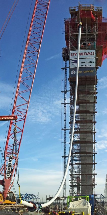
31Cable Installation DSI has developed various methods to optimize and simplify cable installation procedures depending on site specific space and time constraints. The nn outer sheathing is welded to its required length directly on site using heated tool welding and is then lifted into an inclined position Strands nn are uncoiled either from wooden reels or are provided reel-less. They are installed and stressed one by one using lightweight equipment Strand nn installation is performed using small winches or pushing devices Hardware nn configuration can be adjusted to site conditions to ensure a fast, customized solution that minimizes costs and cycle times If required, the complete cable can also be preassembled on the ground first. Afterwards, nn strands are installed into the sheathing, and the complete cable is lifted into its final position Subsequently, nn all strands are stressed 32
Cable Installation

                     33
Stressing
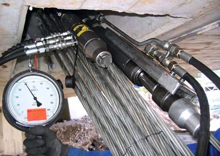
DYWIDAG stressing equipment is designed to ensure an economic and convenient installation process.
ConTen Stressing
The patented ConTen System uses a turning the ring nut. Special compact The
nn same economic type of hydraulic
monojack that is hydraulically coupled gradient jacks are available for this pump can be used for both stressing
with a control unit. The system is purpose. systems. The pump is light, robust
applicable both for DYNA Grip® and and has proven its reliability in many
Gradient
nn jacks may be moved fully
DYNA Bond® Stay Cable Systems. stay cable projects
assembled or disassembled into their
Every
nn single strand is stressed main components so that they fit
individually even through small openings
A
nn special calculation method –
developed by DSI – determines
the force for the first strand and Change of Strand Force depending on
one Sequence after Stressing Strand i [kN]
Force in each Individual Stressed Strand of
the corresponding forces for all the Number of Stressed Strands
subsequent strands
110,0
This
nn allows monitoring the stressing 100,0
operation up to the required final
cable force 90,0
80,0
Equal
nn forces are achieved in all
strands within one cable at the end of 70,0
the stressing operation 60,0
Influences
nn of temperature and 50,0
load changes during stressing are 40,0
automatically eliminated
30,0
0 10 20 30 40 50 60
In case of very short strand elongation
Number of Installed and Stressed Strands
values or if the cable force needs to
be adjusted, retensioning or releasing First Stressing Sequence
of the complete cable is possible by Second Stressing Sequence
34Stressing
>1
,1
D
00
•
Jack type Cable Type Capacity D LPRO Weight Strand
size protrusion
LPRO
[kN] [mm] [mm] [kg] [mm]
ConTen Jack All Types 180 kN 182 ∅ 73 950 19 1,100
12
19 C 27 3,500 560 × 610 725 400 540 *
31
37 C 37 4,200 610 × 610 820 520 660 *
Gradient Jacks 55
C 61 6,800 700 × 700 865 700 680 *
(DYNA Grip® **) 61
D
73 C 73 8,400 780 × 760 965 820 780 *
91 C 91 11,000 870 × 870 1,213 2,100 890 *
109 1,160 ×
C 127 16,000 1,178 3,100 995 *
127 1,046
L
* measured from the top of the bearing plate PR
O
** for multistrand jacks for DYNA Bond®, please contact DSI
Gradient Jack Standard Hydraulic Pump
35DYNA Force® Elasto-Magnetic Sensor
This system has been developed to measure or monitor forces within single strands of a stay cable during the construction
progress as well as during the entire service life.
Functional Principle System Components System Advantages in
Comparison to other
The
nn permeability of steel to a mag- Portable
nn Power Stress Unit Measuring Systems
netic field changes with the stress Sensor
nn with lead wire
level in the steel The
nn system cannot be overloaded
Multiplexer
nn Box for connecting more
By
nn measuring the change in a than one sensor to the Power stress Maintenance
nn free
magnetic field, the magnitude of the Unit at the same time No
nn direct contact between the sensor
stress in the steel element is obtained and the strand/bar
Automated
nn measurement on several
Data
nn is gathered and elected by sensors through multiplexer Resistant
nn against dust and humidity
special system components
Transfer
nn of data by WLAN connection Up
nn to 2% of measurement accuracy
Data
nn can be handled using a or cellular wireless connection
conventional computer
36DYNA Force® Elasto-Magnetic Sensor
Quality Assurance
All
nn DYNA Force® Sensors are profes-
sionally made in a quality controlled
facility
Every
nn DYNA Force® Sensor is
tested and individually packed and
numbered at the DSI facility before it
is sent to the job site
DSI
nn has carried out additional tests
to simulate the performance of the
system when placed within the
anchorage zone of stay cables
Practical Applications
When
nn a DYNA Force® Sensor is
installed on a strand, the force in it
may be obtained directly by merely
attaching the leads from the sensor
to a portable Power Stress Unit
No
nn other equipment is needed
DYNA
nn Force® Sensors have been
used in many bridge and building
structures for the past several years
37Cable Inspection
Visual Inspection
Visual inspection is a key measure Cameras
nn are placed on an automo- Possible
nn defects can be detected
during cable maintenance and inspec- tive cable robot that moves along the quickly
tion outer surface of the cable sheathing Afterwards,
nn detailed examinations
DYWIDAG
nn visual inspection keeps Cable
nn surface is checked for can be limited to critical spots
traffic disturbances to a minimum damages or color changes
38Cable Inspection
Vibration Measurement
Cable forces and cable damping values Measurement
nn at one cable only takes teristics and can be calculated from
are very important both during and after a few minutes the vibration measurement
construction as well as for monitoring. Each
nn cable has an individual vibra- The
nn obtained cable eigenfrequencies
DSI offers vibration measurement tion characteristic depending on are used to calculate tensioning
for tension members to quickly and cable force, dimensions, the type of forces
efficiently determine both cable forces anchorage and on possible cable Damping
nn values can be calculated
and damping values. supports by determining the decay of vibration
A
nn 3-dimensional accelerometer, Eigenfrequencies
nn and eigenmodes amplitudes
placed on the cable, registers its correspond to the vibration charac-
movements
Magnetic Flux Leakage
Inspection
Magnetic flux leakage inspection is a
non-destructive testing method that
detects changing magnetic properties.
DSI uses this method to determine
corrosion, breaks or cuts to strands.
Magnetic flux leakage inspection
is a very economic and fast testing
procedure:
The
nn equipment can be adapted to fit
different pipe diameters
Only
nn the deck anchorage needs
to be accessible for mounting the
equipment. The measuring equipment
is moved by hoists and winches in
the free cable length, thus minimizing
traffic disturbances
The
nn whole strand bundle can be
magnetized, which allows checking
even strands on the inside
There is no need to remove HDPE
sheathing: The equipment moves
along the pipes, and the magnetic field
permeates the HDPE sheathing.
39References
Stay Cable References
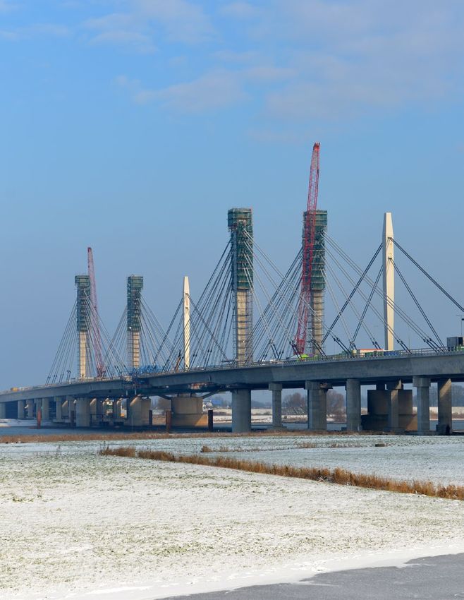
Bridge over the River Waal,
Ewijk, Netherlands
Design, supply and installation of
40 Type DG-P 73 DYNA Grip® Stay
Cables as well as 40 Type DG-P 91
DYNA Grip® Stay Cables with slim
duct sheathing. Supply and instal-
lation of external damper system
Dr. Franjo Tudjmann Bridge,
Dubrovnik, Croatia
Supply and installation of 38 Type
DB-P 27 and DB-P 61 DYNA Bond® Stay
Cables. Installation of adaptive dampers
Elbe Bridge Schoenebeck,
Magdeburg, Germany
Supply and installation of
36 Type DG-P 31, 37 and 55
DYNA Grip® Stay Cables.
Magnetic flux leakage inspection
and vibration measurements
during compliance testing
40References
Harbor Drive Suspension Bridge,
San Diego, USA
Design, supply and installation
of two main stay cables and
DYWIDAG Strand Tendons, 12-0.6",
19-0.6", 37-0.6", 37-0.62" and
43-0.6" in stainless steel sheathings
that were used as back stays
Pitt River Bridge,
Vancouver, Canada
Supply of
96 Type DG-P 31 and DG-P 61
DYNA Grip® Stay Cables. Design,
supply and installation of an
external damper system
Sae Poong Bridge,
Gwangyang, Korea
Supply and installation of 90 Type
DG-P 55 and DG-P 61 DYNA Grip®
Stay Cables; 24 Type DG-P 12, 37
and 61 Transversal DYNA Grip®
Stay Cables with Clevis Anchorages;
6 Type DG-P 19 DYNA Grip® Tie-Down
Cables; installation of external dampers
41References
Extradosed Bridge References
Trois Bassins, La Réunion
Supply and installation of 34 Type
DG-P 37 DYNA Grip® cables with fully
grouted saddle. Rental of equipment
and technical assistance on site. Fire
protection over the full cable length
Domovinski Bridge, Zagreb
Design, supply and installation of
32 Type DB-P48 DYNA Bond® Stay
Cables with fully grouted saddle
42References
Považská Bystrica, Slovakia
Supply and installation of 56 Type
DG-P 37 DYNA Grip® cables with fully
grouted saddle. Rental of equipment
Photo reprinted courtesy of
Doprastav, a.s., Slovakia
Earthquake Memorial
Bridge, AJK, Pakistan
Design and supply of Type DB-P
19 and 27 DYNA Bond® Stay
Cables with fully grouted saddle
43References
Arch Bridge References and Special Applications
Lake Champlain Arch Bridge, USA
Design, supply and installation of
64 Type DG-P 7 DYNA Grip® Hangers
Aguascalientes Arch Bridge, Mexico
Supply and installation of 34 Type
DG-P 19 DYNA Grip® Hangers
Gajo Arch Bridge, South Korea
80 Type DG-P 12 DYNA Grip® Hangers
44References
Wind Turbine, Vaasa, Finland
Design, supply and installation of Type
DG-P 37 DYNA Grip® Stay Cables
Photo reprinted courtesy of
Mervento Ltd, Finland
Apollo Arch Bridge over the Danube
River, Bratislava, Slovakia
Supply of 66 Type DG-P 12
DYNA Grip® Hangers; technical
support and rental of equipment
45Australia Croatia Greece
DYWIDAG-Systems International Pty. Ltd. PRESS-KON Geotechnical Systems
25 Pacific Highway Obala Hrvatskog HELLENPLAN
Bennetts Green, NSW 2290 narodnog preporoda 6 4 K. A. Dimitriou Street
Australia 21000 Split Spata 19004
Phone +61-2-49 48 90 99 Croatia Greece
E-mail dsi@dywidag.com.au Phone +385-21-34 27 66 Phone +30-210-663 57 86
www.dsiminingproducts.com/au E-mail info@dywidag-systems.com
Post-Tensioning Systems
Austria Czech Republic Kostantinos Zervas
DYWIDAG-Systems International GmbH DYWIDAG-Systems International 34th Sintagmatos Pezikon 5
Alfred-Wagner-Strasse 1 Jilemnického 29/46 Pireas TK 18532 Athens
4061 Pasching/Linz 772 00 Olomouc-Nedvězi Greece
Austria Czech Republic Phone +30-213-0227 363
Phone +43-7229-610 49 0 Phone +420-585-94 10 76
E-mail office@dywidag-systems.at Indonesia
www.dywidag-systems.at Denmark PT DELTA SYSTECH INDONESIA
AAGE CHRISTENSEN A/S Wisma Ritra 2nd Floor
Belgium Skelmosevej 10 Jl. Warung Buncit Raya No. 6
DYWIDAG-Systems International N.V. 2500 Valby Jakarta – 12740
Philipssite 5, bus 15 Denmark Indonesia
Ubicenter Phone +45-36-132 542 Phone +62-21-797 02 89
3001 Leuven E-mail info@aagechristensen.dk E-mail prestress@dsi-indonesia.co.id
Belgium
Phone +32-16-60 77 60 Egypt Israel
E-mail info.be@dywidag-systems.com MISR DYWIDAG EVEN GEV Ltd.
www.dywidag-systems.com 20 Haroun Street Emanuel Building
El Dokki 31 Ha’Barzel Str.
Brazil Giza Ramat Ha’Hayal
PROTENDIDOS DYWIDAG Ltda. Egypt Tel Aviv 69710
Rua Iaiá, 150 – 10° andar – Cj. 102 Phone +20-2-37 61 48 69 Israel
Itaim Bibi E-mail mail@misrdywidag.com Phone +972-77-501 00 56
04542-060-São Paulo/SP
Brazil SPENSY Italy
Phone +55-11-21 31 37 00 15, Nables St. DYWIT S.P.A.
E-mail vendas@dywidag.com.br 12345 Mohandessin – Giza Viale Europa 72 Strada A 7/9
www.dywidag.com.br Cairo 20090 Cusago (MI)
Egypt Italy
Canada Phone +20-2-33 05 82 20 Phone +39-02-901 65 71
DYWIDAG-Systems International Canada Ltd. E-mail info@dywit.it
37 Cardico Drive Finland www.dywit.it
Gormley, ON L0H-1G0 TENSICON OY
Canada Rattitie 17 Japan
Phone +1-905-888 8988 007700, Helsinki 77 SUMITOMO ELECTRIC INDUSTRIES, LTD.
E-mail ecd@dsiamerica.com Finland Sales Department
www.dsicanada.ca Phone +358-500-406 438 Special Steel Wire Division
www.tensicon.fi 1-1-1, Koya-kita Itami,
DYWIDAG-Systems International Canada Ltd. Hyogo, 664-0016
19433 – 96th Avenue, Suite 103 France Japan
Surrey, BC V4N 4C4 DSI-Artéon SAS Phone +81-72-771-0966
Canada Rue de la Craz
Phone +1-604-888 8818 Z.I. des Chartinières Korea
E-mail wcd@dsiamerica.com 01120 Dagneux DYWIDAG-Systems Korea Co. Ltd.
www.dsicanada.ca France 5th Floor, Spring Morning B/D
Phone +33-4-78 79 27 82 8, Mabang-ro, Seocho-gu
Chile E-mail dsi.france@dywidag.fr Seoul 137-894
DSI Chile Industrial Ltda. www.dywidag-systems.fr Korea
Las Encinas #1387, Valle Grande Phone +82-2-34 72 01 41
Lampa – Santiago Germany E-mail dywidagkor@gmail.com
Chile DYWIDAG-Systems International GmbH www.dsikorea.co.kr
Phone +56-2-596 96 61 Germanenstrasse 8
E-mail construccion.chile@dsilatinamerica.com 86343 Koenigsbrunn Lebanon
www.dsi-chile.com Germany SOPREL Liban SAL
Phone +49-8231-96 07 0 Liban Cable Street
China E-mail geotechnik@dywidag-systems.com Halate
DYWIDAG-Systems International www.dywidag-systems.de Lebanon
Far East Ltd. Phone +961-9-44 88 60
Room 2306 DYWIDAG-Systems International GmbH E-mail contact@soprel-liban.com
CC Wu Building Max-Planck-Ring 1
302-308 Hennessy Road 40764 Langenfeld Lithuania
Wanchai Germany Delta Nova
Hong Kong Phone +49-2173-79 02 0 Užupio g. 30
Phone +852-28-33 19 13 E-mail suspa@dywidag-systems.com LT-01203 Vilnius
E-mail dsihk@dsife.com.hk www.dywidag-systems.com/emea Lithuania
Phone +370-5272-53 08
Colombia DYWIDAG-Systems International GmbH E-mail info@deltanova.lt
DSI Colombia S.A.S. Schuetzenstrasse 20 www.deltanova.lt
Carrera 43A No. 8 sur – 15 Oficina 403 14641 Nauen
Edificio Torre Oviedo Germany Mexico
Medellín, Colombia Phone +49-3321-44 18 0 DS International México, S.A. de C.V.
Phone +57-4-403 12 00 Av. Aviación No 1002 Bod. 15
E-mail ventascolombia@dsilatinamerica.com DYWIDAG-Systems International GmbH Parque Industrial FERRAN I
www.dsi-colombia.co Siemensstrasse 8 San Juan de Ocotán
85716 Unterschleissheim Zapopan, Jalisco 45019
Germany México
Phone +49-89-30 90 50 100 Phone +52-33-33 66 57 94
E-mail dsihv@dywidag-systems.com E-mail dsimexico@dsiunderground.com
www.dywidag-systems.com www.dsiunderground.com
46Netherlands Singapore USA
DYWIDAG-Systems International B.V. UTRACON STRUCTURAL SYSTEMS PTE LTD DYWIDAG-Systems International USA Inc.
Veilingweg 2 7 E Pioneer Sector 1 320 Marmon Drive
5301 KM Zaltbommel Singapore 628446 Bolingbrook, IL 60440
Netherlands Phone +65-64-15 30 78 USA
Phone +31-418-57 89 22 E-mail utracon@utracon.com Phone +1-630-739 1100
E-mail email@dsi-nl.nl www.utracon.com E-mail dsiamerica@dsiamerica.com
www.dywidag-systems.com www.dsiamerica.com
Slovakia
Norway Doprastav, a.s. DYWIDAG-Systems International USA Inc.
Dywidag Norge AS Závod Prefa 2154 South Street
Norvald Strands veg 21 Drieňová 31 Long Beach, CA 90805
2206 Kongsvinger 821 01 Bratislava USA
Norway Slovakia Phone +1-562-531 6161
Phone +47-67-06 15 60 Phone +421-2-48 271 130 E-mail dsiamerica@dsiamerica.com
E-mail adm@dywidag-norge.no www.dsiamerica.com
www.dywidag-norge.no South Africa
Amsteele Systems
Peru Unit 20, Lothlorien Industrial Park
DSI Peru S.A.C. Tedstone Road, Wadeville
Calle Uno Oeste 0061 Of. 103 Albemarle 1410
San Isidro-Lima 1 / Peru South Africa
Phone +51-1-224 54 54 Phone +27-11-827 6721
E-mail construccion.peru@dsilatinamerica.com
www.dsi-peru.com Spain
DYWIDAG SISTEMAS CONSTRUCTIVOS, S.A.
Poland Avd/de la Industria, 4
DYWIDAG-Systems International Sp. z o.o. Pol. Ind. la Cantuena
ul. Bojowników o Wolność i Demokracje˛ 38/121 28947 Fuenlabrada (Madrid)
41-506 Chorzów Spain
Poland Phone +34-91-642 20 72
Phone +48-32-241 09 98 E-mail dywidag@dywidag-sistemas.com
E-mail dsi-polska@dywidag-systems.com www.dywidag-sistemas.com
www.dywidag-systems.pl
Switzerland
Portugal SpannStahl AG
DYWIDAG SISTEMAS CONSTRUCTIVOS, SA Industriegebiet
Rua D. Manuel, n.º 24 A Waesseristrasse 29
Quinta da Parreirinha 8340 Hinwil/ZH
2695-003 Bobadela (Loures) Switzerland
Portugal Phone +41-44-9 38 97 97
Phone +351-21-892 28 90 E-mail info@spannstahl.ch
E-mail dywidag@dywidag-sistemas.com www.spannstahl.ch
Qatar Taiwan
QACS (Qatar Australien Construction Systems DYWITECH Co. Ltd.
W.L.L.) 13th Fl.-3, No. 163, Sec. 1, Keelung Road
Abu Hamur, Villa No. 63531, Taipei 110
Opposite to Abu Hamur Station Taiwan, R.O.C.
P.O. Box 24893 Phone +886-2-27 48 10 76
Doha / Qatar
Phone +974-44-58 04 11 Thailand
D-Tech Postten Co., Ltd.
Russia 91/22 Suwinthawong road
DSI-PSK OOO Minburi district, Minburi
Joint Venture Bangkok 10510
Leninsky prospekt, Thailand
d. 105, korp. 4 Phone +66-2543-77 61
Moscow 119421
Russia Turkey
Phone +7-495-234 25 02 DIVIGER Yapi Teknoloji A.S.
www.psk-holding.ru Yildiz Posta Cad.
Ayildiz Sitesi 30/15
Saudi Arabia 34349 Istanbul-Gayrettepe
DYWIDAG-Systems International „DSI“, Riyadh Turkey
P.O. Box 53039, Phone +90-212-234 56 12
Riyadh, 11583 E-mail diviger@diviger.com
Saudi Arabia
Phone +966-1-46 50 311 ext. 106 United Arab Emirates (U.A.E.)
IGS (Italian Gulf Specialist)
BIC Prestressed Concrete Bel Houl Group Building – Office 403, Al Garhoud
P.O. Box 101688, P.O. Box 124 073
Riyadh, 11665 Dubai
Saudi Arabia U.A.E.
Phone +966-1-278 14 79 Phone +971-4-236 96 41
E-mail info@bic-ksa.com
www.bic-ksa.com United Kingdom
DYWIDAG-Systems International Ltd.
Serbia & Montenegro Northfield Road
EnCon d.o.o. Southam, Warwickshire, CV47 0FG
3, Cara Lazara Street Great Britain
11000 Belgrade Phone +44-1926-81 39 80
Serbia & Montenegro E-mail sales@dywidag.co.uk
Phone +381-11-328 12 73 www.dywidag.co.uk
47You can also read