Edge Grinding Characteristics of Display Glass Substrate - MDPI
←
→
Page content transcription
If your browser does not render page correctly, please read the page content below
Journal of
               Manufacturing and
               Materials Processing

Article
Edge Grinding Characteristics of Display Glass Substrate
Dennis Wee Keong Neo                      , Kui Liu * , Rui Huang and Hu Wu

                                            Singapore Institute of Manufacturing Technology, 73 Nayang Drive, Singapore 637662, Singapore;
                                            dennis_neo@simtech.a-star.edu.sg (D.W.K.N.); huang_rui@simtech.a-star.edu.sg (R.H.);
                                            hwu@simtech.a-star.edu.sg (H.W.)
                                            * Correspondence: kliu@simtech.a-star.edu.sg; Tel.: +65-6793-8565

                                            Abstract: Display glass substrate as a brittle material is very challenging to machine due to its
                                            excellent physical, mechanical, electrical, and optical properties such as high hardness, high strength,
                                            high wear resistance, good fracture toughness, good chemical stability, and good thermal stability.
                                            On the basis of Griffith fracture mechanics, our theoretical analysis indicated that edge grinding of
                                            the display glass substrate is under brittle mode when grinding with the given conditions, which
                                            was verified by the experimental studies of ground glass edge surface topography and fractured
                                            surface obtained. Grinding force (Fy ) in the vertical direction was much larger than grinding force
                                            (Fx ) in the horizontal direction, causing a large compressive stress acting on the grinding glass edge.
                                            Grinding torque was slightly increased with the increase of grinding speed. Grinding temperature
                                            was very high when measured under dry grinding compared with measurement under high-pressure
                                            coolant. Grinding of glass substrate edge was performed partially under ductile mode machining
                                            in the experimental conditions, which can be attributed to and contributed by those micro cutting
                                            edges generated by the fractured diamond grit on the grinding wheel surface.

                                            Keywords: edge grinding; characteristics; glass substrate; display


Citation: Wee Keong Neo, D.; Liu, K.;
Huang, R.; Wu, H. Edge Grinding             1. Introduction
Characteristics of Display Glass                  Thin-film transistor (TFT) liquid crystal displays (LCDs) and organic light emitting
Substrate. J. Manuf. Mater. Process.        diode (OLED) displays are becoming the dominant form of flat displays used in many
2021, 5, 20. https://doi.org/               devices, especially portable ones such as smartphones, tablets, TVs, PCs, watches, digital
10.3390/jmmp5010020                         cameras, digital camcorders, and game consoles, as well as instrument panels, aircraft
                                            cockpit displays, automotive navigation systems, and indoor and outdoor signage. This is
Received: 8 January 2021
                                            because the device mass is largely reduced even with a very big size, and the device size
Accepted: 25 February 2021
                                            can be very small while retaining a high-quality display. Due to the recent great growth
Published: 1 March 2021
                                            of the market for portable consumer electronic devices and laptop computers, the use of
                                            high-quality flat displays such as LCDs and OLEDs has been increased dramatically [1].
Publisher’s Note: MDPI stays neutral
                                            Therefore, the market demand for display glass substrates has increased rapidly. Table 1
with regard to jurisdictional claims in
                                            lists the panel size of glass substrates for display, showing that glass panels are becoming
published maps and institutional affil-
                                            larger and larger over the years so as to improve their productivity [2]. Meanwhile, there is
iations.
                                            an increasing demand for further reducing the thickness of display glass substrate because
                                            of the market-driven of lighter devices and material saving.
                                                  Unfortunately, glass is very difficult to cut and is easily fractured during the machining
                                            process [3–5]. In as early as 1976, the first reproducible evidence of grinding ductility in
Copyright: © 2021 by the authors.
                                            glass workpiece was reported using a silicon carbide wheel exhibiting extensive plastic
Licensee MDPI, Basel, Switzerland.
                                            flow over the ground surface [6,7]. Lately, many works have been conducted to investigate
This article is an open access article
                                            the different aspects such as machining mechanism for diamond cutting of ZKN7 glass [8],
distributed under the terms and
                                            cutting tool edge effect and material properties on micro/nano cutting [9], the brittle–
conditions of the Creative Commons
                                            ductile transition mechanism for ultrasonic vibration diamond cutting of glasses [10],
Attribution (CC BY) license (https://
creativecommons.org/licenses/by/
                                            ultraprecision ductile cutting of glass with ultrasonic vibration assistance to enhance their
4.0/).
                                            ductile mode cutting performance [11], analytically modeling of shear angle effect in

J. Manuf. Mater. Process. 2021, 5, 20. https://doi.org/10.3390/jmmp5010020                                     https://www.mdpi.com/journal/jmmp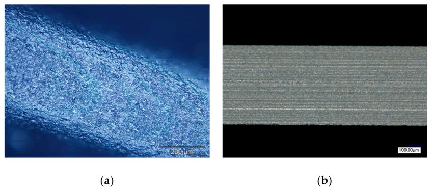
J. Manuf. Mater. Process. 2021, 5, 20                                                                                             2 of 12

                                        ultrasonic vibration-assisted micro-machining [12], and micromachining mechanics by
                                        considering chip thickness accumulation [13]. However, not much work has been done on
                                        grinding or/and machining of display glass substrates. The brittle nature of glass makes it
                                        very sensitive to tiny cracks, which can cause the display glass panels to break at stresses
                                        far below its theoretical strength [2].

                                        Table 1. Panel size of different generations of display glass substrates.

                                                   Generation                            Year                       Size (mm)
                                                         1                               1988                        300 × 400
                                                         2                               1993                        360 × 465
                                                         3                               1995                        550 × 650
                                                         4                               2000                        730 × 920
                                                         5                               2002                       1100 × 1300
                                                         6                               2003                       1500 × 1850
                                                         7                               2005                       1870 × 2200
                                                         8                               2008                       2200 × 2500
                                                         9                               2009                       2400 × 2800
                                                        10                               2010                       2880 × 3130
                                                       10.5                              2019                       2940 × 3370

                                             Display glass substrates are manufactured by the fusion process, where the molten
                                        glass is flowed over sides and drawn down to form a continuous flat piece of glass with
                                        very precise thickness controls, and then cut or scribed into the glass panel size. Edge
                                        cutting of display glass substrates is one of main sources for introducing cracks/defects
                                        and downgrading the material strength so that most glass panel failures initiate from
                                        an edge [2]. A vibration-assisted scribing technique of LCD glass substrate has been
                                        developed to automatically separate the glass substrate without the need of breaking
                                        process [14]. The formation of subsurface damage induced by grinding of LCD glass panels
                                        was investigated using two types of diamond wheels [15]. The chemo-mechanical grinding
                                        (CMG) process has been developed for the machining of quartz glass substrates to target
                                        a defect-free machining process [16]. More importantly, edge grinding is also one of the
                                        most efficient manufacturing processes for making display glass panels to remove the edge
                                        defects induced by the above-mentioned edge cutting process, of which the edge defects
                                        are replaced by multiple small flaws/cracks from the grinding process [15]. In this paper,
                                        edge grinding characteristics of display glass substrate will be systemically studied and
                                        analyzed in terms of theoretical analysis of ductile mode machining, grinding forces and
                                        torque, ground surface topography, and grinding wheel tool wear in order to understand
                                        the glass substrate grinding behavior and provide benefit to the industry and research
                                        communities.

                                        2. Theoretical Analysis
                                             When machining brittle materials, there is a brittle-to-ductile transition of machin-
                                        ing modes when continuously reducing the cutting depth down to the micron and/or
                                        nanometer scale, which is largely depended on workpiece material’s properties and its
                                        manufacturing processes [17]. According to the Griffith fracture mechanics [17,18], a critical
                                        depth-of-indentation or critical undeformed chip thickness at brittle-to-ductile transition
                                        region in machining of brittle materials can be predicted by
                                                                                                   2
                                                                                       E         KC
                                                                                dc = u                                               (1)
                                                                                       H         H

                                        where dc is the critical undeformed chip thickness or the critical depth of indentation, H
                                        is material hardness, E is Young’s modulus, and KC is material fracture toughness. In
                                        addition, u is the transition factor of the workpiece material from brittle mode machining
                                        to ductile mode machining, which is dominated by the workpiece material properties.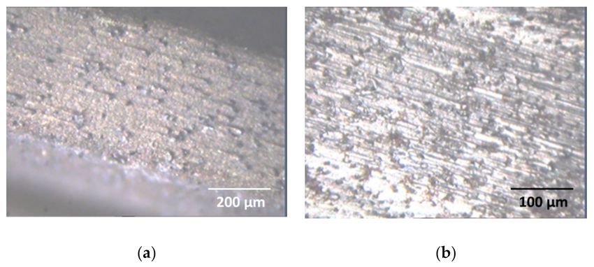
J. Manuf. Mater. Process. 2021, 5, 20                                                                                                3 of 12

                                              According to Equation (1), there is a critical value of undeformed chip thickness in
                                        machining of brittle materials, below which the chips will be formed under ductile mode
                                        machining. This critical value is a function of the brittle material’s hardness, Young’s
                                        modulus, and fracture toughness. The above theoretical description demonstrates that a
                                        critical depth of cut and an area of brittle-to-ductile transition exist during the machining of
                                        brittle materials, although the critical value may be varied and controlled by the workpiece
                                        inherent configuration and loading conditions.
                                              The workpiece material used in this study is display glass substrate NA35, and its
                                        material properties are listed in Table 2. Substituting the values of glass’s elastic modulus,
                                        hardness, and critical fracture toughness into Equation (1), as well as the value of transition
                                        factor from brittle mode to ductile mode u of 0.15 [17], we determined the theoretical critical
                                        depth of cut dc for ductile mode machining of the display glass substrate as 40 nm.

                                        Table 2. Material properties of glass substrate NA35.

                                                      Material Properties                                            Display Glass
                                                   Specific gravity (g/cm)3                                                2.49
                                                   Young’s modulus (GPa)                                                   70.9
                                                     Modulus of rigidity                                                   28.3
                                                 Modulus of volume elasticity                                              45.2
                                                    Knoop hardness (GPa)                                                   5.2
                                                Fracture toughness (MPa·m0.5 )                                              0.7
                                                        Poisson’s ratio                                                    0.24
                                                       Strain point (◦ C)                                                  661
                                                     Annealing point (◦ C)                                                 715
                                                     Softening point (◦ C)                                                 895
                                              Roughness (RMS, nm) 1 × 1 µm size                                           0.324
                                                    Refractive index (Nd)                                                 1.513
                                                   Dielectric constant (S/m)                                                4.7

                                             Moreover, for grinding, the maximum undeformed chip thickness for an individual
                                        grinding abrasive grit, hmax , can be calculated by the following equation [19]:
                                                                               "                           1/2 #1/2
                                                                                     3         vw        ae
                                                                      hmax =                                                            (2)
                                                                                   Ctanα       vs        ds

                                        where C is the density of active grinding points, α is the semi-induced angle of cross section
                                        for the undeformed chip, ds is the grinding wheel diameter, vw is workpiece feed rate, vs is
                                        the grinding wheel speed, and ae is the wheel depth of cut. Thus, when grinding of NA35
                                        glass with a given grinding condition, its maximum undeformed chip thickness hmax can
                                        be calculated by Equation (2) accordingly.

                                        3. Experiment Details
                                             Edge grinding experiments of display glass substrates were carried out on an Okamoto
                                        CNC (computer numerical control) high-speed grinder using a diameter of 250 mm resin-
                                        bound diamond wheel with the diamond abrasive mesh size of 500 (grit size ranging
                                        from 31 µm to 37 µm) with a diamond abrasive concentration rate of 75%. The grinding
                                        wheel was pre-balanced using a Sigma dynamic balancer at the different grinding speeds
                                        to be employed in the late experiments. High pressure water-based coolant and grinding
                                        conditions used for the tests are listed in Table 3. Workpiece size was 300 × 50 × 0.7 mm
                                        for the edge grinding tests. Figure 1 is a close view of the edge grinding experimental
                                        setup. A specially designed vise was used to clamp the display glass substrate with two
                                        pieces of rubber on each side of the clamping to protect the glass substrate.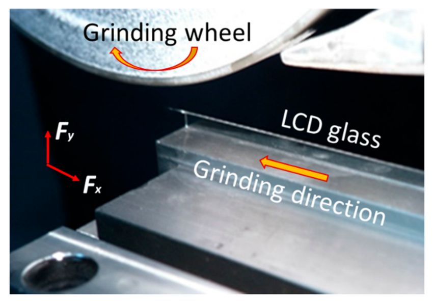
J. Manuf. Mater. Process. 2021, 5, 20                                                                                                 4 of 12

                                        Table 3. Edge grinding conditions used for glass substrates.

                                                      Grinding Parameters                               Grinding Conditions
                                                     Spindle speed (rpm)                            250, 500, 750, 1000, 2000, 3000
                                                     Feed rate (mm/min)                                       7000, 10,000
                                                     Grinding depth (mm)                                   0.1, 0.15, 0.2, 0.4
                                                     High-pressure coolant                                   Water-based

                                        Figure 1. Close view of the edge grinding experimental setup.

                                             Figure 2 shows the schematic diagram of the data acquisition system for edge grinding
                                        of display glass substrates, which was employed to collect the grinding forces and torque
                                        using 1 Kistler four-component rotary dynamometer and 1 Kistler three-component static
                                        dynamometer, as well as grinding wheel spindle current value using a current transducer.
                                        Grinding temperature was measured using a diameter of 0.5 mm thermocouple and a Pico
                                        recorder, as shown in Figure 3. Sand blasting was used to produce a half cylinder on a
                                        thickness of 0.7 mm glass substrate, and two pieces of such glass substrates were clamped
                                        together to form a blind hole so as to embed a diameter of 0.5 mm thermocouple inside,
                                        as shown in Figure 3a. Figure 3b shows the actual embedded thermocouples in glass
                                        substrates. Ground glass edge surface was examined using a Keyence optical microscope
                                        and a scanning electron microscope (SEM). Diamond grinding wheel wear was examined
                                        using an optical microscope and SEM.

                                        Figure 2. Data acquisition system for edge grinding of display glass substrates.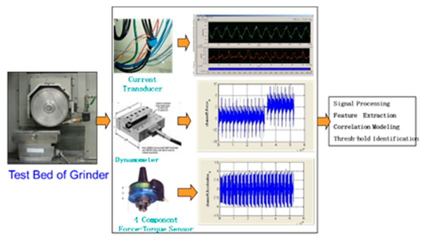
J. Manuf. Mater. Process. 2021, 5, 20                                                                                            5 of 12

                                        Figure 3. Experimental details of temperature measurement in edge grinding of glass substrates:
                                        (a) schematic illustration of embedded thermocouples; (b) actual embedded thermocouples in
                                        glass substrates.

                                        4. Experimental Results
                                             Edge grinding experiments were conducted and repeated to investigate its grinding
                                        performance through the plane grinding method using the diamond cut glass substrate
                                        NA35. Its edge grinding characteristics were examined and analyzed accordingly.

                                        4.1. Grinding Force and Torque
                                             Figure 4 shows an example of the measured grinding forces and spindle torque
                                        obtained in the plane grinding of glass substrate edges, where the grinding conditions
                                        used were grindings speed of 26.2 m/s (2000 rpm), feed rate of 10,000 mm/min, depth of
                                        cut of 0.15 mm, and high-pressure coolant. As the four-component Kistler dynamometer
                                        was mounted to the grinding spindle in the horizontal direction, which usually is mounted
                                        on a vertical milling spindle to measure machining forces and torque, the mass of the
                                        dynamometer together with the grinding wheel acted as a pre-loading. Thereafter, all the
                                        measured forces Fx and Fy had an initial value and the measured torque had an off-set
                                        value before the actual grinding in response to the pre-loading, as shown in Figure 4. As
                                        seen from Figure 4a,b, grinding force (Fy ) in the vertical direction was about 10 times larger
                                        than grinding force (Fx ) in the horizontal direction. It is clearly indicated that there was a
                                        very big compressive stress acting on the glass substrate workpiece, which was a potential
                                        source for glass substrate cracking and fracturing.
                                             Figure 5 shows the effects of grinding distance and spindle speed on the grinding force
                                        and torque obtained in the plane grinding of glass substrate edges, where the grinding
                                        conditions used were feed rate of 10,000 mm/min, depth of cut of 0.15 mm, and high-
                                        pressure coolant. Here, each grinding test was repeated three times and the presented
                                        grinding forces and torque were the average values of the three measurements. As seen
                                        from Figure 5a, grinding force (Fx ) in the horizontal direction was almost constant while
                                        grinding force (Fy ) in the vertical direction was trended to increase when increasing the
                                        grinding distance. As shown in Figure 5b, both grinding force (Fx ) in the horizontal
                                        direction and grinding force (Fy ) in the vertical direction were trended to decrease with the
                                        increase of grinding speed, while grinding torque was slightly increased with the increase
                                        of grinding speed, as shown in Figure 5c.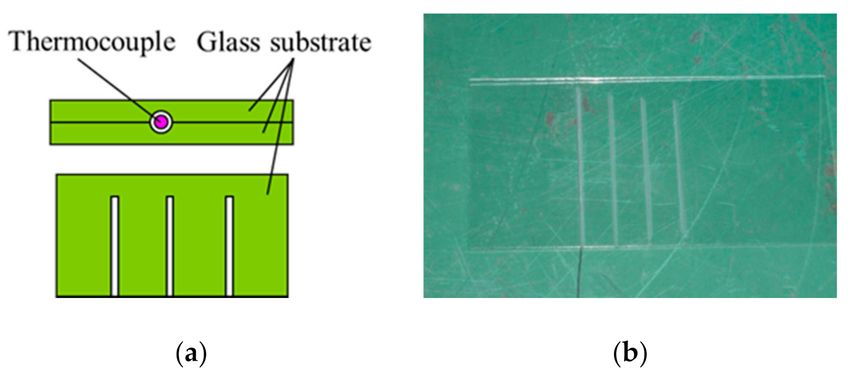
J. Manuf. Mater. Process. 2021, 5, 20                                                                                                 6 of 12

                                        Figure 4. Grinding forces and spindle torque measured in the plane grinding of glass substrate edges:
                                        (a) grinding force, Fx ; (b) grinding force, Fy ; (c) grinding spindle torque.

                                        Figure 5. Effects of grinding distance and speed on grinding force and torque: (a) grinding force vs.
                                        grinding distance; (b) grinding force vs. spindle speed; (c) grinding torque vs. grinding distance.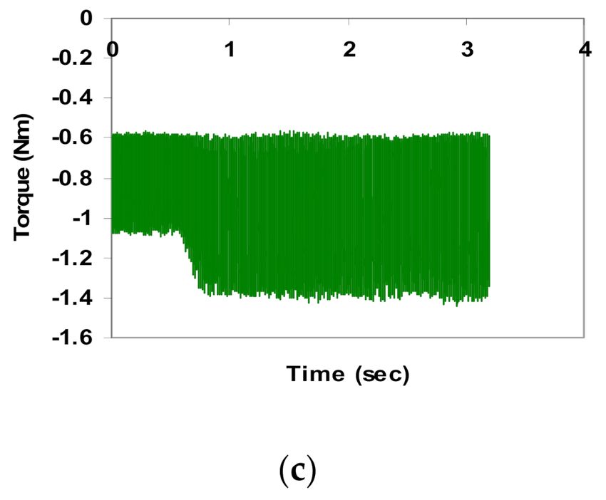
J. Manuf. Mater. Process. 2021, 5, 20                                                                                             7 of 12

                                        4.2. Grinding Temperature
                                             Grinding temperature was measured using a thermocouple embedded in glass sub-
                                        strate workpiece, where the grinding conditions used were grindings speed of 26.2 m/s
                                        (2000 rpm); feed rate of 7000 mm/min and 10,000 mm/min; depths of cuts of 0.1, 0.2, and
                                        0.4 mm. As seen from Figure 6a, the grinding temperature was slightly increased with the
                                        increase of grinding depth when applying high-pressure coolant, while the temperature
                                        increase was much faster when a higher feed rate was used. However, when grinding
                                        under drying condition, the grinding temperature was increased extremely fast with the
                                        increase of grinding depth, as shown in Figure 6b. Compared the temperature rising ob-
                                        tained under the two conditions, the grinding temperature obtained under dry conditions
                                        was one order higher than that obtained when applying high-pressure coolant. Moreover,
                                        the grinding temperature reached over 1100 ◦ C when grinding under dry conditions and
                                        with the grinding depth of 0.4 mm, of which the high grinding temperature may melt the
                                        grinding chips produced in the plane-grinding of glass substrate edges.%endparacol

                                        Figure 6. Grinding temperature measured in plane grinding of glass substrate edges: (a) grinding
                                        under high-pressure coolant; (b) grinding under dry conditions.

                                        4.3. Ground Surface Topography
                                              Ground surface topography was examined using an optical microscope and SEM, as
                                        shown in Figure 7, where the grinding conditions used were grinding speed of 26.2 m/s
                                        (2000 rpm), feed rate of 10,000 mm/min, depth of cut of 0.15 mm, and high-pressure
                                        coolant. Figure 7a is an overview of the ground glass edge topography, showing a very
                                        rough grinding surface generated. Figure 7b is a close view of the ground glass edge
                                        topography, showing that the ground surfaces were generated primarily by brittle fracture
                                        with a particle or chip adhered on the ground glass surface and the evidence of localized
                                        flow in the plane grinding of glass substrate edges. As seen from Figure 7c, a few small
                                        balls circled by redlines were found to be adhered to the ground glass surface, which is
                                        believed to be the melted or softened grinding chips/debris solidified by the high-pressure
                                        flush coolant under room temperature.
                                              In fact, those small balls adhered on the ground glass edge as shown in Figure 7c were
                                        the high potential sources causing the glass substrate cracking in the subsequent integrated
                                        circuit (IC) printing process, where a big temperature fluctuation was experienced. It will
                                        be extreme costly to stop the production line for cleaning if the ground glass substrate
                                        is cracked and broken on the line. Therefore, it is very important to control the grinding
                                        chips/debris flowing direction during the grinding of glass substrate edges, so as to
                                        illuminate those melted or softened grinding chips/debris adhered to the ground glass
                                        edge and non-ground glass panel surface.
J. Manuf. Mater. Process. 2021, 5, 20 8 of 12
Figure 7. Ground edge surface topography and defects: (a) overview of ground edge; (b) close view
of ground edge; (c) chips adhered on the ground edge; (d) defects on ground edge.
SEM observation of the defects produced on the ground glass substrate edge ty-
pography is shown in Figure 7d, where the marked white-line circles are cracks and
porosity produced, and the marked white line rectangle is the grinding streaks that are the
compression-induced abrasion marks [20]. Those cracks and porosity are the evidence of
brittle mode grinding of glass substrate, and those parallel grinding streaks are also the ev-
idence of ductile mode grinding behavior. Therefore, the grinding of glass substrate edges
is behaved as brittle mode grinding under the above-mentioned experimental conditions.
However, partial grinding of glass substrate edge was experienced under ductile mode
grinding. This agrees with the theoretical analysis in Section 2 that the grinding of glass
substrate edge was under brittle mode, and fractured surface was obtained when grinding
the glass substrate using the above-mentioned conditions.
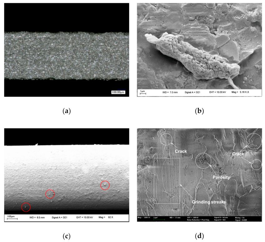
4.4. Diamond Wheel Wear
The diamond grinding wheel topography was examined before and after grinding
using an optical microscope and SEM, as shown in Figures 8 and 9. A fresh diamond-
grinding wheel is shown in Figure 8a, where the diamond grits were well protruded out
from the resin bonder. Figure 8b shows the used diamond grinding wheel topography
after grinding of 500 cycles (150 m), where some grooves with abrasive traces were found
on the diamond wheel surface, which was parallel to the grinding direction, indicating the
occurrence of a typical abrasion wear. These phenomena may be attributed to the soft resin
binder of the diamond wheel being abraded by the display glass substrate.
The wear patterns of the used grinding wheel are shown in Figure 9. A protruded
diamond grit is shown in Figure 9a on the used diamond wheel surface, where the grinding
direction is from right to left. It was found that the soft binder in the front of the diamond
grit was removed more than that behind the diamond grit, indicating that the diamond
grit protruded freshly. Figure 9b shows a worn diamond grit on the used diamond wheelJ. Manuf. Mater. Process. 2021, 5, 20 9 of 12
surface. It is clearly indicated that the soft binder was removed equally surrounding the
diamond grit and the diamond grit experienced the grit fracture during the grinding of
glass substrate. Figure 9c shows a pocket on the used diamond wheel surface, indicating a
pull-out of high protruding loosely held diamond grit.
Figure 8. Diamond grinding wheel surface topography before and after usage: (a) fresh grinding
wheel; (b) used grinding wheel.
Figure 9. Diamond grinding wheel wear patterns: (a) a protruded diamond grit; (b) a worn diamond
grit; (c) diamond grit pull out.
5. Discussion
In terms of plane-grinding glass substrate with a #500 resin-bound diamond wheel
with a diameter ds of 250 mm and the diamond abrasive concentration rate of 75%, using
feed rate vw of 10,000 mm/min, grindings speed of 26.2 m/s (2000 rpm), and depth ofJ. Manuf. Mater. Process. 2021, 5, 20 10 of 12
cut ae of 0.15 mm, thus here C is given by 40 and the semi-induced angle α is 60◦ [19].
Its maximum undeformed chip thickness for an individual grinding abrasive grit hmax
calculated using Equation (2) was 2.60 µm, which was much larger than the critical depth
of cut dc of 40 nm for ductile mode grinding of glass substrates. Both the theoretical
analysis and experimental results shown in Figure 7 clearly indicate that the edge grinding
of glass substrates using the above-mentioned grinding conditions was under brittle
mode grinding, while cracks were found on the ground surface of glass substrates. In
the production, when grinding with a formed resin-bound diamond wheel having the
same wheel diameter, grit size, and abrasive concentration rate but increasing the grinding
wheel speed vs to 3000 rpm, and reducing depth of cut ae to 0.1 mm, while other grinding
conditions remaining unchanged, we found the calculated maximum undeformed chip
thickness for an individual grinding abrasive grit hmax of 1.92 µm to be still greatly larger
than the critical depth of cut dc of 40 nm for ductile mode grinding of glass, which again
confirmed that fractured surfaces were generated in grinding of glass substrates with the
formed diamond wheel due to brittle mode grinding, as shown in Figure 10a.
Figure 10. Ground surfaces of glass substrate edges: (a) fractured surface obtained under the spindle
speed of 3000 rpm, feed rate of 7000 mm/min, and depth of cut of 0.1 mm; (b) smooth surface
obtained under the spindle speed of 6000 rpm, feed rate of 5 mm/min, and depth of cut of 0.05 mm.
When further increasing the grinding speed vs to 78.5 m/s (6000 rpm), reducing depth
of cut ae to 0.05 mm, and largely reducing feed rate to 5 mm/min for plane grinding, we
found the calculated maximum undeformed chip thickness for an individual grinding
abrasive grit hmax of 25.5 nm to be smaller than the critical depth of cut dc of 40 nm for
ductile mode grinding of glass substrates, which indicates that ductile mode grinding
and smooth surfaces could be achieved under this grinding condition. Observation of the
surface morphology of ground glass surfaces shown in Figure 10b is in agreement with the
above-mentioned material removal mechanism, of which the ground surface exhibited a
smooth appearance produced by ductile mode grinding of glass substrates. In addition,
there were some grinding marks on the ground surface showing the evidence of localized
flow, which were parallel to the grinding direction.
As shown in Figure 9b, some micro sharp edges were generated on the top of fractured
diamond grits during grinding of glass substrates, playing the roles as micro cutting edges
to perform the material removal [21,22]. Thus, partial grinding of glass substrate edge
experienced ductile mode grinding behavior was attributed to and contributed by those
micro cutting edges, which can be seen as a self-explanation of partial grinding performed
under ductile mode, although the overall grinding behavior was under brittle mode.
Edge grinding is commonly used in the production of display glass panels to round
the sharp edges and remove cutting defects of the glass edges. The strength of a display
glass panel is actually a measure of the surface defects’ size and number in the glass panel.
The larger the defects, the weaker the glass panel will be [2]. Although ductile modeJ. Manuf. Mater. Process. 2021, 5, 20 11 of 12
grinding can be achieved under certain conditions, as shown in Figure 10b, the feed rate
of 5 mm/min used is extremely slow. As a great penalty, the grinding process will be
the bottleneck of the whole production and significantly low down the productivity line,
which is definitely not acceptable by the industry. In fact, it is unavoidable to experience
microcrack propagation and subsurface damages even after fine grinding of brittle materials
including glass substrates [7,23–25]. Therefore, the polishing process is employed as a
necessary subsequent manufacturing process to totally remove the grinding defects and
subsurface damages for the production of display glass panels.
6. Conclusions
Theoretical analysis and experimental study on edge grinding of display glass sub-
strate were conducted to investigate its grinding characteristics using a resin-bound dia-
mond wheel under different grinding conditions. Some findings are summarized below:
• Grinding force (Fy ) in the vertical direction obtained in the test conditions was much
larger than grinding force (Fx ) in the horizontal direction, causing a large compressive
stress acting on the grinding glass edge.
• Grinding force (Fx ) was almost constant, while grinding force (Fy ) tended to increase
when increasing the grinding distance up to 200 m. Grinding torque was slightly
increased with the increase of grinding speed.
• Grinding temperature rising was slightly increased with the increase of grinding
depth from 0.1 to 0.4 mm when applying high-pressure coolant, and it was increased
much faster when a higher feed rate was used. Grinding temperature was measured
as over 1100 ◦ C under dry grinding.
• Ground surface topography analysis indicated that the grinding of glass substrate edge
in the test conditions was performed under brittle mode machining, and fractured
surface was obtained in the production.
• It was found that grinding of glass substrate edge was performed partially under
ductile mode machining in the experimental conditions, which can be attributed to
and contributed by those micro cutting edges generated by the fractured diamond grit
on the grinding wheel surface.
• Ductile mode machining of glass substrate and smooth surface can be achieved under
certain conditions when the critical undeformed chip thickness was less than 40 nm.
However, the productivity for ductile mode machining conditions is extremely low,
and thus subsequent polishing process is essential for display glass panel production.
Author Contributions: Conceptualization, K.L. and H.W.; methodology, K.L.; formal analysis,
D.W.K.N. and R.H.; resources, R.H.; data curation, H.W.; writing—original draft preparation,
D.W.K.N. and R.H.; writing—review and editing, K.L.; supervision, K.L. All authors have read
and agreed to the published version of the manuscript.
Funding: This research received no external funding.
Data Availability Statement: Not applicable.
Acknowledgments: The authors would like to thank Ng Seow Tong and Shaw Kah Chuan Sean for
help on conducting experiments.
Conflicts of Interest: The authors declare no conflict of interest.
References
1. Huet, R.; Ming, W. LCD display strength: Why edge preparation matters. In Proceedings of the IEEE International Conference on
Portable Information Devices, Orlando, FL, USA, 25–29 May 2007.
2. Minami, H.; Mori, J.; Iwai, S.; Moriya, H.; Watanabe, N. Manufacturing and inspection equipment for efficient production of large
LCDs. Hitachi Rev. 2011, 60, 228–232.
3. Liu, K.; Wang, H.; Zhang, X.Q. Ductile mode cutting of glass. In Ductile Mode Cutting of Brittle Materials; Springer Nature:
Singapore, 2020; pp. 135–148.J. Manuf. Mater. Process. 2021, 5, 20 12 of 12
4. Antwi, E.K.; Liu, K.; Wang, H. A review on ductile mode cutting of brittle materials. Front. Mech. Eng. 2018, 13, 251–263.
[CrossRef]
5. Liu, K.; Li, X.P.; Liang, S.Y.; Liu, X.D. Nanometer scale ductile mode cutting of soda-lime glass. J. Manuf. Proc. 2005, 7, 95–101.
[CrossRef]
6. Huerta, M.; Malkin, S. Grinding of glass: The mechanics of the process. ASME T J. Eng. Ind. 1976, 98, 459–467. [CrossRef]
7. Huerta, M.; Malkin, S. Grinding of glass: Surface strength and fracture strength. ASME T J. Eng. Ind. 1976, 98, 468–473. [CrossRef]
8. Fang, F.Z.; Chen, L.J. Ultra-precision cutting for ZKN7 glass. Ann. CIRP 2000, 49, 17–20. [CrossRef]
9. Fang, F.Z.; Xu, F.F. Recent advances in micro/nano-cutting: Effect of tool edge and material properties. Nanomanuf. Metrol. 2018,
1, 4–31. [CrossRef]
10. Zhou, M.; Wang, X.J.; Ngoi, B.K. Brittle ductile transition in the diamond cutting of glasses with the aid of ultrasonic vibration. J.
Mater. Proc. Tech. 2002, 121, 243–251. [CrossRef]
11. Moriwaki, T.; Shmoto, E.; Inoue, K. Ultraprecision ductile cutting of glass by applying ultrasonic vibration. Ann. CIRP 1992, 41,
141–144. [CrossRef]
12. Arefin, S.; Zhang, X.Q.; Kumar, A.S.; Liu, K.; Neo, W.K. An analytical model for determining the shear angle in 1D vibration-
assisted micro machining. Nanomanuf. Metrol. 2019, 2, 199–214. [CrossRef]
13. Wojciechowski, S.; Matuszak, M.; Powałka, B.; Madajewski, M.; Maruda, R.W.; Krolczyk, G.M. Prediction of cutting forces during
micro end milling considering chip thickness accumulation. I J. Mach. Tool Manuf. 2019, 147, 103466. [CrossRef]
14. Liao, Y.S.; Yang, G.M.; Hsu, Y.S. Vibration assisted scribing process on LCD glass substrate. I J. Mach. Tool Manuf. 2010, 50,
532–537. [CrossRef]
15. Zhong, Z.W.; Tian, Y.B.; Xie, T.G. Investigation of subsurface damage of ground glass edges. I J. Adv. Manuf. Tech. 2016, 87,
3261–3269. [CrossRef]
16. Zhou, L.; Shiina, T.; Qiu, Z.; Shimizu, J.; Yamamoto, T.; Tashiro, T. Research on chemo-mechanical grinding of large size quartz
glass substrate. Prec. Eng. 2009, 33, 499–504. [CrossRef]
17. Bifano, T.G.; Dow, T.A.; Scattergood, R.O. Ductile-regime grinding: A new technology for machining brittle materials. ASME T J.
Eng. Ind. 1991, 113, 184–189. [CrossRef]
18. Ewalds, H.L.; Wanhill, R.J.H. Fracture Mechanics; Edward Arnold: London, UK, 1986; pp. 15–68.
19. Malkin, S.; Guo, C.S. Grinding Technology: Theory and Applications of Machining with Abrasives; Industrial Press Inc.: New York, NY,
USA, 2008; pp. 43–79.
20. Liu, K.; Wang, H.; Zhang, X.Q. Ductile mode cutting mechanisms. In Ductile Mode Cutting of Brittle Materials; Springer Nature:
Singapore, 2020; pp. 17–37.
21. Fang, F.Z.; Liu, K.; Kurfess, T.R.; Lim, G.C. Tool-based micro machining and applications in MEMS. In MEMS/NEMS Handbook:
Techniques and Applications; Leondes, C.T., Ed.; Springer: Boston, MA, USA, 2006; Volume 3, pp. 678–840.
22. O’Hara, J.; Fang, F.Z. Advances in micro cutting tool design and fabrication. I J. Extrem. Manuf. 2019, 1, 032003. [CrossRef]
23. Liu, K.; Zuo, D.W.; Li, X.P.; Rahman, M. Nanometric ductile cutting characteristics of silicon wafer using single crystal diamond
tools. J. Vacu. Sci. Tech. B 2009, 27, 1361–1366. [CrossRef]
24. Khatri1, N.; Barkachary, B.M.; Muneeswaran, B.; Al-Sayegh, R.; Luo, X.C.; Goel, S. Surface defects incorporated diamond
machining of silicon. I J. Extrem. Manuf. 2020, 2, 045102. [CrossRef]
25. Liu, K.; Li, X.P.; Liang, S.Y. The mechanism of ductile chip formation in cutting of brittle materials. I J. Adv. Manuf. Tech. 2007, 33,
875–884. [CrossRef]You can also read