Enerlin'X FDM128 Ethernet Display for Eight Devices User Guide 01/2019 - Schneider Electric
←
→
Page content transcription
If your browser does not render page correctly, please read the page content below
Enerlin'X FDM128

                                       DOCA0037EN-07 01/2019

                Enerlin'X FDM128
                Ethernet Display for Eight Devices
                User Guide
                01/2019
DOCA0037EN-07

                www.schneider-electric.com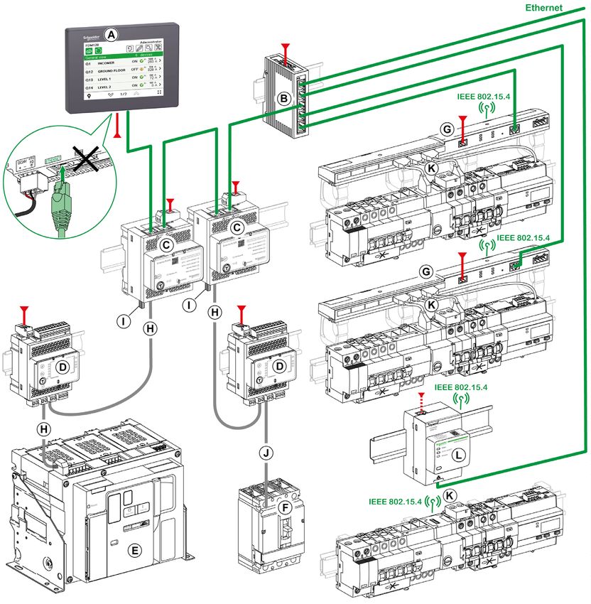
The information provided in this documentation contains general descriptions and/or technical character-
    istics of the performance of the products contained herein. This documentation is not intended as a
    substitute for and is not to be used for determining suitability or reliability of these products for specific user
    applications. It is the duty of any such user or integrator to perform the appropriate and complete risk
    analysis, evaluation and testing of the products with respect to the relevant specific application or use
    thereof. Neither Schneider Electric nor any of its affiliates or subsidiaries shall be responsible or liable for
    misuse of the information contained herein. If you have any suggestions for improvements or amendments
    or have found errors in this publication, please notify us.
    You agree not to reproduce, other than for your own personal, noncommercial use, all or part of this
    document on any medium whatsoever without permission of Schneider Electric, given in writing. You also
    agree not to establish any hypertext links to this document or its content. Schneider Electric does not grant
    any right or license for the personal and noncommercial use of the document or its content, except for a
    non-exclusive license to consult it on an "as is" basis, at your own risk. All other rights are reserved.
    All pertinent state, regional, and local safety regulations must be observed when installing and using this
    product. For reasons of safety and to help ensure compliance with documented system data, only the
    manufacturer should perform repairs to components.
    When devices are used for applications with technical safety requirements, the relevant instructions must
    be followed.
    Failure to use Schneider Electric software or approved software with our hardware products may result in
    injury, harm, or improper operating results.
    Failure to observe this information can result in injury or equipment damage.
    © 2019 Schneider Electric. All rights reserved.

2                                                                                                  DOCA0037EN-07 01/2019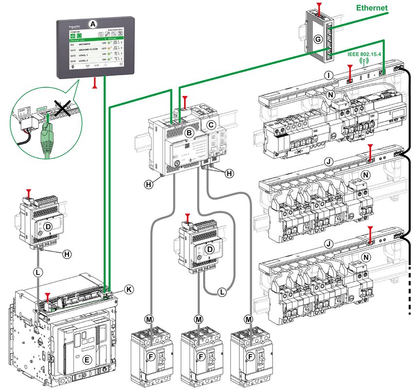
Table of Contents

                     Safety Information. . . . . . . . . . . . . . . . . . . . . . . . . . . . . . . . . . . . . . . . . . . .                                            5
                     About the Book . . . . . . . . . . . . . . . . . . . . . . . . . . . . . . . . . . . . . . . . . . . . . .                                           7
           Chapter 1 Introduction . . . . . . . . . . . . . . . . . . . . . . . . . . . . . . . . . . . . . . . . . . . . . . . . .                                      11
                           Overview . . . . . . . . . . . . . . . . . . . . . . . . . . . . . . . . . . . . . . . . . . . . . . . . . . . . . . . . . . . . . . . .      12
                           Architecture Examples. . . . . . . . . . . . . . . . . . . . . . . . . . . . . . . . . . . . . . . . . . . . . . . . . . . . . .              15
                           Recommendations. . . . . . . . . . . . . . . . . . . . . . . . . . . . . . . . . . . . . . . . . . . . . . . . . . . . . . . . .              23
                           Certifications and Standards . . . . . . . . . . . . . . . . . . . . . . . . . . . . . . . . . . . . . . . . . . . . . . . . .                24
                           General Specifications. . . . . . . . . . . . . . . . . . . . . . . . . . . . . . . . . . . . . . . . . . . . . . . . . . . . . .             25
                           Functional Specifications . . . . . . . . . . . . . . . . . . . . . . . . . . . . . . . . . . . . . . . . . . . . . . . . . . .               27
                           Interface Specifications . . . . . . . . . . . . . . . . . . . . . . . . . . . . . . . . . . . . . . . . . . . . . . . . . . . . .            28
           Chapter 2 Presentation . . . . . . . . . . . . . . . . . . . . . . . . . . . . . . . . . . . . . . . . . . . . . . . .                                        29
                           Screen . . . . . . . . . . . . . . . . . . . . . . . . . . . . . . . . . . . . . . . . . . . . . . . . . . . . . . . . . . . . . . . . . .    30
                           Menu Structure . . . . . . . . . . . . . . . . . . . . . . . . . . . . . . . . . . . . . . . . . . . . . . . . . . . . . . . . . . .          32
                           Browsing . . . . . . . . . . . . . . . . . . . . . . . . . . . . . . . . . . . . . . . . . . . . . . . . . . . . . . . . . . . . . . . .      33
           Chapter 3 Configuration . . . . . . . . . . . . . . . . . . . . . . . . . . . . . . . . . . . . . . . . . . . . . . .                                         35
                           Prerequisites . . . . . . . . . . . . . . . . . . . . . . . . . . . . . . . . . . . . . . . . . . . . . . . . . . . . . . . . . . . . .       36
                           Setting Wizard . . . . . . . . . . . . . . . . . . . . . . . . . . . . . . . . . . . . . . . . . . . . . . . . . . . . . . . . . . . .        37
                           Settings During Operation . . . . . . . . . . . . . . . . . . . . . . . . . . . . . . . . . . . . . . . . . . . . . . . . . . .               40
           Chapter 4 Operation . . . . . . . . . . . . . . . . . . . . . . . . . . . . . . . . . . . . . . . . . . . . . . . . . .                                       43
                           Logins and Passwords . . . . . . . . . . . . . . . . . . . . . . . . . . . . . . . . . . . . . . . . . . . . . . . . . . . . .                44
                           General View . . . . . . . . . . . . . . . . . . . . . . . . . . . . . . . . . . . . . . . . . . . . . . . . . . . . . . . . . . . . .        46
                           Real-Time Alarms . . . . . . . . . . . . . . . . . . . . . . . . . . . . . . . . . . . . . . . . . . . . . . . . . . . . . . . . .            49
                           Device View for Circuit Breakers and Switch-Disconnectors . . . . . . . . . . . . . . . . . . . . . . . .                                     51
                           Device View for Devices Connected to the Acti9 Smartlink . . . . . . . . . . . . . . . . . . . . . . . . .                                    55
           Chapter 5 Update and Maintenance . . . . . . . . . . . . . . . . . . . . . . . . . . . . . . . . . . . . . .                                                  59
                           Firmware Update . . . . . . . . . . . . . . . . . . . . . . . . . . . . . . . . . . . . . . . . . . . . . . . . . . . . . . . . . .           60
                           Adding, Removing, and Replacing Devices . . . . . . . . . . . . . . . . . . . . . . . . . . . . . . . . . . . . .                             62
                           Regular Cleaning. . . . . . . . . . . . . . . . . . . . . . . . . . . . . . . . . . . . . . . . . . . . . . . . . . . . . . . . . .           63
                           Troubleshooting Checklists . . . . . . . . . . . . . . . . . . . . . . . . . . . . . . . . . . . . . . . . . . . . . . . . . .                64
                           Protecting the Environment . . . . . . . . . . . . . . . . . . . . . . . . . . . . . . . . . . . . . . . . . . . . . . . . . .                65
       Appendices           .....................................................                                                                                        67
        Appendix A FDM128 Icons . . . . . . . . . . . . . . . . . . . . . . . . . . . . . . . . . . . . . . . . . . . . . .                                              69
                           Icon List . . . . . . . . . . . . . . . . . . . . . . . . . . . . . . . . . . . . . . . . . . . . . . . . . . . . . . . . . . . . . . . . .   69
        Appendix B Glossary of Acronyms. . . . . . . . . . . . . . . . . . . . . . . . . . . . . . . . . . . . . . . . .                                                 73
                           Acronym . . . . . . . . . . . . . . . . . . . . . . . . . . . . . . . . . . . . . . . . . . . . . . . . . . . . . . . . . . . . . . . .       73

DOCA0037EN-07 01/2019                                                                                                                                                     3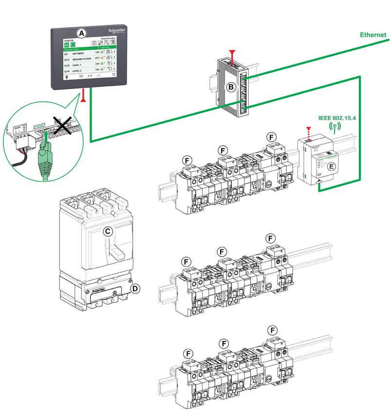
4 DOCA0037EN-07 01/2019
Safety Information

Important Information

NOTICE
                        Read these instructions carefully, and look at the equipment to become familiar with the device before
                        trying to install, operate, service, or maintain it. The following special messages may appear throughout
                        this documentation or on the equipment to warn of potential hazards or to call attention to information that
                        clarifies or simplifies a procedure.

PLEASE NOTE
                        Electrical equipment should be installed, operated, serviced, and maintained only by qualified personnel.
                        No responsibility is assumed by Schneider Electric for any consequences arising out of the use of this
                        material.
                        A qualified person is one who has skills and knowledge related to the construction and operation of
                        electrical equipment and its installation, and has received safety training to recognize and avoid the
                        hazards involved.

FCC Notice
                        This equipment has been tested and found to comply with the limits for a Class A digital device, pursuant
                        to part 15 of the FCC Rules. These limits are designated to provide reasonable protection against harmful
                        interference when the equipment is operated in a commercial environment. This equipment generates,
                        uses, and can radiate radio frequency energy and, if not installed and used in accordance with the
                        instruction manual, may cause harmful interference to radio communications. Operation of this equipment
                        in a residential area is likely to cause harmful interference in which case the user will be required to correct
                        the interference at this own expense.

DOCA0037EN-07 01/2019                                                                                                                 5
6 DOCA0037EN-07 01/2019
About the Book
At a Glance
Document Scope
This guide describes how to use Enerlin'X™ the FDM128 Ethernet display for eight devices, installed in an
Ethernet network, to monitor and control the following devices:
Circuit breakers equipped with communicating Micrologic™ trip units, such as:
Masterpact™ MTZ circuit breakers
Masterpact™ NT/NW circuit breakers
Compact™ NS circuit breakers
Compact™ NSX circuit breakers
PowerPact™ P- and R-frame circuit breakers
PowerPact™ H-, J-, and L-frame circuit breakers
Swith-disconnectors such as:
Masterpact NT HA switch-disconnectors
Masterpact NW NA/HA/HA10/HF switch-disconnectors
Compact NS NA switch-disconnectors
Compact NSX NA switch-disconnectors
Acti9 Smartlink™ devices, such as:
Acti9 Smartlink SI B
Acti9 Smartlink SI D
Acti9 Smartlink Modbus devices
PowerTag™ devices such as:
PowerTag Link
PowerTag Link HD
NOTE: The Acti9 Smartlink product range is not available in the following countries: United States,
Canada, Mexico. Consult the catalog for the list of products available in your country.
Validity Note
This documentation is valid for all FDM128 Ethernet display for eight devices.
The information contained in this document is likely to be updated at any time. Schneider Electric strongly
recommends that you have the most recent and up-to-date version available on www.schneider-
electric.com/docs.
The technical characteristics of the devices described in the present document also appear online. To
access the information online:
Step Action
1 Go to the Schneider Electric home page www.schneider-electric.com.
2 In the Search box type the reference of a product or the name of a product range.
Do not include blank spaces in the reference or product range.
To get information on grouping similar modules, use asterisks (*).
3 If you entered a reference, go to the Product Datasheets search results and click on the
reference that interests you.
If you entered the name of a product range, go to the Product Ranges search results and click
on the product range that interests you.
4 If more than one reference appears in the Products search results, click on the reference that
interests you.
5 Depending on the size of your screen, you may need to scroll down to see the data sheet.
6 To save or print a data sheet as a .pdf file, click Download XXX product datasheet.
The characteristics that are presented in the present document should be the same as those character-
istics that appear online. In line with our policy of constant improvement, we may revise content over time
to improve clarity and accuracy. If you see a difference between the document and online information, use
the online information as your reference.
DOCA0037EN-07 01/2019 7
Related Documents for IEC Devices

                   Title of Documentation                                                                 Reference Number
                   Enerlin’X FDM128 - Ethernet Display for Eight Devices - Instruction Sheet              HRB45777
                   Enerlin'X FDM128 - Ethernet Display for Eight Devices - Firmware Release Note          DOCA0151EN
                   Enerlin’X IFM - Modbus-SL Interface for One Circuit Breaker - Instruction Sheet        NVE85393
                   Enerlin’X IFE - Ethernet Interface for One Circuit Breaker - Instruction Sheet         QGH13473
                   Enerlin’X IFE - Ethernet Interface for One Circuit Breaker - User Guide (IEC version) DOCA0142EN
                                                                                                          DOCA0142ES
                                                                                                          DOCA0142FR
                                                                                                          DOCA0142ZH
                   Enerlin’X IFE - Ethernet Switchboard Server - User Guide (IEC version)                 DOCA0084EN
                                                                                                          DOCA0084ES
                                                                                                          DOCA0084FR
                                                                                                          DOCA0084ZH
                   Enerlin’X EIFE - Embedded Ethernet Interface for One Masterpact MTZ Drawout            NVE23550
                   Circuit Breaker - Instruction Sheet
                   Enerlin’X EIFE - Embedded Ethernet Interface for One Masterpact MTZ Drawout            DOCA0106EN
                   Circuit Breaker - User Guide                                                           DOCA0106ES
                                                                                                          DOCA0106FR
                                                                                                          DOCA0106ZH
                   Enerlin’X IO - Input/Output Application Module for One Circuit Breaker - Instruction   HRB49217
                   Sheet
                   Enerlin’X IO - Input/Output Application Module for One Circuit Breaker - User Guide    DOCA0055EN
                   (IEC version)                                                                          DOCA0055ES
                                                                                                          DOCA0055FR
                                                                                                          DOCA0055ZH
                   BCM ULP Circuit Breaker Communication Module - Installation Manual                     EAV36080 (EN, ES, FR)
                   Acti9 Smartlink Modbus Communication System - User Manual                              DOCA0004EN
                                                                                                          DOCA0004DE
                                                                                                          DOCA0004ES
                                                                                                          DOCA0004FR
                                                                                                          DOCA0004IT
                                                                                                          DOCA0004PT
                   Acti9 Smartlink Ethernet Communication System - User Manual                            DOCA0073EN
                                                                                                          DOCA0073DE
                                                                                                          DOCA0073ES
                                                                                                          DOCA0073FR
                                                                                                          DOCA0073IT
                                                                                                          DOCA0073PT
                   Acti9 Smartlink SI B Communication System - User Manual                                DOCA0123EN
                                                                                                          DOCA0123FR
                                                                                                          DOCA0123DE
                                                                                                          DOCA0123ES
                                                                                                          DOCA0123IT
                   Acti9 Smartlink SI D Communication System - User Manual                                DOCA0115EN
                                                                                                          DOCA0115FR
                                                                                                          DOCA0115DE
                                                                                                          DOCA0115ES
                                                                                                          DOCA0115IT
                   EGX300 PowerLogic™ Ethernet Gateway - User Guide                                       63230-319-216 (EN, ES, FR)
                   Micrologic 5/6/7 Trip Units for Compact NSX Circuit Breakers - User Guide              DOCA0141EN
                                                                                                          DOCA0141ES
                                                                                                          DOCA0141FR
                                                                                                          DOCA0141ZH
                   Compact NSX Modbus Communication Guide                                                 DOCA0091EN
                                                                                                          DOCA0091ES
                                                                                                          DOCA0091FR
                                                                                                          DOCA0091ZH
                   Micrologic A/E Trip Units for Masterpact NT/NW Circuit Breakers - User Guide           04443724AA (EN)
                                                                                                          EAV16735 (ES)
                                                                                                          04443723AA (FR)

8                                                                                                                  DOCA0037EN-07 01/2019
Title of Documentation Reference Number
Micrologic P Trip Units for Masterpact NT/NW Circuit Breakers - User Guide 04443726AA (EN)
EAV16736 (ES)
04443725AA (FR)
Micrologic H Trip Units for Masterpact NT/NW Circuit Breakers - User Guide 04443728AA (EN)
EAV16737 (ES)
04443727AA (FR)
Masterpact NT/NW, Compact NS Modbus Communication Guide DOCA0054EN
DOCA0054ES
DOCA0054FR
DOCA0054ZH
Masterpact MTZ1 Circuit Breakers and Switch-Disconnectors - User Guide DOCA0100EN
DOCA0100ES
DOCA0100FR
DOCA0100ZH
Masterpact MTZ2/MTZ3 Circuit Breakers and Switch-Disconnectors - User Guide DOCA0101EN
DOCA0101ES
DOCA0101FR
DOCA0101ZH
Micrologic X Control Unit for Masterpact MTZ Circuit Breakers - User Guide DOCA0102EN
DOCA0102ES
DOCA0102FR
DOCA0102ZH
Masterpact MTZ Modbus Communication Guide DOCA0105EN
DOCA0105ES
DOCA0105FR
DOCA0105ZH
ULP System for Compact and Masterpact Circuit Breakers - User Guide DOCA0093EN
DOCA0093ES
DOCA0093FR
DOCA0093ZH
TCSEGWB13FA0 - Portable Battery Powered Wi-Fi Access Point - Instruction Sheet NHA24030
You can download these technical publications and other technical information from our website at
https://www.schneider-electric.com/en/download
Related Documents for UL/ANSI Devices
Title of Documentation Reference Number
Enerlin’X FDM128 - Ethernet Display for Eight Devices - Instruction Sheet HRB45777
Enerlin'X FDM128 - Ethernet Display for Eight Devices - Firmware Release Note DOCA0151EN
Enerlin’X IFM - Modbus-SL Interface for One Circuit Breaker - Instruction Sheet NVE85393
Enerlin’X IFE - Ethernet Interface for One Circuit Breaker - Instruction Sheet QGH13473
Enerlin’X IFE - Ethernet Interface for One Circuit Breaker - User Guide (UL 0602IB1801EN
version) 0602IB1801FR
0602IB1801ES
0602IB1801ZH
Enerlin’X IFE - Ethernet Switchboard Server - User Guide (UL version) 1040IB1401 (EN)
1040IB1402 (ES)
1040IB1403 (FR)
1040IB1404 (ZH)
Enerlin’X EIFE - Embedded Ethernet Interface for One Masterpact MTZ NVE23550
Drawout Circuit Breaker - Instruction Sheet
Enerlin’X EIFE - Embedded Ethernet Interface for One Masterpact MTZ DOCA0106EN
Drawout Circuit Breaker - User Guide DOCA0106ES
DOCA0106FR
DOCA0106ZH
Enerlin’X IO - Input/Output Application Module for One Circuit Breaker - HRB49217
Instruction Sheet
DOCA0037EN-07 01/2019 9Title of Documentation Reference Number
Enerlin’X IO - Input/Output Application Module for One Circuit Breaker - User 0613IB1317 (EN)
Guide (UL version) 0613IB1318 (ES)
0613IB1319 (FR)
0613IB1320 (ZH)
BCM ULP Circuit Breaker Communication Module - Installation Manual EAV36080 (EN, ES, FR)
EGX300 PowerLogic™ Ethernet Gateway - User Guide 63230-319-216 (EN, ES, FR)
Micrologic 5 and 6 Trip Units for PowerPact H-, J-, and L- Frame Circuit Breakers 48940-312 (EN, ES, FR)
- User Guide
PowerPact H-, J-, and L- Frame Circuit Breakers Modbus Communication Guide 0611IB1302 (EN)
0611IB1303 (ES)
0611IB1304 (FR)
0611IB1305 (ZH)
Micrologic 2.0A, 3.0A, 5.0A, and 6.0A Trip Units - Instruction Bulletin 48049-136 (EN, ES, FR)
Micrologic 5.0P and 6.0P Trip Units - Instruction Bulletin 48049-137 (EN, ES, FR)
Micrologic 5.0H and 6.0H Trip Units - Instruction Bulletin 48049-330 (EN, ES, FR)
Masterpact NT/NW, PowerPact P- and R-Frame Modbus Communication Guide 0613IB1313 (EN)
0613IB1314 (ES)
0613IB1315 (FR)
0613IB1316 (ZH)
Micrologic X Control Unit for Masterpact MTZ Circuit Breakers - User Guide DOCA0102EN
DOCA0102ES
DOCA0102FR
DOCA0102ZH
Masterpact MTZ Modbus Communication Guide DOCA0105EN
DOCA0105ES
DOCA0105FR
DOCA0105ZH
ULP System for PowerPact and Masterpact Circuit Breakers - User Guide 0602IB1503 (EN)
0602IB1504 (ES)
0602IB1505 (FR)
0602IB1506 (ZH)
TCSEGWB13FA0 - Portable Battery Powered Wi-Fi Access Point - Instruction NHA24030
Sheet
You can download these technical publications and other technical information from our website at
https://www.schneider-electric.com/en/download
Trademark Notice
All trademarks are owned by Schneider Electric Industries SAS or its affiliated companies.
10 DOCA0037EN-07 01/2019Enerlin'X FDM128
Introduction
DOCA0037EN-07 01/2019
Chapter 1
Introduction
Introduction
What Is in This Chapter?
This chapter contains the following topics:
Topic Page
Overview 12
Architecture Examples 15
Recommendations 23
Certifications and Standards 24
General Specifications 25
Functional Specifications 27
Interface Specifications 28
DOCA0037EN-07 01/2019 11Introduction
Overview
Presentation
The FDM128 Ethernet display for eight devices is a 1-to-8 human machine interface (HMI). The main
component is a 5.7-inch touch screen.
An FDM128 display can be connected to devices via an Ethernet interface by using:
One or more Ethernet gateways (IFE server, Link150, PowerLogic EGX300 and EGX100 Ethernet,
Acti9 Smartlink SI B, Acti9 Smartlink SI D, or Acti9 Smartlink Ethernet gateways).
One or more third-party Ethernet gateways that possess the appropriate characteristics.
Each type of connection is described further in this section.
The FDM128 display can monitor and control up to eight devices. The information displayed includes
measurements, alarms, and operating assistance data.
For ease of installation, a device discovery function is embedded in the FDM128 display.
Number and Nature of Connected Devices
Up to eight devices from the following list can be monitored simultaneously:
Masterpact MTZ circuit breakers
Masterpact NT/NW circuit breakers or switch-disconnectors
Compact NS 1600b-3200 circuit breakers or switch-disconnectors
Compact NS 630b-1600 circuit breakers or switch-disconnectors
PowerPact P- and R-frame circuit breakers
Compact NSX circuit breakers or switch-disconnectors
PowerPact H-, J-, and L-frame circuit breakers
Acti9 Smartlink SI B
Acti9 Smartlink SI D
Acti9 Smartlink Modbus
PowerTag Link
PowerTag Link HD
Monitored Devices Through Acti9 Smartlink SI B
When an Acti9 Smartlink SI B is connected to the FDM128 display, the status of the devices connected
through the Acti9 Smartlink SI B can be viewed on the FDM128 display.
The status of the following devices can be viewed on the FDM128 display:
Acti9 iOF+SD24 and OF+SD24 indication auxiliaries
Acti9 OF24 indication auxiliaries
Acti9 SD24 indication auxiliaries
Acti9 iACT24 and iATL24 auxiliaries for contactors and impulse relays in the Acti9 range
Acti9 RCA iC60 remote control module with Ti24 interface
Acti9 Reflex iC60 integrated control circuit breaker with Ti24 interface
Acti9 PowerTag energy sensors, which are directly mounted on a Acti9 circuit breaker and communicate
with the Acti9 Smartlink SI B through wireless communication. Refer to the Component Part Numbers
for the list of Acti9 PowerTag energy sensors (see page 21).
PowerTag NSX energy sensors, which are directly mounted on a Compact NSX circuit breaker and
communicate with the Acti9 Smartlink SI B through wireless communication. Refer to the Component
Part Numbers for the list of PowerTag NSX energy sensors (see page 21).
iEM2000T, iEM3110, iEM3155, iEM3210, and iEM3255 energy meters
Compact NSX OF+SD indication auxiliaries
NOTE: The Acti9 Smartlink product range is not available in the following countries: United States,
Canada, Mexico. Consult the catalog for the list of products available in your country.
12 DOCA0037EN-07 01/2019Introduction
Monitored Devices Through Acti9 Smartlink SI D, PowerTag Link, or PowerTag Link HD
When an Acti9 Smartlink SI D, PowerTag Link, or PowerTag Link HD is connected to the FDM128 display,
the status of the devices connected through the Acti9 Smartlink SI D, PowerTag Link, or PowerTag Link
HD can be viewed on the FDM128 display.
The status of the following devices can be viewed on the FDM128 display:
Acti9 PowerTag energy sensors, which are directly mounted on a Acti9 circuit breaker and communicate
with the Acti9 Smartlink SI D through wireless communication. Refer to the Component Part Numbers
for the list of Acti9 PowerTag energy sensors (see page 21).
PowerTag NSX energy sensors, which are directly mounted on a Compact NSX circuit breaker and
communicate with the Acti9 Smartlink SI D through wireless communication. Refer to the Component
Part Numbers for the list of PowerTag NSX energy sensors (see page 21).
NOTE: The Acti9 Smartlink product range is not available in the following countries: United States,
Canada, Mexico. Consult the catalog for the list of products available in your country.
Remote Display on iOS or Android Smartphone or Tablet
The contents displayed by FDM128 display can be remotely displayed on an iOS or Android smartphone
or tablet using the Vijeo Design’Air app. The Vijeo Design’Air app requires a Wi-Fi access point in the
switchboard.
Download the Vijeo Design’Air app from the App Store or Google Play. For more information about the app,
search for Vijeo Design’Air on www.schneider-electric.com.
Follow these steps to set up remote display on a smartphone or tablet.
Step Action
1 Download the Vijeo Design’Air app from the App Store or Google Play onto an iOS or Android smartphone or tablet.
2 Connect the smartphone or tablet to the switchboard Wi-Fi.
3 Using the Vijeo Design’Air app, scan for FDM128 displays that are available in the Wi-Fi network.
4 Select an FDM128 display.
The FDM128 display is mirrored on the smartphone or tablet.
Consider using the WIFER accessory to create a temporary Wi-Fi access point quickly and easily, without
additional communication settings. For information about WIFER, see the TCSEGWB13FA0 Portable
Battery Powered Wi-Fi Access Point Instruction Sheet.
DOCA0037EN-07 01/2019 13Introduction
The below figure shows a simple architecture with WIFER connection.
A FDM128 Ethernet display for eight devices K Acti9 PowerTag energy sensor
B ConneXium switch L Acti9 iEM energy meter
C IFE Ethernet interface for one circuit breaker M Acti9 Smartlink SI D
D I/O input/output application module for one circuit breaker N Smartphone or tablet
E Masterpact MTZ fixed circuit breaker O WIFER access point
F Compact NSX, PowerPact H-, J-, or L-frame circuit breaker Ethernet
G Acti9 Smartlink SI B Modbus-SL
H ULP cord 24 Vdc
I ULP line termination 110/230 Vac
J NSX cord
14 DOCA0037EN-07 01/2019Introduction
Architecture Examples
FDM128 Display Connected to an IFE Server
The following diagram is an example of an IFE- based network architecture:
A FDM128 Ethernet display for eight devices H EIFE embedded Ethernet interface
B IFE Ethernet switchboard server for one Masterpact MTZ drawout
C IFM Modbus-SL interface for one circuit breaker circuit breaker
D FDM121 ULP display for one circuit breaker I ULP line termination
E I/O input/output application module for one circuit breaker J ULP cord
F Masterpact MTZ drawout circuit breaker K NSX cord
G Compact NSX, PowerPact H-, J-, or L-frame circuit breaker L Acti9 Smartlink Modbus
Ethernet
Modbus-SL
24 Vdc
DOCA0037EN-07 01/2019 15Introduction
FDM128 Display Connected to an Acti9 Smartlink SI B Gateway
The following diagram is an example of an Acti9 Smartlink SI B network architecture, in a floor switchboard
application:
A FDM128 Ethernet display for eight devices
B ConneXium switch
C Compact NSX, PowerPact H-, J-, or L-frame circuit
breaker
D Acti9 Smartlink SI B
E Acti9 Smartlink Modbus
F Acti9 iEM energy meter
G Acti9 PowerTag energy sensor
Ethernet
Modbus-SL
24 Vdc
TI24 cord
16 DOCA0037EN-07 01/2019Introduction
FDM128 Display Connected to an Acti9 Smartlink SI D Gateway
The following diagram is an example of an Acti9 Smartlink SI D wireless network architecture, in a floor
switchboard application:
A FDM128 Ethernet display for eight devices
B ConneXium switch
C Compact NSX circuit breaker
D PowerTag NSX energy sensor
E Acti9 Smartlink SI D
F Acti9 PowerTag energy sensor
Ethernet
24 Vdc
DOCA0037EN-07 01/2019 17Introduction
FDM128 Display Connected to a PowerLogic EGX300 or EGX100 Ethernet Gateway
The following diagram is an example of a network architecture with a PowerLogic EGX300 Ethernet
gateway:
A FDM128 Ethernet display for eight devices I ULP line termination
B ConneXium switch J ULP cord
C EGX300 Ethernet gateway K BCM ULP cord
D IFM Modbus-SL interface for one circuit breaker L NSX cord
E FDM121 ULP display for one circuit breaker M Acti9 Smartlink Modbus
F CCM Modbus cradle communication module Ethernet
G Masterpact NT/NW circuit breaker Modbus-SL
H Compact NSX, PowerPact H-, J-, or L-frame circuit 24 Vdc
breaker
18 DOCA0037EN-07 01/2019Introduction
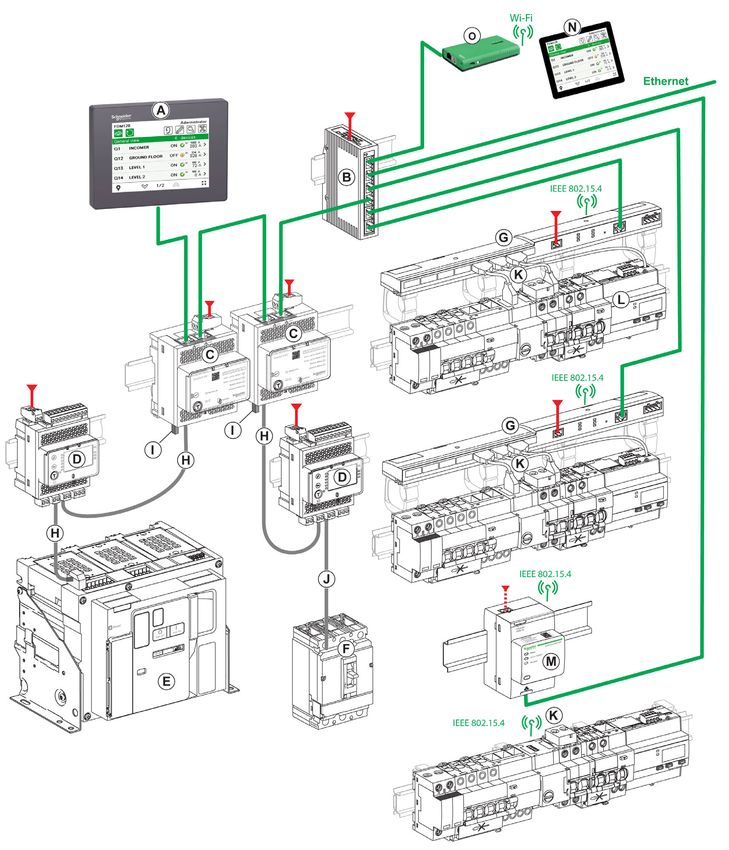
FDM128 Display Connected to Several IFE or Acti9 Smartlink SI B or Acti9 Smartlink SI D
The following diagram is an example of an IFE- and Acti9 Smartlink SI B or Acti9 Smartlink SI D-based
network architecture:
A FDM128 Ethernet display for eight devices I ULP line termination
B ConneXium switch J NSX cord
C IFE Ethernet interface for one circuit breaker K Acti9 PowerTag energy sensor
D I/O input/output application module for one circuit breaker L Acti9 Smartlink SI D
E Masterpact MTZ fixed circuit breaker Ethernet
F Compact NSX, PowerPact H-, J-, or L-frame circuit 24 Vdc
breaker TI24 cord
G Acti9 Smartlink SI B 110/230 Vac
H ULP cord
DOCA0037EN-07 01/2019 19Introduction
FDM128 Display Connected to Several Gateways
The following diagram is an example of architecture where the FDM128 display is connected to several
gateways:
A FDM128 Ethernet display for eight devices J Acti9 Smartlink Modbus
B IFE Ethernet switchboard server K EIFE embedded Ethernet interface for one
C IFM Modbus-SL interface for one circuit breaker Masterpact MTZ drawout circuit breaker
D I/O input/output application module for one circuit L ULP cord
breaker M NSX cord
E Masterpact MTZ drawout circuit breaker N Acti9 PowerTag energy sensor
F Compact NSX, PowerPact H-, J-, or L-frame circuit Ethernet
breaker Modbus-SL
G ConneXium switch 24 Vdc
H ULP line termination TI24 cord
I Acti9 Smartlink SI B
20 DOCA0037EN-07 01/2019Introduction
Component Part Numbers
The following table lists the part numbers for the components in the architecture diagrams:
Component Description Part Number
FDM128 Ethernet display for eight devices – LV434128
STU 5in7 front module spare part – HMIS85
IFE Ethernet interface for one circuit breaker – LV434001
IFE Ethernet switchboard server – LV434002
EIFE embedded Ethernet interface for one EIFE embedded Ethernet interface LV851001
Masterpact MTZ drawout circuit breaker
Spare part kit EIFE for one Masterpact MTZ1 LV851100SP
drawout circuit breaker
Spare part kit EIFE for one Masterpact LV851200SP
MTZ2/MTZ3 drawout circuit breaker
IFM Modbus-SL interface for one circuit breaker – LV434000
FDM121 ULP display for one circuit breaker – TRV00121 (IEC)
STRV00121 (UL)
I/O input/output application module for one circuit breaker – LV434063
ULP line termination 10 ULP line terminations TRV00880
ULP cord L = 0.3 m (0.98 ft) TRV00803
L = 0.6 m (1.97 ft) TRV00806
L = 1 m (3.28 ft) TRV00810
L = 2 m (6.56 ft) TRV00820
L = 3 m (9.84 ft) TRV00830
L = 5 m (16.40 ft) TRV00850
BCM ULP cord L = 0.35 m (1.15 ft) LV434195
L = 1.3 m (4.26 ft) LV434196
L = 3 m (9.84 ft) LV434197
TI24 cord - A9XCAS06
NSX cord L = 0.35 m (1.15 ft) LV434200
L = 1.3 m (4.27 ft) LV434201
L = 3 m (9.84 ft) LV434202
Acti9 Smartlink SI B – A9XMZA08
Acti9 Smartlink Modbus – A9XMSB11
Acti9 Smartlink SI D – A9XMWA20
PowerLogic EGX300 Ethernet gateway – EGX300 (Schneider Electric)
EGX300SD (Square D)
iEM2000T energy meter Single-phase energy meter without display A9MEM2000T
iEM3110 energy meter Three-phase energy meter with display A9MEM3110
iEM3155 energy meter Three-phase energy meter with display A9MEM3155
iEM3210 energy meter Three-phase energy meter with display A9MEM3210
iEM3255 energy meter Three-phase energy meter with display A9MEM3255
DOCA0037EN-07 01/2019 21Introduction
Component Description Part Number
Acti9 PowerTag energy sensor One-phase wireless energy sensor A9MEM1520
One-phase and neutral wireless energy A9MEM1521
sensor
One-phase and neutral wireless energy A9MEM1522
sensor
Three-phase wireless energy sensor A9MEM1540
Three-phase and neutral wireless energy A9MEM1541
sensor
Three-phase and neutral wireless energy A9MEM1542
sensor
One-phase and neutral wireless energy A9MEM1560
sensor
One-phase and neutral wireless energy A9MEM1561
sensor
One-phase and neutral wireless energy A9MEM1562
sensor
One-phase and neutral wireless energy A9MEM1563
sensor
Three-phase and neutral wireless energy A9MEM1570
sensor
Three-phase and neutral wireless energy A9MEM1571
sensor
Three-phase and neutral wireless energy A9MEM1572
sensor
PowerTag NSX Wireless Communication Energy Sensor Three-phase wireless communication energy LV434020
3P for Compact NSX100–250, Compact INS250, Compact sensor
INV100–250
PowerTag NSX Wireless Communication Energy Sensor Four-pole wireless communication energy LV434021
4P for Compact NSX100–250, Compact INS250, Compact sensor
INV100–250
PowerTag NSX Wireless Communication Energy Sensor Three-phase wireless communication energy LV434022
3P for Compact NSX400–630, Compact INS320–630, sensor
Compact INV320–630
PowerTag NSX Wireless Communication Energy Sensor Four-pole wireless communication energy LV434023
4P for Compact NSX400–630, Compact INS320–630, sensor
Compact INV320–630
NOTE: The Acti9 Smartlink product range is not available in the following countries: United States,
Canada, Mexico. Consult the catalog for the list of products available in your country.
22 DOCA0037EN-07 01/2019Introduction
Recommendations
Critical Systems, Alarms, and Handling Requirements
Critical alarm indicators and system functions require independent and redundant hardware protection
and/or mechanical interlocks.
If the FDM128 Ethernet display for eight devices becomes inoperative due to some reason (for example,
due to an inoperative backlight), it may be difficult or impossible to identify a function. Functions that may
present a hazard if not immediately executed, such as an emergency stop, must be provided
independently of the FDM128 display.
The design of the control system must take into account simultaneously:
An inoperative FDM128 display.
The operator inability to control the circuit breakers or to respond to detected errors by using the
FDM128 display.
Handling the LCD Panel
The following characteristics are specific to the LCD panel and are considered normal behavior:
LCD screen may show unevenness in the brightness of certain images. These images may appear
differently when seen from outside the specified viewing angle. Extended shadows, or cross-talk, may
also appear on the sides of screen images.
LCD screen pixels may contain black and white-colored spots and color display may seem to have
changed over time.
When the same image is displayed for a long period, an after-image may appear when the image
changes. If this happens, turn off the FDM128 display, wait 10 seconds, and then restart it.
NOTE: Do not display the same image for a long time, change the screen image periodically.
CAUTION
SERIOUS EYE AND SKIN INJURY
The liquid present in the LCD panel contains an irritant:
Avoid direct skin contact with the liquid.
Wear gloves when you handle a broken or leaking FDM128 display.
Do not use sharp objects or tools in the vicinity of the LCD touch panel.
Handle the LCD panel carefully to prevent puncture, bursting, or cracking of the panel material.
If the panel is damaged and any liquid comes in contact with your skin, immediately rinse the area with
running water for at least 15 minutes.
If the liquid gets in your eyes, immediately rinse your eyes with running water for at least 15 minutes and
consult a doctor.
Failure to follow these instructions can result in injury or equipment damage.
Using the Touch Panel Correctly
WARNING
UNINTENDED EQUIPMENT OPERATION
Operate the touch panel with only one finger.
Do not activate two or more points of the touch panel simultaneously.
Failure to follow these instructions can result in death, serious injury, or equipment damage.
Use only one finger to select an object on the touch panel.
If the touch panel receives pressure at two or more points at the same time, an unintended object could be
selected.
DOCA0037EN-07 01/2019 23Introduction
Certifications and Standards
Introduction
Schneider Electric has submitted this product for independent testing and qualification by third-party listing
agencies. These agencies have certified this product as meeting the following standards.
The FDM128 display is certified by the Underwriters Laboratories according to UL 508 for Industrial Control
Equipment.
The FDM128 display is designed to comply with merchant navy bridge and deck requirements (refer to the
Schneider Electric website for installation guidelines).
For detailed information, contact your local distributor or see the catalog and marking on the product.
Compliance with Standards
The FDM128 display complies with the following standards:
IEC 60947-1 general rules
UL 508, Industrial Control Equipment
CSA C22.2 No. 14-05 Industrial Control Equipment
IACS E10
Hazardous Substances
The FDM128 display is designed for compliance with the following directives and standards:
WEEE, Directive 2002/96/EC
RoHS, Directive 2002/95/EC
RoHS China, Standard SJ/T 11363-2006
UL Conditions of Acceptability for the FDM128 Display
The FDM128 display is suitable for use in hazardous locations in accordance with Class 1, Division 2
standards. All relevant local, state, and regional codes must be followed.
CE Markings
This product conforms to the requirements for applying the label.
WARNING
RISK OF EXPLOSION IN HAZARDOUS LOCATIONS
Verify that the power, input, and output (I/O) wiring are in accordance with Class I, Division 2 wiring
methods.
Do not substitute components that could impair compliance to Class I, Division 2.
Do not connect or disconnect equipment unless power has been switched off or the area is known to
be non-hazardous.
Securely lock externally connected units and each interface before turning on the power supply.
Do not disconnect while the circuit is live.
Front panel is a potential electrostatic charging hazard. Wipe the front panel of the terminal with a
damp cloth before turning on.
Failure to follow these instructions can result in death, serious injury, or equipment damage.
24 DOCA0037EN-07 01/2019Introduction
General Specifications
Electrical Characteristics
Characteristic Value
Rated input voltage 24 Vdc
Input voltage limits 20.4–28.8 Vdc
Acceptable voltage drop ≤ 7 ms
Power consumption ≤ 6.8 W
In-rush current ≤ 30 A
Voltage endurance between power terminal and functional ground 1,000 Vac 20 mA for 1 minute
(FG)
Insulation resistance between power terminal and functional 10 MΩ or higher at 500 Vdc
ground (FG)
Physical Characteristics
Characteristic Value
Ambient operating temperature (cabinet interior and panel face) –10 °C to +55 °C (14–131 °F)
Storage temperature –40 °C to +85 °C (–40 °F to +185 °F)
Relative humidity 95 % without condensation (non-condensing, wet bulb temperature
55 °C (131 °F) or less)
Air purity (dust) ≤ 0.1 mg/m3 (≤ 10-7 oz/ft3) (non-conductive levels)
Corrosive gases Free of corrosive gases
Atmospheric pressure 800–1,114 hPa (2000 m (6,500 ft) or lower)
Mechanical Characteristics
Characteristic Value
Vibration immunity (operating) IEC 60068-2-6
1 gn (1 g) 5–150 Hz (maximum 3.5 mm (0.13 in.))
Protection (front panel) IP65 (IEC 60529)
Protection structure Type 4X indoor, installed on a panel
Protection (rear panel) IP20 (IEC 60529)
Shock immunity (operating) IK05 (IEC 60068-2-75)
15 gn (1 g) 11 ms
Cooling method Natural air circulation
Weight 0.25 kg (0.55 lb.)
Color Front bezel: dark gray
Material PC/PBT and PAA
Electrical Environment Specifications
Characteristic Value
Noise immunity Noise voltage: 1,000 Vp-p
Pulse width: 1 µs
Rising time: 1 ns
High energy surges 2 kV CM, 0.5 kV DM on DC power supply
2 kV CM on shielded cables
Electrical fast transient burst 2 kV CM, 2 kV DM on DC power supply
1 kV on shielded cables
Radiated radio frequency electromagnetic field 10 V/m / 80 MHz to 2 GHz
Sinus amplitude modulated 80 %
1 kHz + internal clock frequency
CM: Common Mode
DM: Differential Mode
DOCA0037EN-07 01/2019 25Introduction
Characteristic Value
Electrostatic discharge immunity 8.8 kV direct contact
12 kV air contact
Power frequency magnetic field 100 A/m continuous
Grounding D-type grounding (SG-FG connected)
CM: Common Mode
DM: Differential Mode
26 DOCA0037EN-07 01/2019Introduction
Functional Specifications
Display Characteristics
Characteristic Description
Type Color TFT LCD
Resolution (pixels) 320 x 240 (QVGA)
Active display area (W x H) 115.2 x 86.4 mm (4.53 x 3.40 in.)
Display colors 65,536 colors
Backlight LED backlight
Lifetime: 50,000 hours before dimmed to 50 % brightness
Ambient temperature: 25 °C (77 °F)
Non-exchangeable
Brightness adjustment 16 levels of adjustment available via touch panel in the General settings menu.
Brightness on LCD surface White LED: 350 cd/m2 (33 cd/ft2) maximum
View angle 80 degrees: left, right
70 degrees: up
70 degrees: down
(Test condition: contrast ratio > 2)
Clock
Variations in operating conditions can cause a clock shift from -380 seconds to +90 seconds per month.
Touch Panel
Characteristic Description
Type Analog resistance film type (metal tab, golden plated)
Lifetime 1 million touches or more
DOCA0037EN-07 01/2019 27Introduction
Interface Specifications
USB1 Interface (USB Peripherals)
HOST Interface Characteristic Value
Transmission speed High speed 480 Mbps
Full speed 12 Mbps
Low speed 1.5 Mbps
Maximum current supplied 250 mA
Maximum transmission distance 5 m (16.40 ft) at 12 Mbps
Connector USB Type-A V2.0
Ethernet Interface
LED Description
Green 1 Link state
Green 2 Activity
28 DOCA0037EN-07 01/2019Enerlin'X FDM128
Presentation
DOCA0037EN-07 01/2019
Chapter 2
Presentation
Presentation
What Is in This Chapter?
This chapter contains the following topics:
Topic Page
Screen 30
Menu Structure 32
Browsing 33
DOCA0037EN-07 01/2019 29Presentation
Screen
Overview
The following figure describes the display area:
A Header
B Title bar
C Headpiece
D Right area
E Left area
F Footer
Header
The header (A) is composed of the following elements:
Product name (FDM128) and access profile
Direct-access icons to the main functions
Icon Description
Go to General view menu (see page 46).
Refresh the display of the names of connected devices.
Locate the device (or intelligent modular unit) (see page 47).
Go to Login/Password settings menu (see page 44).
Go to Editing devices menu (see page 40).
Go to Communication settings menu (see page 37).
Go to General settings menu (see page 37).
Title Bar
The title bar (B) contains the title of the screen or name of the selected device.
30 DOCA0037EN-07 01/2019Presentation
Main Area
The main area includes the headpiece (C), the right area (D), and the left area (E).
The following table describes the parts of the main display area:
Position Description Use
Headpiece (C) Right area title Navigate through the submenus items.
Right area (D) Information Displays information of the selected submenu or submenu item.
Information screens depend on the device.
Left area (E) Submenus, if applicable Navigate through the submenus.
Various contents depending on the device.
Footer
The footer (F) contains some navigation icons depending on the selected screen.
The icons are listed in the appendix (see page 69).
If there is more than one page in the selected submenu, the screen number is displayed. The screen
number format is X/Y, where X is the current screen number and Y is the total number of screens.
DOCA0037EN-07 01/2019 31Presentation
Menu Structure
Menu Types
FDM128 menus are divided into two types:
Settings menus: blue title bar background
Operation menus: green title bar background
Settings Menus
Settings menus are composed of two sequences:
General settings sequence
Settings sequence for devices: communication settings, device discovery, and editing devices
The setting wizard (see page 37) of the FDM128 display guides you through these sequences.
General View
The General view menu is used to monitor up to eight devices at the same time.
For further information, refer to the general view topic (see page 46).
Device View
Device view menus are only accessible from the General view menu.
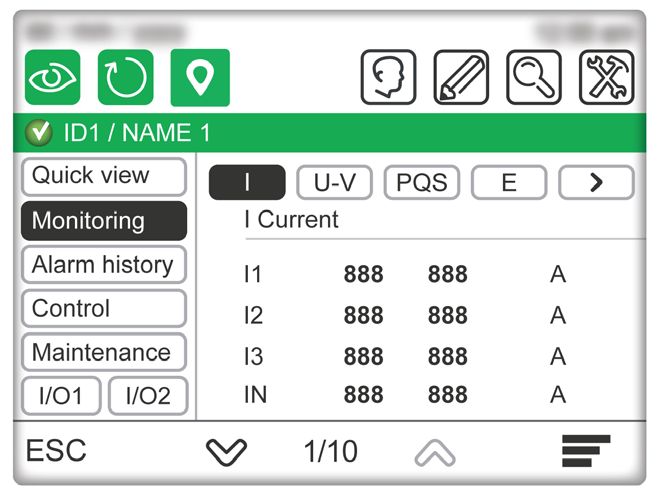
The Device view for circuit breakers menu is composed of the following submenus:
Quick view (see page 52)
Measures (see page 52)
Alarm history (see page 52)
Control (see page 53)
Maintenance (see page 54)
I/O1 and I/O2 (see page 54)
The Device view for Acti9 Smartlink SI B menu is composed of the following submenus:
Status
Counters (energy, water, gas...)
Control (see page 56)
PowerTag (see page 56)
The Device view for Acti9 Smartlink SI D menu is composed of PowerTag submenu (see page 56).
32 DOCA0037EN-07 01/2019Presentation
Browsing
Navigate Through the Screens
In a menu or a submenu, you can navigate through the screens by using the footer icons.
The browsing actions are executable by pressing the icons. Refer to the icon list (see page 69) to get the
meaning of each of them.
The icons are available depending on the network configuration, the selected menu, and the possible
actions.
NOTE: A gray icon means that the option or action is not available in the actual context.
Data Entry
When an action requires an alphanumeric entry (for example, typing a designation), the following touch
keyboard is displayed:
When an action requires a numeric entry (for example, typing an IP address), the numeric keyboard is
displayed.
NOTE: You can also display the numeric keyboard by pressing the 123 key on the alphanumeric keyboard.
DOCA0037EN-07 01/2019 33Presentation 34 DOCA0037EN-07 01/2019
Enerlin'X FDM128
                           Configuration
                           DOCA0037EN-07 01/2019

                        Chapter 3
                        Configuration

                        Configuration

What Is in This Chapter?
                        This chapter contains the following topics:
                                                                      Topic   Page
                           Prerequisites                                      36
                           Setting Wizard                                     37
                           Settings During Operation                          40

DOCA0037EN-07 01/2019                                                                35
Configuration
Prerequisites
Ethernet Network
The Ethernet connections of the IP devices in the Ethernet network must be correctly installed and
configured.
NOTE: To connect to an Ethernet device outside the subnetwork a popup message requests your
confirmation to connect to another subnetwork.
The Ethernet network may include the following IP devices:
EGX300 or EGX100 gateways
Link150 gateways
IFE or EIFE interfaces
IFE server
Acti9 Smartlink Ethernet devices
Acti9 Smartlink SI B
Acti9 Smartlink SI D
PowerTag Link
PowerTag Link HD
Third-party gateways
For further information, refer to the corresponding user guides (see page 8).
Modbus Serial Line Network
The devices in the Modbus serial line network must be correctly installed and configured with the following
Modbus parameters:
Parameter Value
Modbus address (slaves only) The Modbus address of each monitored device must be unique. The range of Modbus addresses is [1-247].
Physical interface RS-485 2-wire
Transmission mode RTU (Automatic)
Communication speed The communication speed must be the same for all devices.
Parity The parity must be the same for all devices.
Response time-out 1 second
To check the Modbus parameters of each monitored device, refer to (see page 8):
The BCM ULP Circuit Breaker Communication Module Installation Manual
The IFM Modbus-SL Interface for One Breaker - Instruction Sheet
The Acti9 Smartlink Modbus Communication System User Manual
Architecture Network Limitation
The limitations of the architecture network are as follows:
Modbus serial line time out in the IFE device should be 1 s
To avoid communication error or not to overload the network, a maximum of two FDM128 displays must
be connected to the same IFE device. The FDM128 displays can scan data of the same circuit breaker.
36 DOCA0037EN-07 01/2019Configuration
Setting Wizard
Wizard Presentation
A setting wizard is automatically launched at first power-on to help you set up the FDM128 display.
The setting wizard guides you through three main configuration parts:
1. FDM128 display general settings
2. Communication settings depending on the network architecture
3. Editing device function
Each configuration part is described further in this section.
It is recommended that you update the communication settings each time you modify the communication
network.
General Settings
The following table describes the sequence of steps presented by the setting wizard to configure the
FDM128 general settings:
Step Screen Action
1 Welcome Touch the screen to start the wizard.
2 Language Select a language.
In the footer, press to access the next step.
3 Refresh Rate Press one of the two possible ways to set manually the real-time sample rate in the General View:
Fast (default setting): refresh every 3 s for circuit breakers and 5 s for Acti9 Smartlink.
Slow: refresh every 10 s for all devices.
Example:
8 Masterpact MTZ circuit breakers connected in Fast refresh mode has a maximum duration
equal to (8x3) = 24 seconds.
8 Masterpact MTZ circuit breakers connected in Slow refresh mode has a maximum duration
equal to (8x10) = 80 seconds.
In the footer, press to access the next step.
4 Phase labels Press one of the two possible ways to represent the phases 1,2,3,N (default setting), or A,B,C,N.
In the footer, press to access the next step.
5 Units of measurement I/O Select the units of measurement for the analog input of the I/O modules:
The unit of temperature (°C (default setting) or °F)
The unit of volume (m3 (default setting) or gallon US or gallon UK)
In the footer, press to access the next step.
6 Brightness Press the -/+ icons to adjust the brightness level of the display.
In the footer, press Finish.
The setting wizard displays the Selection of the communication architecture screen to allow you
to set up the FDM128 communication. Follow the communication settings procedure that
corresponds to your network architecture.
Communication Settings for a Single Gateway-Based Architecture
This procedure is applicable when:
The FDM128 display is connected to an IFE interface (see page 19) or an EIFE interface (see page 15)
The FDM128 display is connected to an Acti9 Smartlink SI B or Acti9 Smartlink SI D gateway
(see page 16)
The FDM128 display is connected to an EGX gateway
DOCA0037EN-07 01/2019 37Configuration
The FDM128 setting wizard guides you through the following steps:
Step Action
1 Configure the FDM128 display within the network.
Set the following parameters:
The FDM128 IP address
The subnet mask
The default gateway IP address
2 Press YES to indicate that the FDM128 display is connected to a gateway.
3 Set the IP address of the gateway.
4 Enter Modbus range between 1–247.
5 Press Start to launch the device discovery sequence (see page 39).
Up to 16 devices are displayed.
6 Select up to eight devices among the devices displayed.
7 If you select fewer than eight devices among the devices displayed, you are prompted for an additional gateway. Press NO.
8 If needed, you can configure manually extra IFE, EIFE, Acti9 Smartlink SI B, or Acti9 Smartlink SI D devices.
9 Press Finish.
The FDM128 display can now monitor the list of selected devices.
The setting wizard displays the Editing devices screen to allow you to edit the label and name of the devices.
Communication Settings for Several Gateway-Based Architectures
This procedure is applicable when the FDM128 display is connected to several gateways (see page 20).
The FDM128 setting wizard guides you through the following steps:
Step Action
1 Configure the FDM128 display within the network.
Set the following parameters:
The FDM128 IP address
The subnet mask
The default gateway IP address
2 Press YES to indicate that the FDM128 display is connected to a gateway.
3 Set the IP address of the gateway.
4 Enter Modbus range between 1–247.
5 Press Start to launch the device discovery sequence (see page 39).
Up to 16 devices are displayed.
6 Select up to eight devices among the devices displayed.
7 If you select fewer than eight devices among the devices displayed, you are prompted for an additional gateway.
If you have another gateway to configure, press YES and go back to step 3.
8 When you have configured all gateways, press NO. You can now manually configure extra IFE, EIFE, Acti9 Smartlink SI B, or
Acti9 Smartlink SI D devices.
9 Press Finish.
The FDM128 display can now monitor the list of selected devices.
The setting wizard displays the Editing devices screen to allow you to edit the label and name of the devices.
NOTE: Before launching the auto discovery, make sure that the Modbus serial line time out is 1 s.
Communication Settings for Several IFE, EIFE, Acti9 Smartlink SI B, or Acti9 Smartlink SI D Architecture
The procedure is applicable when the FDM128 display is connected to several IFE, EIFE , Acti9 Smartlink
SI B, or Acti9 Smartlink SI D (see page 19) devices.
The FDM128 setting wizard guides you through the following steps:
Step Action
1 Configure the FDM128 display within the network.
Set the following parameters:
The FDM128 IP address
The subnet mask
The default gateway IP address
2 Press NO to indicate that there is no gateway.
38 DOCA0037EN-07 01/2019Configuration
Step Action
3 Configure manually up to eight IFE, EIFE, Acti9 Smartlink SI B, or Acti9 Smartlink SI D devices.
4 Press Finish.
The FDM128 display can now monitor the list of selected devices.
The setting wizard displays the Editing devices screen to allow you to edit the label and name of the devices.
Device Discovery
The device discovery feature enables detection of devices in a given Modbus range (1–247).
NOTE: The default Modbus range is 1–10.
The device discovery sequence detects up to 16 devices on the network as per the given Modbus range.
These devices are displayed sorted in ascending order of Modbus address, with the Modbus address
indicated in the first column.
The device discovery sequence time varies depending on the Modbus range selected.
NOTE: The 16 detected devices are those with the 16 first Modbus addresses.
Among the detected devices, you can select a maximum of eight devices.
The FDM128 display guides you through the following device discovery procedure:
Step Action
1 The device discovery sequence is started during the communication settings procedure.
A progress bar is displayed during the device discovery sequence.
NOTE: During the device discovery, if you want to stop the discovery sequence, press Cancel. It will take you back to the Device
Discovery page.
2 In the list of the discovered devices, select the check box for each device you want to include.
Devices previously selected in a device discovery loop are displayed in gray.
3 Press Finish.
The Editing devices screen appears.
Manual Configuration of IFE, EIFE, Acti9 Smartlink SI B, and Acti9 Smartlink SI D
You configure devices manually either after a device discovery sequence, or if you do not have a IFE,
EIFE, Acti9 Smartlink SI B, or Acti9 Smartlink SI D gateway.
To configure devices manually during the device settings sequence, proceed as follows:
Step Action
1 On the configuration screen, tick the check boxes of the number of IFE, EIFE, Acti9 Smartlink SI B, or Acti9 Smartlink SI D
devices to configure.
2 For each selected device, set its IP address.
3 Press OK.
Power Loss
In case of power loss, the FDM128 display retains the settings.
DOCA0037EN-07 01/2019 39Configuration
Settings During Operation
General Settings
Setting functions that can be used during operation, without restarting the setting wizard, are:
Modifying the general settings
Editing devices
Adding single IP devices manually
During operation, you can access the General settings menu by pressing .
Editing Devices
Limitations
When the following devices are used together, you cannot write or edit the device name:
Masterpact with BCM module, firmware version lower than 3.2.5.
Compact NS with BCM module, firmware version lower than 3.2.5.
PowerPact P- and R-frame with BCM module, firmware version lower than 3.2.5.
An example network architecture is provided in this guide (see page 18).
Prerequisites
Before editing devices, you must verify that the following prerequisites are met:
Circuit breaker must be in the remote control mode.
Device logging in the IFE or EIFE webpage must be disabled.
Only the following characters are allowed:
Upper case letters from A to Z
Lower case letters from a to z
Digits from 0 to 9
Hyphen -
Before editing the name and label of the circuit breaker:
The EIFE intrusive command mode must be unlocked
The locking pad of the IFE, or IFM interface must point to the open padlock, as shown in the following
graphic
When the communication network is configured, access the Editing devices menu by pressing .
Use the Editing devices menu to:
Provide a label for each device:
The label is defined in the ID field and is only displayed in the FDM128 display. The ID field contains up
to 4 characters.
Rename a device:
The name is defined in Name field and is the actual name of the device. You may need to use the device
password to rename the device. The Name field contains up to 12 characters.
NOTE: Press OK to validate the settings and go back to the operation mode.
40 DOCA0037EN-07 01/2019Configuration
Communications Settings
During operation, you can access the Communication settings menu by pressing .
Use this menu to:
View the present communication settings configuration.
Restart the setting wizard (see page 37), beginning at the point following the general settings, where
you can modify the FDM128 display settings.
If the number of devices is less than eight, manually add an IFE interface, an EIFE interface, an Acti9
Smartlink SI B, or an Acti9 Smartlink SI D.
Password Settings
During operation, you can access the Password settings menu by pressing . Use this menu to view
and edit user login and password settings (see page 44).
DOCA0037EN-07 01/2019 41Configuration 42 DOCA0037EN-07 01/2019
Enerlin'X FDM128
                          Operation
                          DOCA0037EN-07 01/2019

                        Chapter 4
                        Operation

                        Operation

What Is in This Chapter?
                        This chapter contains the following topics:
                                                                         Topic         Page
                           Logins and Passwords                                        44
                           General View                                                46
                           Real-Time Alarms                                            49
                           Device View for Circuit Breakers and Switch-Disconnectors   51
                           Device View for Devices Connected to the Acti9 Smartlink    55

DOCA0037EN-07 01/2019                                                                         43
Operation
Logins and Passwords
Levels of Access
The FDM128 display requires login and password combinations to access the following functions:
Monitoring functions:
By default, you do not need to log in to access monitoring functions (viewer or guest) access).
Operation functions:
Log in as an operator to access operation functions (operator access).
Administration, communication, and other advanced functions:
Log in as administrator to access advanced functions (administrator access).
The various functions that available at different access levels are listed in the table.
Function Type Guest Operator Administrator
IO output control Control No Yes Yes
Light and load control Control No Yes Yes
Breaker control Control No No Yes
Acti9 device control Control No Yes Yes
Reset measurement (min max, energy) Configuration No Yes Yes
Edit breaker device names Configuration No No Yes
Discovery of devices Configuration No No Yes
General settings (language, date, brightness) Configuration No Yes Yes
Configuration of login and password Configuration No No Yes
Monitoring Monitor Yes Yes Yes
NOTE: Menus and functions that are not available at an access level are grayed out.
Login Procedure
To log in to the FDM128 display, follow these steps:
Step Action
1
Press .
The Operator/Administrator access screen opens.
2 Enter your login and password.
3 Press OK.
In the screen header, you can now access the direct function icons for your level.
Logout Procedure
To log out of the FDM128 display, follow these steps:
Step Action
1
When you are logged in to the FDM128 display, press .
The Login/Password management screen opens.
2 Press Logout.
3 When prompted to confirm logout, press YES.
In the screen header, you can now access only the Login/Password function icon.
NOTE: If you do not touch any button or function on the FDM128 display for 25 minutes, you are
automatically logged out.
44 DOCA0037EN-07 01/2019Operation
Configuring Logins and Passwords
The predefined default user login/password combinations are:
For the administrator: admin/admin
For the operator: oper/oper
If you need to change a login name or password, follow these steps:
Step Action
1 Log in as administrator.
In the General view screen, in the screen header, you can now access all the direct function icons.
2
Press .
The Login/Password management screen opens.
3 Press Configuration.
The Operator : login configuration screen opens.
4 Type the new login for an operator.
The login:
Is case-sensitive.
Can contain from 1 to 16 characters.
Can contain alphanumeric characters and symbols, excluding the space character.
After editing the operator login value, press to go to the next screen.
The Operator : password configuration screen opens.
5 Type the new password for an operator.
The password:
Is case-sensitive.
Can contain from 1 to 16 characters.
Can contain alphanumeric characters and symbols, excluding the space character.
After editing the operator password value, press to go to the next screen.
The Administrator : login configuration screen opens.
6 Type the new login for an administrator.
The login:
Is case-sensitive.
Can contain from 1 to 16 characters.
Can contain alphanumeric characters and symbols, excluding the space character.
After editing the administrator login value, press to go to the next screen.
The Administrator : password configuration screen opens.
7 Type the new password for an administrator.
The login:
Is case-sensitive.
Can contain from 1 to 16 characters.
Can contain alphanumeric characters and symbols, excluding the space character.
After editing the administrator password value, do one of the following:
Press one or more times to go back to previous login and password configuration screens.
Press OK.
8 When prompted to confirm changes to the logins and passwords, press YES.
Login/Password Reset
You can restore the default login and password settings by pressing and holding it down for
10 seconds.
DOCA0037EN-07 01/2019 45You can also read