ENSURING A SAFE FUTURE DRINKING WATER SUPPLY FOR THE RANGITAIKI PLAINS
←
→
Page content transcription
If your browser does not render page correctly, please read the page content below
ENSURING A SAFE FUTURE DRINKING
WATER SUPPLY FOR THE RANGITAIKI
PLAINS
S. Sandhu (Pattle Delamore Partners Ltd – 89 Grey Street, Tauranga)
J. Graham (Pattle Delamore Partners Ltd – 89 Grey Street, Tauranga)
L. Salanguit (Whakatane District Council – 14 Commerce Street, Whakatane)

ABSTRACT
Bores at Braemar Springs, Johnson Road and Tahuna Road historically supplied the
Edgecumbe and Te Teko townships and rural Rangitaiki Plains area. Braemar and
Johnson Road water contain levels of arsenic and antimony above the DWSNZ. The
shallow, flood affected Tahuna Road bore did not comply with DWSNZ. These sources
are not Secure Water Sources for human consumption but are suitable for rural and
agricultural use.

Whakatāne District Council (WDC) must provide a potable water service complying with
DWSNZ to Edgecumbe and Te Teko. The remainder of the Rangitaiki Plains water service
must comply with RADWS. Both of these services must meet pressure and flow
standards. The Otumahi Water Supply Scheme initially solved all these issues but
budgetary constraints and permitting limitations restricted the extent to which this could
be achieved. WDC consulted the public and local Iwi to prioritize sub-regions within the
network to reduce the scheme. Edgecumbe and Te Teko were identified as townships
where the DWSNZ apply. Eastern Rangitaiki Plains can continue being supplied to
RADWS.

The final Otumahi Water Supply Scheme developed an existing bore and constructed new
treatment and pumping facilities on council land at Paul Road. A 169m deep bore with
DWSNZ compliant water characteristics exists on site. Bore headworks, chlorine and
caustic dosing facilities, storage tanks and a pump station were constructed for the
scheme.

A second contract constructed 9.3km of watermain from Paul Road to Edgecumbe
including the Braemar bypass. These pipelines include two bridge crossings and a bypass
to deliver RADWS water to the eastern Rangitaiki Plains. A third contract upgraded the
Tahuna Rd WTP to supply Te Teko with DWSNZ compliant water. This paper outlines the
scheme from planning to handover and discusses issues encountered. WDC’s
considerable efforts to provide safe drinking water for its people are highlighted.

KEYWORDS
Water Supply Upgrade, Water Quality, Drinking Water standards for New Zealand,
Pipeline, Treatment Plant, Chlorination, Ultraviolet Disinfection, Caustic

NOMENCLATURE
WTP = Water Treatment Plant | WDC = Whakatane District Council | DWSNZ = Drinking
Water Standards for New Zealand | RADWS = Rural and Agricultural Drinking Water
Standards

PRESENTER PROFILE
Mr. Shahbaz Sandhu – Civil and Environmental Engineer at Pattle Delamore Partners Ltd.
Shahbaz has been involved in the investigation and detailed design of the Paul Road and
Tahuna Road water supply projects.

Mrs. Leilani Salanguit – Project Engineer at Whakatane District Council. Leilani is the
Project Manager of the Paul Road and Tahuna Road water supply projects.

                   Figure 1: Rangitaiki Plains Water Supply Network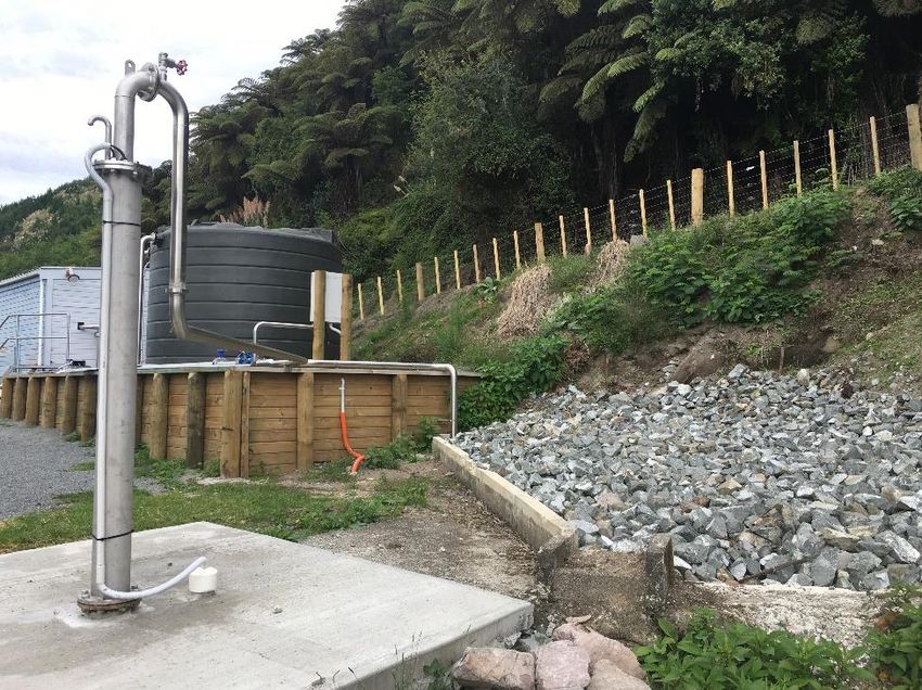
1 INTRODUCTION
Edgecumbe and Te Teko townships are supplied from the Rangitaiki Plains water supply.
This has three water sources, the Braemar Spring, Tahuna Road Bore and the Johnson
Road Bore. The Braemar source is of moderate quality with elevated levels of arsenic
(.023 mg/L). These exceed the DWSNZ Maximum Acceptable Value (MAV) of 0.01 mg/L.
The Tahuna and Johnson Road bores are not classed as secure having only partial
barriers to contamination. All supplies are chlorinated. The Johnson Road source has
recorded arsenic levels of 0.018 mg/L and 0.11 mg/L. The lack of barriers preventing
protozoa contamination and the elevated arsenic levels are the main health risks causing
a lack of compliance with DWSNZ.
Two Arsenic removal technologies have been investigated by WDC in the past,
coagulation/sedimentation/filtration/UV and G2 Absorbent Media /UV. Both options are
effective treatments however arsenic contaminated sludge is a by-product that must be
disposed of separately. Specific arsenic removal was not considered appropriate as 60-
80% of the flow would require treatment. The capital cost of this option was considered
too high for the community to bear as it required a new site and green field water
treatment plant (Opus Preliminary Design Report for Edgecumbe Drinking water supply).
Where the Rangitāiki Water Supply is used for stock water, treatment to RADWS is all
that is required.
A new source at Paul Road was drilled, pump tested and found to be secure. Resource
consent has been secured with an instantaneous flow limit of 61 l/s and a daily limit of
5280 m3/day.
Water from Paul Road could only be supplied to Edgecumbe and Te Teko because of
budgetary constraints and resource consent limits on the water take. This solution
complied with the guidelines set by the DWSNZ for Rural Agricultural Drinking Water
Supply.
A 50 year water strategy developed by Opus International Consultants Ltd for WDC in
2011 provided a number of options to upgrade the Rangitaiki Plains Water Supply. The
option selected by WDC optimized the use of funding and accommodated the resource
consent limitations while still complying with DWSNZ. The scheme delivers an “on
demand” water supply without a storage reservoir. The proposed scheme was
subsequently named the Otumahi Water Supply.
WDC engaged Pattle Delamore Partners Ltd (PDP) to develop the concept into a detailed
design for a bore field, treatment plant, pump station and bulk supply main. The Te Teko
township is supplied with potable drinking water from Tahuna Road. A combination of the
Otumahi Water Supply Scheme and an upgrade of Tahuna Road provide a joint water
supply to service Edgecumbe, Te Teko and adjoining areas.
2 PLANNING AND CONSENTS
Pattle Delamore Partners Limited (PDP) assisted WDC in the consents analysis for
Otumahi Water Supply scheme. The consents required were as follows:
Building consent for the Water Treatment Plant (WTP) building;
Earthworks consent for the pipeline as the total volume of excavated material
exceeded 5,000 m 3 ;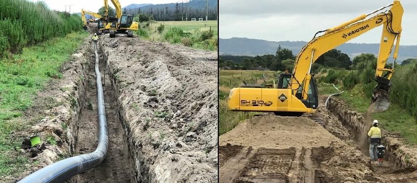
Land use consent for the storage and use of dangerous chemicals (Caustic
and Chlorine) at the Paul Road site and the construction of the pump station
building and 250 m3 steel tank;
Property consent involved an easement agreement between Kiwirail and WDC
to construct and operate in their land.
PDP completed an assessment of environmental effects and a HSNO assessment for the
land use consent application.
3 DESIGN
3.1 DELIVERY PIPELINE FROM PAUL ROAD
PDP began detailed design of the Otumahi Water Supply project in June 2016. The
pipeline conveys potable water for 8.01 km from a new pump station at 124 Paul Road to
the connection at Edgecumbe. It consists of 1.53 km of 355 OD PE100 SDR13.6 pipe,
4.11 km of 280 OD PE100 SDR13.6 pipe and 2.37 km of 250 OD PE100 SDR13.6 pipe.
5.64 km of the water main was constructed in the road reserve and 2.37 km was
constructed on Kiwi Rail land adjacent to the railway line. The key elements undertaken
by PDP in the design are listed below.
Photograph 1: Otumahi Delivery Pipeline installation
3.1.1 ROUTE SELECTION
The pipeline was installed in the berm out of the carriageway to minimise construction
costs. The route was chosen to avoid clashes with other services. The alignments
chosen have clear space within the road reserve that allows construction with a minimum
impact on traffic and the road structure.
3.1.2 ISOLATION FROM BRAEMAR SPRING
Isolating the Braemar Spring removes the source of water with excessive concentrations
of arsenic and antimony from the supply network. The loss of this water source also
lowers the pressure and flow to the eastern area of the Rangitaiki Plains. A bypass was
installed to allow Braemar Spring to continue supplying Eastern Rangitaiki at the required
pressure and flow. This part of the water supply network is separated from the
Edgecumbe network where the DWSNZ are met. This bypass is made up of 1.12 km of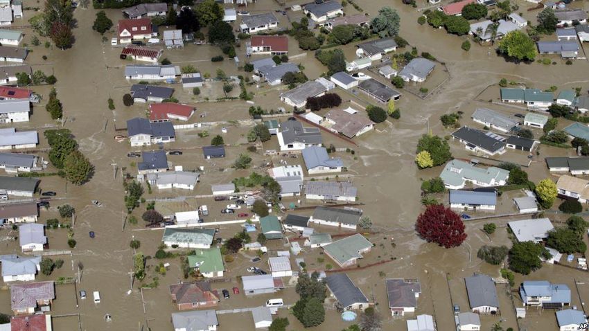
180OD-PE100 SDR-13.6 pipe along Bridge St, Tawa St and State Highway 2 plus 178
metres of 150NB 316SS pipe over the Rangitaiki Bridge. The bypass main utilizes
existing pipework as much as possible to reduce construction costs.

3.1.3   PIPE BRIDGE CROSSINGS
Pipe bridge crossings have been installed at the Reids Canal and Rangitaiki River Bridges
on SH2. The new pipeline from Paul Road crosses the Reids Canal before connecting into
the existing Edgecumbe water supply system near Hydro Road. The Braemar Spring
bypass crosses the Rangitaiki River to link with the Eastern Rangitaiki Plains part of the
network. Both crossings are 150NB 316SS pipework.

3.1.4   DESIGN FLOW REVIEW AND PIPE SIZING
Opus developed a model of the potable water network which was used to determine pipe
sizes for the original water supply option. PDP reviewed the model and made changes to
allow for budgetary and permitting constraints then re-evaluated pipe sizes for the
Otumahi Water Supply scheme ultimately approved.

PDP’s pipe network model was also used to determine pressure values in the network
and to specify the pipe. PDP prepared a transient model to locate air valves along the
pipeline.

3.2     WATER TREATMENT PLANT AT PAUL ROAD
The Paul road facility can be extended to include three additional bores. Population
growth forecasts and previous network modelling by Opus indicate the future peak hour
demand from the entire Rangitaiki Plains will be approximately 120 l/s. The three
planned bores at the Paul Road site will satisfy the future demand.

Detailed design of the Paul Road facility began in June 2016.         PDP undertook the
following key elements of design.

3.2.1   SITE LAYOUT
The layout of the booster pump and treatment facility must ensure there is a safe
distance between neighboring properties and the hazardous chemicals stored at the site.
Containers of compressed Chlorine gas and a 30% solution of sodium hydroxide are kept
at the facility to treat the raw water before it is pumped into the reticulation network.
AS/NZS 2927 stipulates that a chemical storage facility must be a minimum distance of
50 metres from the nearest residence.

The access road layout was designed using the turning circles of servicing and supply
vehicles to ensure clear unconfined access to the facility.

The Paul Road site is in a very quiet rural environment where noise can travel significant
distances. The Building containing the booster pumps and electrical equipment is
constructed with filled concrete blockwork and an insulated roof to prevent noise
escaping into the surrounding environment. The bore pump is 95 metres below ground
so will not generate significant noise at the surface.
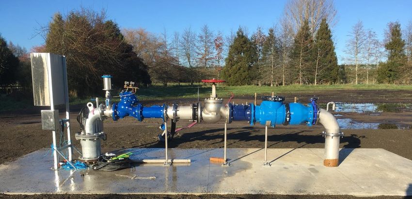
Photograph 2: Otumahi Bore Site Treatment Plant

3.2.2   BORE PUMP AND HEADWORKS

                          Photograph 3: Bore Head pipework.

An initial assessment of drawdown in the pumped bore and a neighbouring bore planned
for future development has been undertaken by others. Mean values of the hydraulic
parameters determined in the assessment have been used to estimate the draw down in
the existing Paul Road bore and the future adjacent second bore. The cumulative
drawdown in both pumping bores is predicted to be around 81m after pumping 10,368
m3/day (120 l/s), from both bores for 365 days.

The existing 250mm diameter bore at the Paul Road was drilled in 2010 to investigate
the aquifer. The investigation concluded that the water from this bore meets or exceeds
the requirements of the DWSNZ (Opus International Consultants Ltd, 2010). Age testing
of the bore indicated that the water was between 50 and 150 years old and that less than
0.005% of the water present in the aquifer was less than one year old. This satisfies the
residence time criterion (Section 4.5.21) in the DWSNZ (GNS Science Ltd, 2010).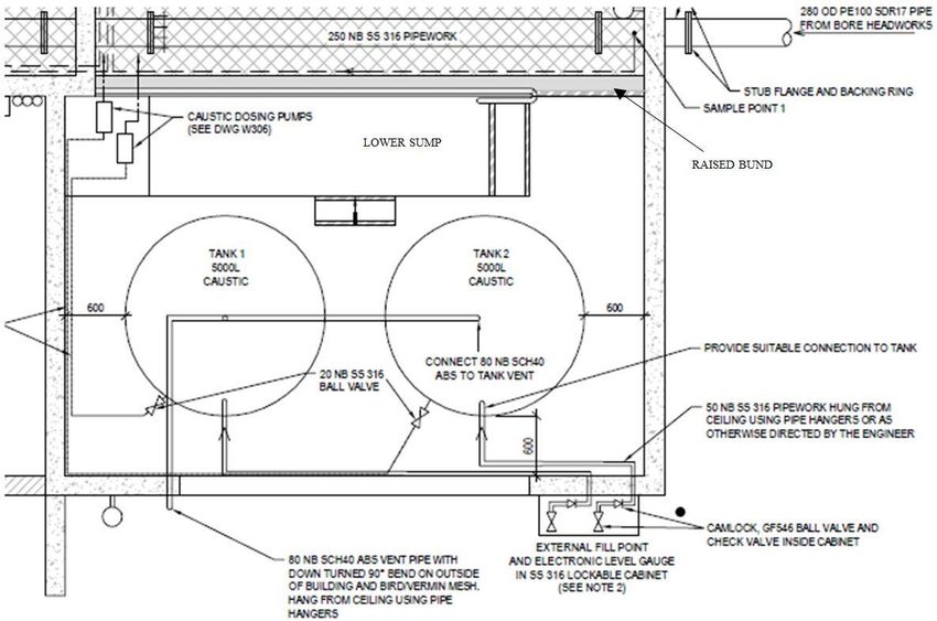
Other measures were undertaken during the design to ensure the bore is compliant with
DWSNZ. The existing bore has a sloping concrete apron surrounded by a fence offset 5m
from the edge to keep stock away from bore headworks. A tap is provided at the bore to
enable sampling of the raw water to ensure compliance with DWSNZ.

The bore pump transfers raw water through the treatment plant and into a 250 m3
contact tank. A 75kW SP 160-7-aa Grundfos pump was selected for the new bore. This
pump can deliver 50 l/s from the bore when the water level has been drawn down to
maximum 81 metre depth predicted by modelling. This pump also requires 60 metres of
pressure head to operate on its pump curve. The bore pump is positioned 95 metres
below the ground surface. The 14 metre difference in depth between the maximum
drawdown level and the bore pump protects the pump from running dry when additional
bores are installed at the site.

                        Figure 2: Paul Road Bore Pump Curve

3.2.3   BOOSTER PUMP STATION
The Paul Road WTP site is at an elevation of approximately RL 114 m (Moturiki Datum
+100m). A 77 m pump head was adopted at the Paul Road WTP to match the system
pressure identified by Opus at Te Teko and Braemar Reservoirs. The various water
source levels are shown on the schematic of the Plains Water Supply below (PDP,
2017b).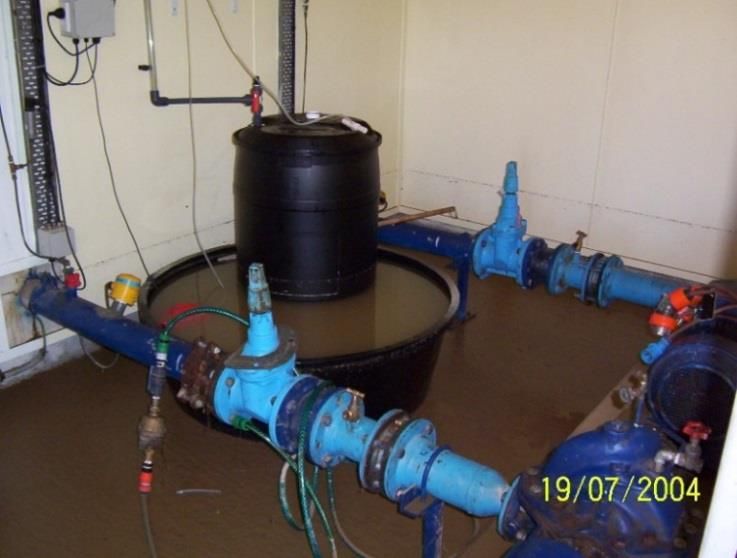
Figure 3: Rangitaiki Plains Water Supply Schematic
The booster pumps draw treated water from the contact tank and will operate on VSD
control to maintain a steady outlet pressure of 77m on the discharge side of the WTP
during periods of normal demand. The outlet pressure can be reduced during off peak
period to reduce power consumption. The booster pump skid consists of the following
three pumps.
• The CRE20-6 Jockey Pump will operate between 0 and 8.5 l/s.
• The first CR90-3-2 Pump will take over when the flow exceeds 6 l/s (with the
CRE20-6 shutting down) and run through to 30 l/s.
• The second CR90-3-2 Pump will remain as a standby in case of pump failure.
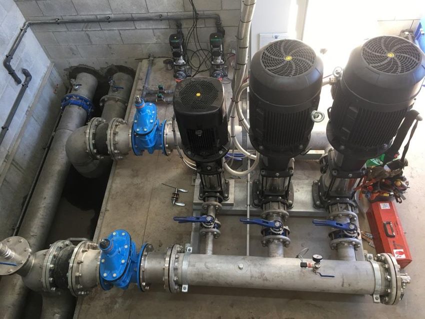
Photograph 4: Booster Pump and Manifold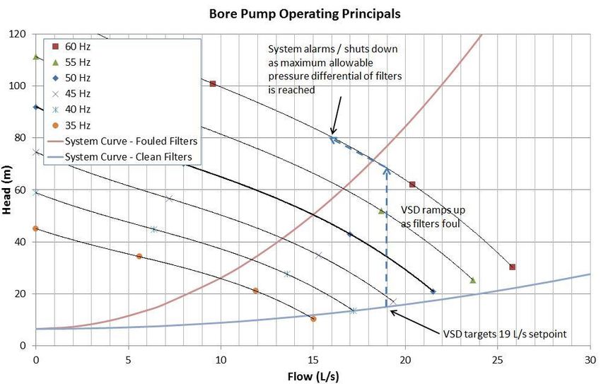
The pumps will always sit very close to their maximum efficiency point throughout the
range of expected duty points to minimizing energy consumption. The main booster
pump curves and fixed outlet pressure are shown below.

                        Figure 4: Paul Road Booster Pump Curve

3.2.4   TANKS
A 250 m3 contact tank and a 31 m3 maintenance tank were selected to provide chlorine
residence time before water is pumped into the network. The contact tank provides
approximately 3 hours of storage at the present peak demand flow of 24 l/s. This is well
above the 30 minutes residence time required by the DWSNZ. Both tanks have been
designed assuming the importance level of 3 (IL3) required by the building code for
potable water treatment facilities.

The 31m3 maintenance tank maintains service while the contact tank is isolated for
maintenance. This tank provides approximately 20 minutes retention at 24 l/s. Although,
this is less than the 30 minutes required by the DWSNZ, the remaining 10 minutes is
provided by the delivery pipework within the treatment plant site.

Both tanks have an emergency overflow in case of instrumentation failure. These
overflows are directed onto the adjacent ground. The risk of instrument failure is further
mitigated by a backup system.

Both tanks are emptied for maintenance through drainage pipes directed to the on-site
stormwater soakage pit. The contact tank will take up to 8 hours (overnight) to drain
and the maintenance tank will be drained after each use.

3.2.5   TREATMENT
The new facility includes chlorine and 30% sodium hydroxide (caustic) dosing. Caustic
dosing is controlled by the pH meter and a pH of approximately 7.5 is maintained by the
system. 5000 litres of caustic solution is held in two HSNO approved tanks bolted to the
floor inside the building. The tanks will be filled from a tanker through a camlock fitting
on the outside of the building minimizing entry into a hazardous space. The ground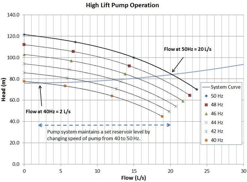
surrounding the delivery area outside the building is sealed with a concrete apron. The
apron has sufficient storage capacity to contain the accidental spill volume equal to the
largest compartment in the delivery truck (about 7,000 litres). Spills inside the building
will be contained in a concrete bund. A plan of the caustic dosing facility is shown below.

                             Figure 5: Caustic Room Layout

The chlorine gas is stored inside the building in a 920 kg chlorine gas drum and a 70 kg
backup chlorine gas cylinder. A gas leak detector linked to an alarm system has been
installed in the building and emergency valves isolate chlorine cylinders if a leak occurs.
The 920 kg chlorine gas drum is supported on rails which extend out onto the concrete
pad outside the building. The drum can be easily loaded and unloaded directly from a
truck when required. Based on the expected chlorine gas usage, it is estimated the
chlorine drum will provide sufficient gas for approximately 2 years.

Two chlorine booster pumps, installed in duty/standby configuration, deliver chlorine
carry-water to the contact tank supply pipework. This system ensures chlorine dosing
can be undertaken even when the delivery pump station is not operational.

3.3    WATER TREATMENT PLANT AT TAHUNA ROAD
PDP was engaged by WDC in September 2016 to undertake the investigation and
detailed design for the upgrade of the Tahuna Road Water Supply. The existing Tahuna
Road WTP did not meet the DWSNZ because of inadequate protection against
contamination at the bore headworks and because the treatment processes did not
provide the required treatment to achieve protozoal compliance. New cartridge filters and
a UV system has been installed to provide treatment to a level higher than that required
by DWSNZ.
Photograph 5: Tahuna Road WTP after Upgrade 3.3.1 BORE PUMP COMPLIANCE AND SELECTION Raw water is drawn from an unconfined aquifer. The bore is approximately 16 m deep (with the top of screen estimated to be 13.3 m BGL) and located in a flood zone. This characteristic prevents the bore from achieving a secure status under the DWSNZ criteria. Previously the bore head was not sealed at the surface and was prone to ingress of surface water and contaminants. The bore casing was raised 500 mm above the 100 year flood level and sealed to prevent ingress of surface water and contaminants. A new sloping concrete pad was installed around the casing and a new fence was constructed around the perimeter of the site to further improve the protection from the ingress of contaminants to comply with DWSNZ. A new bore pump was required due to the increased pump capacity required to pump through the cartridge filters. Grundfos and Lowara pumps were considered for this application and a Lowara was selected as it provides additional clearance within the bore casing. The pump will operate on a variable speed drive and the motor has been sized to allow operation up to 60 Hz. This provides the optimum arrangements of minimum energy consumption when the cartridge filters are clean whilst still maintaining high flow capacity when filters are fouled. Operation of the bore pump has been summarised below. The VSD will target a set operating flow of 19 L/s and as the filters foul the VSD will ramp the pump speed up to maintain 19 L/s. Once the pump motor speed reaches 60 Hz, the pumped flow will continue to reduce as the filters continue to foul. When the pressure differential across the filter reaches a preset level the system will alarm and shutdown. The cartridges will be replaced at that time.
Figure 6: Tahuna Rd Bore Pump Operation

3.3.2   HIGH LIFT PUMPS
The existing horizontally mounted high-lift pumps were operating at the peak of their
electrical and hydraulic capacity at 50 Hz limiting the flow from the site. They pump from
the treatment plant up to the reservoir. These were replaced with vertically mounted
pumps which provide additional operational head to allow for pumping through the new
UV system and also raise the pump motors above the 100 year flood level. The existing
pumps could not be mounted vertically.

The new pumps are operated in a duty / standby sequence and are programmed to
maintain a set water level in the Te Teko Reservoir. VSDs control the delivery flow rate.
This will limit pump starts and stops to optimise UV sterilisation. The system pump
curves are shown below along with the operating principals.
Figure 7: Tahuna Road High Lift Pumps Operation

3.3.3   WATER TANK
A new 31m3 flow balancing water tank has replaced the existing 25m3 water tank at the
site. This will reduce the number of stop / starts of the bore pump and reduce the time
and volume of the bore water discharged to waste. The tank also provides additional
buffering capacity, in case additional flow capacity is required at the site and a second
bore is installed at the site in the future.

3.3.4   TREATMENT COMPLIANCE
The old hypochlorite system has been replaced with chlorine gas at the site to provide
residual disinfection in the network and achieve the requirements of the DWSNZ. The
chlorination rate is set to achieve 1ppm of chlorine residual leaving the WTP at Tahuna
Road. The chlorine retention time is over 6 hours, well above the minimum 30 minutes
requirement of the DWSNZ. On-site storage and off-site storage at Te Teko Reservoir
provide the chlorine retention time.

The previous treatment processes did not achieve the requirements of the DWSNZ. A
shallow bore requires 3 log credits for protozoal compliance. Cartridge filtration with
ultraviolet light (UV) disinfection provides a total of 5 log credits (2 and 3 log credits
respectively).

The site experiences elevated levels of turbidity when the adjacent river rises. This
suggests a direct link between the bore and surface water. If the site was conservatively
assumed to be a surface water source, the DWSNZ would require a 5 log credit
treatment. The new treatment infrastructure provides 5 log credits.
3.3.5    SUMMARY
The equipment selected, the hydraulic capacity and the treatment capacity of each
aspect of the process at the site has been summarised in the table below.

                              Table 1: Tahuna Road Design Summary

        Design                                                                           Capacity
                                 Details                    General Notes
        Aspect                                                                            (l/s)

                        6" bore (154 mm inside
                        diameter) with top of
                        screen depth estimated at     Measured static water level of
        Existing Bore   13.3 m BGL from on-site       1.5 m BGL, estimated 2.0 m
                        measurements and total        BGL during pumping at 16 l/s
                                                                                            19
                        depth of 16 m (WDC
                        website)

                        Lowara Z660/6 with 22 kW
        Bore Pump                                     - Capable of pumping at 19 l/s
                        motor

                                                      - Capacity of up to 55 l/s.
                        2 No. 3M CUNO High Flow       - 15/10/5 micron filters provide
                        Cartridge Filters including   pre-treatment
        Cartridge       3 x 15/10/5 Micron            - 1 micron filters provides
                                                                                            55
        Filters         Cartridges and 3 x 1          drinking water compliance
                        Micron Cartridges installed   - Wasting required at the start
                        in series                     of each filtering cycle (each
                                                      time bore pump starts)

                        DN 100 electrically           - Discharges a set volume of
        Wasting Valve   actuated butterfly valve,     water to waste at the beginning       -
                        brand not specified           of each bore pump cycle

                        2 x 70 kg Chlorine gas
                        cylinders with automated
                                                      - Capacity well in excess of 50
        Chlorination    switchover, scales, 400                                            >50
                                                      l/s
                        g/hr chlorination and gas
                        leak detector

                                                      - Single pump capacity of 21 l/s
                                                      - Dual pump capacity of 32 l/s
        High-Lift       Lowara pump skid with 2 x
                                                      (although inadequate electrical       21
        Pumps           66SV04 22 kW pumps
                                                      capacity at the site to deliver
                                                      this)

                        Trojan UV Swift SC D03        - Capacity of 15 l/s at 92% UVT
                        Model Reactor with 3          - Capacity of 22 l/s at 94% UVT
        UV Unit                                                                             22
                        lamps and approximately 1     - Maximum validated flow of 27
                        kW peak consumption           l/s

                                                      Ranges in size from 80 NB to
                                                      150 NB, allows for operation of
                        Stainless Steel 316,
        Pipework                                      2 high-lift pumps and makes           32
                        hygienic tube
                                                      some provision for a second
                                                      bore in future.

                        31 m3 water tank for          Provides additional capacity to
        Storage Tank                                                                        -
                        storage                       cater for a future bore at site
3.4 DESIGN CHALLENGES 3.4.1 MODELLED PEAK FLOW The 24 l/s peak flow demand from the Paul Road site is based on Opus modelling and is a key assumption used in PDP’s design. The flow was used to size the various pipelines for the Otumahi Water Supply. Water usage of 250 l/person/d, a population of 1,600 and a peak hour factor of 5 was assumed. The peak flow demand is 23 l/s. This provides some confidence in the design flow of 24 l/s derived by Opus. 3.4.2 SECURITY OF SUPPLY AND WATER PRESSURE The new “on demand” pumping system at Paul Road does not have any terminal storage and will stop functioning during pump failure or maintenance of the pump station and/or pipeline. To overcome this situation, PDP has allowed for a 350kVa Generator at the site, which will automatically start up during a power failure and maintain the pressure in Edgecumbe. In the event of shut down of the pump station (i.e. maintenance or generator fails), WDC will open the isolation valves in the network so flow from Braemar Reservoir can provide water for Edgecumbe. Before the isolation valves are opened the Otumahi Water Supply at Paul Road will continue to be drained by demand from Edgecumbe. 4 CONSTRUCTION PDP assisted WDC with tender evaluation and award for all the construction contracts. PDP assisted the Engineer’s Representative and provided technical advice during construction of all the contracts. The construction for Otumahi Water Supply delivery pipeline began in Dec 2016, bore site development began in Feb 2017 and Tahuna Road Water Supply Upgrade was completed in March 2017. PDP supervised the pipe pressure tests, flushing and disinfection of the tanks and pipework as part of the construction supervision of all contracts. PDP also took soil samples, tested bedding compaction, undertook general site inspections and performed Health and Safety Audits on the Contractors. 4.1 CONSTRUCTION ISSUES 4.1.1 FLOODING Both bores at Tahuna Road and Paul Road are above the 100 year flood level, have a sloping concrete pad around the casing and a fence around the perimeter of the site or bore that meet DWSNZ. During the 2004 flood event, Whakatane recorded 249 mm of rain in two days. This is equivalent to a 100 year return period storm (PDP, 2017). The historical tide line of this event which partially drowned the existing pump station building is still evident on the pump station wall at Tahuna Road. An image from this event is shown in Photograph 6. The top bore casing flange was raised 560 mm to comply with the DWSNZ (Ministry of Health, 2008) requirement that this flange is 500 mm above the 100 year flood level. Photograph 7 shows flooding experienced later in April 2017 after the upgrade and demonstrates the success of the design. All of the equipment inside the pump station including the vertically mounted pumps are now above the flood level.
Photograph 6: Previous Pump Station         Photograph 7: Upgraded Pump Station
                Layout                                      Layout

4.1.2   WEATHER DELAY
The construction period for all of the projects optimised use of the summer construction
season so weather conditions were generally fine. However, in April 2017, the weather
conditions became very intense with heavy rain and flooding, which led to unprecedented
river levels throughout the Bay of Plenty. This resulted in a flood bank breach at the
Rangitaiki River and all of Edgecumbe to the west of the river became flooded (Refer to
Photograph 8).

The Otumahi Water Supply project was delayed by 2 weeks due to the flooding as the
contractor resources were used to help restore Edgecumbe. The extreme storm
conditions raised the water table along the length of the pipe risking pipe floatation in
constructed / backfilled areas along the route. The laid pipe was full of pressure tested
water that prevented uplift. The water table took several weeks to recede, increasing
dewatering costs. The wet weather and high water table created more difficulties for the
contractor on site so open trenching was replaced with HDD techniques in some sections
to minimise the additional cost resulting from the flood.

                    Photograph 8: Edgecumbe Flooding in April 2017
4.1.3 LOW COMPACTION ISSUE PDP undertook SCALA Penetrometer tests to check the bedding around the pipeline along the pipeline route. Most of the results were reasonable with compaction strengths of 70 kPa. Wherever the results showed poor soil strength (i.e.
355mm OD PE pipework. There will be significant head loss through the main at this
pumping rate (>55 m). The system will be operated at a minimum flow of 55 l/s for 110
minutes equivalent to 3 pipe volumes of the 355 OD PE100 pipe.

5.2    WATER TESTING OF TANK AND PIPELINE FLUSHING
The contact and maintenance tanks will be pumped full of water from the bore pump and
will be held for 3 days. Incremental measurements will be taken by the engineer and
contractor to check for any leaks in the tanks. This test will be completed after all the
process pipework has passed pressure test.

At the completion of the delivery pipeline, there will be approximately 8 km of pipework
which has successfully passed pressure testing. This length of pipe will be full of tested
water (377 m3), which was initially obtained from the Edgecumbe fire station and has
been sitting in the pipe for months. A lay flat hose will be connected to the hydrant on
the delivery main near Hydro Road (CH = 8000m). The hydrant will be slowly cracked
open and the water will be tested for presence of chlorine using pool strips. If the level of
chlorine is greater than 0.2ppm (Watercare’s Standards), the water will be directed to
the Hydro Road wastewater pump station, otherwise it will be discharged to the local
stormwater network. All gate valves and air valves on the delivery main will be left
opened during flushing, excluding those connecting to the pre-existing water network.

5.3    DISINFECTION
The disinfection of the delivery pipeline will take approximately 5 days including 2 days
for disinfection and 3 days for discharge to Hydro Road pump station. This phase will not
be commenced until PDP/WDC and the Contractor are confident the system can be made
fully functional within 10 days. It will involve filling the pipeline (377 m3) with super
chlorinated water (25 ppm) from the treatment plant site. FAC testing will be undertaken
at the final hydrant until suitable chlorine residual is achieved. Any water with a chlorine
residual in excess of 0.2 ppm during the filling of the main will be directed to the Hydro
Road wastewater pump station at a rate not exceeding 1.5 l/s (calculated based on
hydraulic capacity of pump station). Moreover, no discharge to the Hydro Road
wastewater pump station will occur on days of rainfall in excess of 10mm, or when over
30mm has fallen in the preceding 3 days. This is to ensure that the Edgecumbe WWTP
does not receive additional flow on days when flows through the WWTP are already
elevated.

5.4    TRIAL PERIOD
The first one to three months after commissioning will be the trial period in which the
Paul Road system will run in conjunction with Braemar and Tahuna Road. The trial period
will help resolve all commissioning and operational issues. Once the Paul Road facility
starts supplying water to the network reliably, the Braemar supply will be safely isolated.

The combined operation will allow Paul road to be     shut down at any time to remediate
operational issues without loss of water supply to    the consumers. Paul Road is an on-
demand system with no backup reservoir storage.        Manual intervention will be required
to ensure continued supply of potable water to        consumers when mechanical failure
occurs at the plant.

The trial period will also allow the WDC operations staff to become familiar with the
overall operation of the plant and teething issues can be safely resolved while a high
level of network flexibility is available to provide support.
6    CONCLUSIONS
PDP has worked with WDC throughout the entire duration of this project from planning,
through design and construction to commissioning and handover to provide the
Edgecumbe and Te Teko townships with a safe drinking water supply. The Paul road
facility can be further developed by drilling additional production bores to meet the future
water supply demand. The upgrade at Paul Road and Tahuna Road will supply
Edgecumbe and Te Teko townships with safe drinking water compliant with DWSNZ. The
solution selected by WDC optimises the use of funding to meet DWNZS requirements.

ACKNOWLEDGEMENTS
The authors would like to acknowledge everyone involved in the above projects to supply
the Rangitaiki Plains with safe drinking water supply including suppliers, contractors,
Whakatane District Council and Pattle Delamore Partners employees.

REFERENCES
PDP Ltd, 2017. Tahuna Road Water Supply Upgrade: Design Report, Tauranga: Pattle
Delamore Partners Ltd.

PDP Ltd, 2017b. Otumahi (Paul Road) Water Supply – Detailed Design Report, Tauranga:
Pattle Delamore Partners Ltd.

GNS Science Ltd, 2010. Groundwater Residence Time Determination for the Paul Road
Bore. Lower Hutt: GNS Science Ltd.

Ministry of Health, 2008. NZDWS. Wellington: Ministry of Health.

Opus International Consultants Ltd, 2010. Paul Road Bore Results and Recommendation
Report. Whakatane: Opus International Consultants Ltd.

Opus International Consultants Ltd, 2011. Plains 50 Year Strategy Study. Christchurch:
Opus International Consultants Ltd.
You can also read