Enterprise Small Cell Architectures - September 2012
←
→
Page content transcription
If your browser does not render page correctly, please read the page content below

Enterprise Small Cell Architectures
              September 2012

© 2012 SpiderCloud Wireless, Inc.
1. Executive Summary
      Mobile operators want to acquire and retain valuable enterprise customers. In many countries, ARPU for
      enterprise subscribers is twice as much as the ARPU for consumers. Often, enterprise subscribers are
      willing to purchase new services from operators, ranging from international roaming plans to mobile
      device management. However, to win these customers, mobile operators must provide high-capacity
      networks where business customers spend more than 80% of their working hours – indoors.

      Enterprise small cells have emerged as the most promising technology to deliver high-capacity 3G
      coverage inside offices. Analysts such as Infonetics, ABI Research and Informa expect enterprise small
      cells to be the fastest growing segment of the small cell market. Infonetics Research, for instance,
      expects enterprise small cells to make up half of the global market by 2016.

      Several consumer femtocell suppliers are positioning their existing products in the enterprise small cell
      market, often with slightly higher capacity and proprietary extensions to their core network based
      femtocell controllers. Though these offerings enable consumer femtocell suppliers to leverage their
      investment, they do not meet the performance expectations of enterprises or the business requirements
      of mobile operators. Enterprises expect small cell systems to provide seamless voice coverage, LAN-
      comparable mobile data throughput, and integration with local applications. Mobile operators need a
      solution that can be rapidly deployed, minimizes operating costs, is easy to manage, and scales - from
      small offices to huge multi-story buildings.

      SpiderCloud’s scalable small cell architecture, called E-RAN (Enterprise Radio Access Network), is
      designed from the grounds up to meet the performance expectations of enterprises and the business
      requirements of mobile operators. E-RAN delivers

           •    Seamless voice coverage, with make before break handovers
           •    Consistently high data throughput, by managing inter-small cell interference
           •    Policy-based integration with Enterprise Intranet and voice applications
           •    Rapid deployment, with self organizing and self-optimizing algorithms
           •    Enterprise-centered management
           •    Lower operating costs through efficient use of backhaul
           •    Scalability – from small enterprises to very large
      SpiderCloud’s small cell system is now commercially deployed in many locations and powers the world’s
      largest in-building small cell network, a sixteen story building in the heart of London.

© 2012 SpiderCloud Wireless, Inc.                            Public                                               2

                                                                                                                      ‹
2. Enterprise Small Cell Market
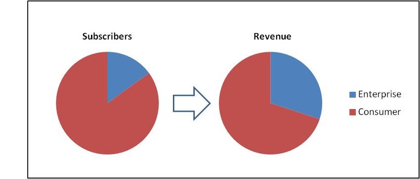
Employees of mid-to-large sized enterprises constitute 15% of subscribers at major mobile operators, and
contribute as much as 30% of their revenue. These enterprise customers are not only the most loyal and
profitable customers that mobile operators have, but also the most demanding. They expect the mobile
operator to deliver seamless wireless coverage in their facilities, to stay ahead of the rapidly growing
demand for wireless capacity, and to offer innovative ways to solve business problems.
Figure 1: Enterprise customers constitute 15% of subscribers, but generate 30% of revenues
Small cells offer one of the best ways for carriers to deliver wireless coverage and capacity, as well as
new services to customers. Analysts such as Gartner, Dell’Oro and Goldman Sachs expect small cells to
drive 18% of RAN investment by 2016. Infonetics Research expects enterprise small cells to be the
fastest growing small cell category, comprising over 50% of small cell investment by 2016.
Figure 2: Investment in small cells growing; expected to be 18% of RAN CapEx by 2016
© 2012 SpiderCloud Wireless, Inc. Public 3
‹
1
      ABI Research expects enterprise small cell equipment to reach the $2 billion mark by 2016 . Not only are
      enterprise small cells the only economically viable option to provide coverage in small to medium
      enterprises, they are expected to take market share from distributed antenna systems (DAS) in the mid-
      to-large enterprise market. The growth in enterprise small cell systems is primarily due to the system’s
      flexibility and ability to tie into an operator’s overall HetNet.

      Enterprise small cell systems cannot be built by merely increasing the transmit power and user count of
      residential small cells (also known as femtocells). Single high-power femtocells may be able to cover as
      much as 1,000-1,500 square meters. However, as Figure 3 shows, over 80% of commercial buildings are
      larger than 1,000 square meters, each with hundreds or sometimes, thousands of subscribers. These
      offices need multiple small cells for coverage and capacity.

              Figure 3: Distribution of Commercial Floor Space in the US; 80% above 1000 sq. meters

      The standard femtocell architecture (in which femtocells connect to a core-based gateway using a 3GPP
      defined protocol called Iuh) does not offer coordination, interference management or handovers between
      femtocells. Enterprise femtocell suppliers are approaching this problem by adding functionality to their
      femtocell gateways. Trials conducted by operators demonstrate that this approach does not scale. The
      largest commercially deployed enterprise small network that relies on a centrally located gateway for
      mobility and interference coordination has 7 small cells.

      SpiderCloud is solving the problem of deploying multiple small cells in an enterprise using its innovative
      Enterprise Radio Access Network (E-RAN) architecture consisting of Radio Nodes that are controlled by
      an Enterprise premises-based Services Node. This architecture has been designed from the ground up to
      address coordination, interference management and inter-small cell handovers. SpiderCloud’s largest
      enterprise deployment has 65 small cells, serves over 2,000 subscribers every day, and meets the key
      performance indicators (KPIs) demanded by one of the toughest operators in the world.

      1
          ABI Research, August 24, 2012: http://tinyurl.com/9o8gktv

© 2012 SpiderCloud Wireless, Inc.                          Public                                                  4

                                                                                                                       ‹
3. Design Considerations
      Mobile operators want to win or retain enterprise customers, and to sell them new services. To
      accomplish these goals, an in-building 3G wireless system should provide seamless voice coverage, with
      practically no call drops. Data throughput should be comparable to the LAN. A small cell system must be
      able to measure system performance and offer service level guarantees. The systems should be secure,
      easy to deploy and inexpensive to operate. Plus, it should easily integrate with the enterprise’s local
      network. This section discusses each of these design considerations in some detail.

           1. Seamless Mobility – Users in enterprise environments are not stationary. People are moving
              throughout the day in an enterprise. SpiderCloud’s experience shows that in a building with 800+
              subscribers, subscribers cross small cell boundaries over 20,000 times an hour.

                                          Handover Events Per Hour

                        20000

                        15000

                        10000

                         5000

                              0
                                    1    2       3       4         5      6       7        8

                 Figure 4: Handover events per hour in 9,000 sq. m. building with 800 subscribers

           2. Consistently high throughput – Customers are now accustomed to a multi-megabit data
              experience on their smartphones, and they will not be satisfied with an in-building wireless
              system unless it provides them such rates. Further, customers are unlikely to tolerate wide
              variations in data rates as they move throughout their offices.

           3. Enterprise-centered management – An operator should be able to manage each enterprise small
              cell system as one unit, rather than managing individual small cells. Not only does this reduce
              operational costs, it also allows the operator to differentiate by offering SLAs to its enterprise
              customers.

           4. Self-organizing and rapidly deployable – Speed of deployment is important, both for reducing
              deployment expenses and increasing revenue. Enterprise systems are often deployed after work
              hours when the operator (or enterprise) is paying overtime wages. Further, the sooner an
              operator can deploy, the sooner it can acquire new customers and start receiving revenue.

           5. Efficient use of Backhaul – Backhaul (the connection between the small cell system and the
              operator’s core network) is a very large recurring expense and must be minimized. To do so, all
              small cells in an enterprise should share a single backhaul link. Traffic on this link should be
              prioritized, and overhead minimized.

© 2012 SpiderCloud Wireless, Inc.                         Public                                                   5

                                                                                                                       ‹
6. Local switching of voice and data traffic – Enterprise users want to securely access their Intranet
              and PBX, without installing special client software. An enterprise small cell system should make
              this possible, without breaking basic features like mobility.

           7. Scalability – Since it is expensive for operators to commercialize new technologies, an ideal
              enterprise small cell system should be able to cost-effectively cover multi-story buildings and
              campuses that are as large as 50,000 square meters (500,000 square feet), or offices as small as
              1,000 square meters (10,000 square feet). Offices smaller than 1,000 square meters can be
              addressed by consumer or enterprise femtocells.

      4. Enterprise Small Cell Systems
      Broadly, there are two ways of building enterprise small cell systems.

           1. Using a core-network based controller: This approach, favored by residential femtocell
              companies, involves adding new functionality to the femtocell gateway (also known as Femto
              Concentrator, HNB gateway and Iuh gateway) to address basic requirements such as inter-small
              cell mobility and consistent throughput. There are three variants of this approach:

                     a. Enterprise femtocells with hard handover

                     b. Enterprise femtocells with soft handover (using Iurh)

                     c.   Picocells with soft handover (using Iub)

           2. Using a local controller in the enterprise: This approach, pioneered by SpiderCloud, uses a
              small controller in the enterprises that aggregates all the small cells in an enterprise, manages
              mobility and interference across them, integrates them with the enterprise’s Intranet, and provides
              a single interface to the core network.

      This section compares these two approaches based on the design considerations discussed earlier.

© 2012 SpiderCloud Wireless, Inc.                          Public                                                   6

                                                                                                                        ‹
4.1 Architectures with Core Network Based Controller
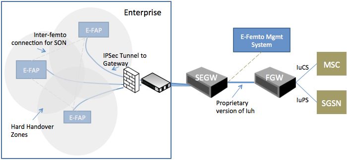
4.1.1 Enterprise Femtocells with Hard Handovers
Figure 5: Each Enterprise Femto Access Points (E-FAP) connects to a Femto Gateway (FGW)
This architecture is the logical evolution of the consumer femtocell architecture. Each enterprise femtocell
access point (E-FAP) implements 3G NodeB and RNC functionality, establishes an IPSec tunnel to a
security gateway in the core, and connects to a femtocell gateway behind it using proprietary versions of
the Iuh protocol. Within the enterprise, enterprise femtocells communicate with each other to implement
SON. Some vendors may secure this communication using IPSec or SSL.
This architecture has several limitations:
1. Seamless mobility – As shown in previous section, a building with 800 subscribers can have over
20,000 handovers per hour, or over 2.5 handover events per subscriber per hour. Since this
architecture supports inter-RNC hard handovers only, when a handset moves from the coverage
area of one E-FAP to another, its session has to be relocated from one E-FAP to another.
Significant amount of coverage overlap (as much as 30% in some solutions) is required to ensure
that calls are not dropped in this process. Still, hard handovers take long, which increases the
likelihood of dropped calls.
2. Consistent throughput – In order to prevent ping-ponging, users in hard handover zones stay
attached to their previous serving cell, even if it is weaker. Not only do these users get lower
HSDPA throughput than they could, these users increase uplink interference, and reduce the
2
HSUPA throughput available to all users. According to a paper published by Vodafone , users at
the cell edge in 3G systems with hard handover can see throughput degradation of 50% or more
compared to systems with soft handover.
2
Performance Evaluation of Soft Handover in a Realistic UMTS Network – Forkel, etal, Vodafone
© 2012 SpiderCloud Wireless, Inc. Public 7
‹
3. Backhaul – Each cell sets up one or more IPSec
This architecture is viable for tunnels to the security gateway. This makes it difficult to
few small cells in a building if prioritize traffic over the backhaul connection. If the operator
the end customer is willing to wants to use an enterprise’s existing LAN, it has to convince
the enterprise to punch a hole in the enterprise firewall for
tolerate call drops and does not each IPSec tunnel. Some vendors chose to get around this
need consistent throughput. problem by bringing a DSL line to every enterprise femtocell.
Locally switched voice and data
calls will be dropped if a user 4. Local Switching – Locally switched calls are dropped
moves from one femtocell to when a user moves from one small cell to another. There is
no way to maintain local IP addressing as the UE moves from
another. one small cell to another.
5. Backhaul – Each cell sets up one or more IPSec tunnels to the security gateway. This makes it
difficult to prioritize traffic over the backhaul connection. If the operator wants to use an enterprise’s
existing LAN, it has to convince the enterprise to punch a hole in the enterprise firewall for each
IPSec tunnel. Some vendors chose to get around this problem by bringing a DSL line to every
enterprise femtocell.
6. Local Switching – Locally switched calls are dropped when a user moves from one small cell to
another. There is no way to maintain local IP addressing as the UE moves from one small cell to
another.
7. Scalability – Since this architecture appears similar to that for consumer femtocells, it may work for a
small number of femtocells. Given the limitation identified above, it is unclear and considered unlikely
that this architecture can scale to more than 4 to 5 cells per cluster.
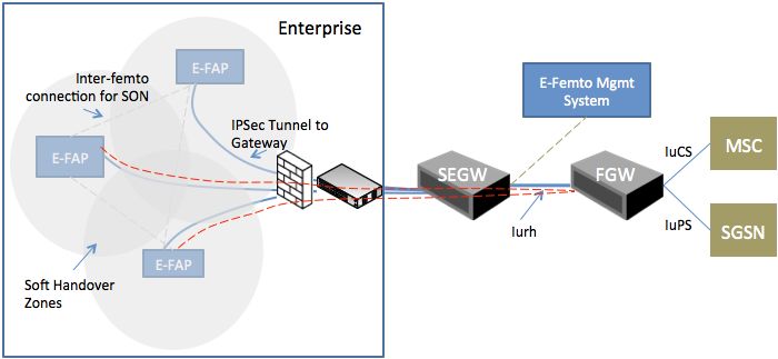
4.1.2 Enterprise Femtocells with Soft Handover
Figure 6: Soft Handover using Iurh, established through FGW. Dashed red line shows Iurh
connection during Soft Handover
© 2012 SpiderCloud Wireless, Inc. Public 8
‹This architecture addresses the main weakness of the architecture discussed in the previous section by
adding soft handover to enterprise femtocells. As before, each enterprise femtocell has NodeB and RNC
functionality. Soft handover is implemented using a new protocol called Iurh, a variant of the Inter-RNC
soft handover protocol, Iur, defined in 3GPP. This improves mobility performance but several key issues
remain:
1. Seamless Mobility – Iurh protocol enables soft handover between enterprise small cells and
address the well-known limitations of the hard handovers. Iurh adapts the Inter-RNC handover
interface (Iur) for Home NodeBs (HNB). During a handover event, the session state remains
anchored on the source HNB and the source HNB is responsible for forwarding traffic to one or
more target HNBs, often through the femtocell gateway. Since handsets can be in a state of soft
handover for very long periods of time, Iurh substantially increases backhaul traffic and the
processing power required of a small cell. In addition, all small cells in an Iurh-based system have
to be synchronized within 250 ppb. Iurh-based systems are still under development and have not
been trialed or deployed by any operator.
2. Consistent Throughput – Soft handover improves SNR at cell boundary and improves the cell
throughput at the cell edges. However, depending on the quality of the backhaul, there may be
delays in switching the serving cell. This could cause stalls in the data plane traffic.
3. Management – As seen in the figure above, each cell is a standalone network element and needs
to be individually managed. This complicates the process of collecting enterprise-centered
statistics, software image management and optimizing aggregate system performance.
4. Self Organizing – As with the architecture discussed in the previous section, topology discovery is
distributed and executed on an ad-hoc basis. This may not be as optimal as centralized SON
algorithms.
5. Backhaul – Each cell establishes one or
Enterprise femtocells can support more IPSec tunnels to the gateway. This limits
efficient utilization of a common backhaul as global
soft handover with Iurh, but requires COS/QOS based policing is encumbered.
more processing power per small
cell and more backhaul bandwidth. 6. Local Switching – Locally switched calls are
dropped when a user moves from one small cell to
Local switching will not work without another. There is no way to maintain local IP
breaking mobility. Scalability is addressing as the UE moves from one small cell to
another.
unknown because no Iurh systems
have been deployed. 7. Scalability – While the mobility issues are
partially addressed, many of the other issues remain.
It is unclear whether this architecture can scale to
more than a basic femto cluster of 5-7 cells.
© 2012 SpiderCloud Wireless, Inc. Public 9
‹4.1.3 Picocells with RNC in the Core
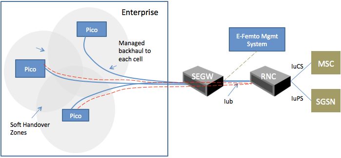
Figure 7: Picocells in Enterprise connect to RNC over managed backhaul; offer soft handover
In this architecture, each enterprise small cell is a pico Node B (or a picocell) and connects to a RNC in
the core network using the Iub interface. All user sessions are anchored at the RNC.
1. Seamless Mobility – This architecture can support soft handover between small cells as long as
the backhaul connection can support the tight latency and jitter constraints of the Iub interface.
2. Consistent Throughput – Anchoring all the sessions at a centralized RNC improves uplink and
downlink data performance. On the downlink, the RNC can serve users using the best available
cell. On the uplink, it can combine signals received at multiple cells. All UEs in the system can be
power-controlled.
3. Management – It is difficult to provide enterprise centered management. This complicates the
process of collecting enterprise-centered statistics, software image management and optimizing
aggregate system performance.
4. Self Organizing – Traditionally, picocells have not supported any form of self-organization and
require manual configuration. Picocells cannot implement ad-hoc SON (used by enterprise
femtocells) because they do not have radio resource management (RRM) functionality. RRM
functionality, in this architecture, resides in the centralized RNC, and typical centralized RNCs do
not implement SON.
© 2012 SpiderCloud Wireless, Inc. Public 10
‹5. Backhaul – This architecture places very stringent requirements over the backhaul link.
Traditionally, picocells are connected to RNCs over synchronous backhaul like T1/E1 links.
These links provide a low-latency and low-jitter connection, and frequency synchronization to
picocells. 50 ppb frequency synchronization is required between picocells for interference control
3 4
and soft handovers . In most commercial 3G networks, Iub link latency is below 10 ms .
To use picocells in an enterprise, a carrier must provision managed backhaul links to each
picocell that can meet stringent latency and jitter requirements. Further, these links should
provide a frequency reference (via IEEE 1588 v2), or an
Enterprise picocells use soft alternate frequency reference source (e.g. integrated
GPS, a local timing server in the enterprise) is required.
handover to offer seamless It is not clear how picocells can be deployed over an
mobility and interference enterprise Ethernet LAN.
coordination. However, this 6. Local switching of voice and data traffic – Local
architecture does not scale switching is not possible in this architecture because all
because it places very stringent user sessions are anchored at the RNC in the core
network. As such, it is not possible to create any new
requirements on backhaul and services or applications for enterprise customers.
does not allow SON. Local
switching is not possible 7. Scalability – This architecture is difficult to scale
because it does not support SON, and requires
because the RNC is in the core. dedicated backhaul links to each small cell. It is suitable
for deploying a handful of small cells inside enterprises.
3
“Synchronization Requirements for Cellular Networks over Ethernet”, IEEE 802.3 TS May 2009,
http://www.ieee802.org/3/time_adhoc/public/apr09/lee_01_0509.pdf
4
“Latency in HSDPA Data Networks”, QUALCOMM, “www.qualcomm.com/.../latency-in-hspa-data-
networks.pdf”
© 2012 SpiderCloud Wireless, Inc. Public 11
‹4.2 Enterprise Radio Access Network (E-RAN) Architecture
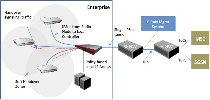
Figure 8: Enterprise Radio Access Network (E-RAN) Architecture with Local, Enterprise-based,
Controller
SpiderCloud’s E-RAN architecture, as shown above, includes a local, enterprise-based, Small Cell
Services Node (SN) to address the main requirements of building a scalable small cell network inside an
enterprise. The SN acts as the Radio Network Controller (RNC), Self Organizing Network (SON)
manager, and the cellular-enterprise integration gateway.
One of the biggest differences between E-RAN and femtocell-based architectures, discussed in sections
4.1.1 and 4.1.2, is that each E-RAN has a single Radio Network Controller (RNC), implemented within the
SN. All UE sessions are anchored on this RNC. As a result, a UE’s session does not have to be relocated
when it moves within the small cell network. The centralized RNC also manages interference between
radio nodes. It can simultaneously send voice traffic through multiple radio nodes, rapidly select the best
serving cell for HSDPA, and combine signals on the uplink. All these methods for managing inter-cell
interference have been proven in macro-cellular network, and SpiderCloud has optimized them for
operation inside buildings.
In addition to acting as the RNC, the SN also implements a SON manager. It is responsible for auto-
configuring, optimizing and managing the E-RAN. When a new small cell is added to the E-RAN, it
discovers the SN. From that point on, the SN takes responsibility for providing the small cell with its
software image and radio configuration. If a small cell goes out of service, the SN adjusts the
configuration of neighboring nodes to fill the coverage hole. All the complexity of configuring, managing
and optimizing scores of small cells stays hidden from the mobile operator’s core network.
In its role as a cellular-enterprise integration gateway, the SN authenticates enterprise users and, based
on policies, locally switches traffic from enterprise users to the Intranet. Local switching offloads the
operator’s core network, optimizes deployment of high-bandwidth applications like video telephony, and
© 2012 SpiderCloud Wireless, Inc. Public 12
‹enables 3G devices to access data that, because of regulatory reasons, cannot be sent over the mobile
operator’s network. Unlike controller-based architectures, local switching works even as users are moving
from one cell to another in the building.
An entire E-RAN system integrates with the core network using the standard Iuh interface – just like a
single consumer femtocell would. It does not require any extensions to Iuh (unlike architectures discussed
in 4.1.1 and 4.1.2).
This architecture provides a best-in-class performance across all facets of comparison:
1. Seamless Mobility – E-RAN architecture offers seamless mobility for voice and data sessions. All
UE sessions are anchored on the Services Node and do not have to be relocated as the UEs
moves throughout the building. Commercially deployed E-RAN systems handle more than
200,000 handover events each day, with call drop rates below 1%.
2. Consistent Throughput – E-RAN offers higher HSDPA and HSUPA throughout than enterprise
femtocells. Since all UE HSDPA sessions are anchored on the SN, the SN can serve each UE
from the best cell, increasing average HSDPA throughputs. On the uplink, the SN can combine
signals received at multiple cells. Smart power-control algorithms maximize diversity gains.
3. Management – E-RAN offers the operator with a single point of management for each enterprise
small cell system. It ensures that all radio nodes are running the same software image. Faults are
aggregated and correlated before they are forwarded to a management system in the core.
Performance counters are managed on a per-cell basis as well as for the entire system.
Operators can monitor and manage the performance of each enterprise small cell system, and
differentiate themselves by offering SLAs to large enterprise accounts.
4. Self Organizing – The E-RAN architecture enables centralized SON algorithms, geared toward
solving problems unique to deploying dozens of small cells in close proximity. These problems
range from discovering the topology of the network; reusing a small set (4-6) of primary
scrambling codes across as many as 75 radio nodes, and assigning neighbor lists to support soft
handover in the presence of pilot pollution. E-RAN SON algorithms continuously optimize system
performance based on UE measurements, adapt to changes in the macro network, as well as to
changes in the enterprise small cell network. SpiderCloud SON algorithms have been tested in a
wide range of buildings from low-rise buildings with open floor plans, multi-building campuses,
and high-rise buildings with large atriums.
5. Backhaul – E-RAN uses up to 30% less backhaul capacity than core-network controller based
architectures that implement soft handover (architectures discussed in sections 4.1.2 and 4.1.3).
All signaling and traffic related to handovers remains on the local network. A single backhaul
connection is established to the core, over which the SN can prioritize signaling, management,
and user traffic. By using less backhaul capacity than alternative architectures, E-RAN reduces a
carrier’s operating expense.
6. Local switching of voice and data traffic – Since all UE sessions are anchored at the SN, UE’s
can be locally switched to the enterprise voice and data network, without breaking inter-small cell
mobility. In fact, handover events are transparent to the local network. In addition, the SN
provides a centralized location for applying policies for local switching. The enterprise, or the
mobile operator, can create policies for which UEs should locally switch, and under what
conditions.
© 2012 SpiderCloud Wireless, Inc. Public 13
‹7. Scalability – The E-RAN architecture scales extremely well from few radio nodes to hundreds. SN
software can run a range of low-cost hardware platforms that allow E-RAN to be economically
viable for enterprises that have as few as 100 employees. On the other hand, it can be scaled up
to support thousands of subscribers.
The table below shows two real-world E-RAN deployments.
SpiderCloud - 1 SpiderCloud - 2
Building Size 9,000 m2 37,950 m2
Per Floor 3,000 m2 2,400 m2
Total Radio Nodes 18 65
Coverage per RN 500 m2 600 m2
Total subscribers per day 800 - 1,200 1,000 +
CS Voice sessions per day 2500 - 4,000 1,500 +
PS Data sessions per day 90,000 - 120,000 120,000 +
Installation Time 2 nights 1 week
E-RAN offers the most robust and scalable architecture for providing coverage, capacity
and services to enterprises. It offers seamless mobility and interference management
using soft handover, optimizes backhaul utilization, enables local switching of voice and
data, and provides enterprise-centered management. Finally, its self-organizing features
make it possible to offer service in very large enterprises in weeks, not months.
© 2012 SpiderCloud Wireless, Inc. Public 14
‹5. Conclusions
This document compares the performance of the various small-cell architectures for addressing the
needs of the market. A short summary is provided below:
Core Based Controller
Design Enterprise
Considerations Controller
Iuh Iurh Iub
Seamless Mobility Poor Good Good Excellent
Consistent
Poor Good Good Excellent
Throughput
Enterprise-
Centered Ad-hoc Ad-hoc Unknown Centralized
Management
Self-Organizing
Yes Yes No Yes
(SON)
Backhaul
Average Poor Poor Highest
Efficiency
No, if No, if
Not
Local Switching mobility mobility Yes
possible
is required is required
Scalability Low Unknown Low High
6. Appendix: Understanding Mobility in 3G Cellular Systems
Mobility is essential for cellular wireless systems. As a user moves through the system, its connection
must be migrated from one cell to another without interrupting voice or data traffic. This process is called
handover. Handovers can be hard (“break before make”) or soft (“make before break”). 3G systems
support both methods, but predominantly rely on soft handovers.
When a handset is in a state of soft handover, it has a connection with two more base stations. Not only
does soft handover eliminate the possibility of the handset ping-ponging between two base stations, it
also improves the signal-to-noise ratio (SNR) experienced by the handset at the cell edge. 3G systems
have a frequency reuse of one, and in the absence of soft handover, all cells except the serving cell of the
handset will appear as interference to it, drastically reducing SNR. Soft handover makes all cells above a
certain threshold a source of “signal” rather than interference, improving SNR. Higher SNR increases the
coverage area of 3G cells and 3G data throughput at the cell edge. In order to perform soft handover, the
call needs to be anchored at a single Radio Network Controller (RNC) in the network that can control the
multiple cells.
© 2012 SpiderCloud Wireless, Inc. Public 15
‹On the other hand, hard handovers are used when a handset crosses a RNC boundary, and there is no
connection between its old (source) RNC and the new (target) RNC. In this case, only a single cell is in
communication with the handset and, during handover, the call anchor needs to be relocated across the
RNCs through the core network. Hard handover results in discontinuities in voice and data traffic, and can
also result in undesirable tradeoffs between higher interference and higher call drop rates.
The figure below shows the three kinds of handovers implemented in a macro-cellular network.
1. Intra-RNC soft handover: A single modern radio network controller controls hundreds of base stations
that cover thousands of square kilometers. As a result, over 95% of all handovers in a 3G system are
Intra-RNC soft handovers.
2. Inter-RNC soft handover: Soft handovers can be conducted across RNC boundaries if RNC supports
a proprietary or standards-based Inter-RNC handover interface. The standards-based interface is known
as Iur. Typically, the call stays anchored at the RNC where it started, even if one of the legs in the
handover goes through another RNC.
3. Inter-RNC hard handover: Hard handover mechanisms are used in 3G systems on boundaries
between RNC from different infrastructure vendors, if these vendors do not support an inter-operable Iur
interface. Hard handovers are typically coordinated by MSCs and require careful planning of overlap
zones and hysteresis thresholds. Sometimes operators use different 5 MHz channels in handover zones
to minimize interference and increase the likelihood of successful handovers.
SpiderCloud Wireless is based in San Jose, California and is backed by investors Charles River Ventures, Matrix Partners, Opus Capital
and Shasta Ventures. For more information, follow the company on twitter at www.twitter.com/spidercloud_inc or visit www.spidercloud.com
SpiderCloud Wireless is a registered trademark and SmartCloud a trademark of SpiderCloud Wireless, Inc.
©2012 SpiderCloud Wireless, Inc. v092512
© 2012 SpiderCloud Wireless, Inc. Public 16
‹You can also read