EtherNet/IP Network Devices - User Manual Original Instructions - Literature Library
←
→
Page content transcription
If your browser does not render page correctly, please read the page content below

User Manual
Original Instructions

EtherNet/IP Network Devices
Important User Information
Read this document and the documents listed in the additional resources section about installation, configuration, and
operation of this equipment before you install, configure, operate, or maintain this product. Users are required to
familiarize themselves with installation and wiring instructions in addition to requirements of all applicable codes, laws,
and standards.

Activities including installation, adjustments, putting into service, use, assembly, disassembly, and maintenance are
required to be carried out by suitably trained personnel in accordance with applicable code of practice.

If this equipment is used in a manner not specified by the manufacturer, the protection provided by the equipment may
be impaired.

In no event will Rockwell Automation, Inc. be responsible or liable for indirect or consequential damages resulting from
the use or application of this equipment.

The examples and diagrams in this manual are included solely for illustrative purposes. Because of the many variables and
requirements associated with any particular installation, Rockwell Automation, Inc. cannot assume responsibility or
liability for actual use based on the examples and diagrams.

No patent liability is assumed by Rockwell Automation, Inc. with respect to use of information, circuits, equipment, or
software described in this manual.

Reproduction of the contents of this manual, in whole or in part, without written permission of Rockwell Automation,
Inc., is prohibited

Throughout this manual, when necessary, we use notes to make you aware of safety considerations.

                 WARNING: Identifies information about practices or circumstances that can cause an explosion in a hazardous
                 environment, which may lead to personal injury or death, property damage, or economic loss.

                 ATTENTION: Identifies information about practices or circumstances that can lead to personal injury or death, property
                 damage, or economic loss. Attentions help you identify a hazard, avoid a hazard, and recognize the consequence.

  IMPORTANT      Identifies information that is critical for successful application and understanding of the product.

Labels may also be on or inside the equipment to provide specific precautions.

                 SHOCK HAZARD: Labels may be on or inside the equipment, for example, a drive or motor, to alert people that dangerous
                 voltage may be present.

                 BURN HAZARD: Labels may be on or inside the equipment, for example, a drive or motor, to alert people that surfaces may
                 reach dangerous temperatures.

                 ARC FLASH HAZARD: Labels may be on or inside the equipment, for example, a motor control center, to alert people to
                 potential Arc Flash. Arc Flash will cause severe injury or death. Wear proper Personal Protective Equipment (PPE). Follow ALL
                 Regulatory requirements for safe work practices and for Personal Protective Equipment (PPE).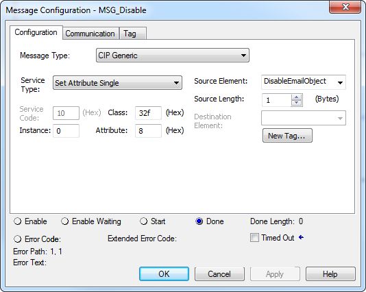
Table of Contents
Table of Contents                     Preface . . . . . . . . . . . . . . . . . . . . . . . . . . . . . . . . . . . . . . . . . . . . . . . . . . . . . . . .5
                                      Additional Resources . . . . . . . . . . . . . . . . . . . . . . . . . . . . . . . . . . . . . . . . . . . 5

                                      Chapter 1
EtherNet/IP Features in Allen-        EtherNet/IP Device-Specific Features. . . . . . . . . . . . . . . . . . . . . . . . . . . . 8
Bradley Network Devices               Duplicate IP Address Detection . . . . . . . . . . . . . . . . . . . . . . . . . . . . . . . . 10
                                          Duplicate IP Address Resolution. . . . . . . . . . . . . . . . . . . . . . . . . . . . 10
                                      IP Address Swapping . . . . . . . . . . . . . . . . . . . . . . . . . . . . . . . . . . . . . . . . . . 11
                                      DNS Addressing . . . . . . . . . . . . . . . . . . . . . . . . . . . . . . . . . . . . . . . . . . . . . . 11
                                      Socket Interface . . . . . . . . . . . . . . . . . . . . . . . . . . . . . . . . . . . . . . . . . . . . . . . 12
                                      Linear Network . . . . . . . . . . . . . . . . . . . . . . . . . . . . . . . . . . . . . . . . . . . . . . . 12
                                      Device Level Ring . . . . . . . . . . . . . . . . . . . . . . . . . . . . . . . . . . . . . . . . . . . . . 13
                                      Parallel Redundancy Protocol . . . . . . . . . . . . . . . . . . . . . . . . . . . . . . . . . . 14
                                      EtherNet/IP Network Specifications . . . . . . . . . . . . . . . . . . . . . . . . . . . 14
                                      Time Synchronization . . . . . . . . . . . . . . . . . . . . . . . . . . . . . . . . . . . . . . . . . 16

                                      Chapter 2
Configure a Workstation to            Configure the Ethernet Communication Driver in RSLinx Classic
Operate on an EtherNet/IP             Software . . . . . . . . . . . . . . . . . . . . . . . . . . . . . . . . . . . . . . . . . . . . . . . . . . . . . . 19
                                      Configure the USB Communication Driver in RSLinx Classic Software
Network
                                      21

                                      Chapter 3
Set an IP Address                     Set the IP Address with the BOOTP/DHCP Utility . . . . . . . . . . . . .                                           25
                                          Disable BOOTP/DHCP with RSLinx Classic Software . . . . . .                                                    28
                                          DHCP Considerations . . . . . . . . . . . . . . . . . . . . . . . . . . . . . . . . . . . .                    29
                                      Set the IP Address with RSLinx Classic Software. . . . . . . . . . . . . . . . .                                   30
                                          Configure Port Settings with RSLinx Classic Software . . . . . . . .                                           32
                                      Set the IP Address with Studio 5000 Logix Designer Application. .                                                  34
                                      Reset the IP Address to Factory Default Value . . . . . . . . . . . . . . . . . . .                                35

                                      Chapter 4
Configure the Device                  Add the Device to the Controller Organizer . . . . . . . . . . . . . . . . . . . . .                               37
                                      Configure EtherNet/IP Communication. . . . . . . . . . . . . . . . . . . . . . . .                                 38
                                      Produced and Consumed Data . . . . . . . . . . . . . . . . . . . . . . . . . . . . . . . . .                       39
                                      Message Instructions . . . . . . . . . . . . . . . . . . . . . . . . . . . . . . . . . . . . . . . . . .           39

                                 Rockwell Automation Publication ENET-UM006A-EN-P - March 2019                                                                   3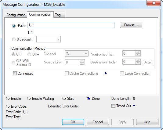
Table of Contents

                         Chapter 5
Send Email               EtherNet/IP Communication Module as an Email Client . . . . . . . . 41
                         Send Email Via a Controller-initiated Message Instruction. . . . . . . . 43
                            Create String Tags . . . . . . . . . . . . . . . . . . . . . . . . . . . . . . . . . . . . . . . . 43
                            Enter the Ladder Logic. . . . . . . . . . . . . . . . . . . . . . . . . . . . . . . . . . . . . 48
                            Configure the MSG Instruction That Identifies the Mail Relay
                            Server. . . . . . . . . . . . . . . . . . . . . . . . . . . . . . . . . . . . . . . . . . . . . . . . . . . . . 48
                            Configure the MSG Instruction That Contains the Email Text 50
                            Configure the Email Object . . . . . . . . . . . . . . . . . . . . . . . . . . . . . . . . 52
                         Possible Email Status Codes . . . . . . . . . . . . . . . . . . . . . . . . . . . . . . . . . . . . 58

                         Index . . . . . . . . . . . . . . . . . . . . . . . . . . . . . . . . . . . . . . . . . . . . . . . . . . . . . . . .59

4                   Rockwell Automation Publication ENET-UM006A-EN-P - March 2019
Preface
This manual describes how to use EtherNet/IP communication modules in
Logix 5000™ control systems.
Make sure that you are familiar with the following:
• Use of a controller in a Logix 5000 control system, including these
following controllers:
– CompactLogix™ 5380 controllers
– Compact GuardLogix® 5380 controllers
– CompactLogix 5480 controller
– ControlLogix® 5580 controllers
– GuardLogix® 5580 controllers
• Use of an EtherNet/IP network
• Use of various software applications from Rockwell Automation
Additional Resources These documents contain more information concerning related products from
Rockwell Automation.
Table 1 - Additional Resources
Resource Description
EtherNet/IP Media Planning and Describes how to use the required media components and how to
Installation Manual plan for, install, verify, troubleshoot, and certify your EtherNet/IP
network.
This manual is available from the Open DeviceNet Vendor Association
(ODVA) at: http://www.odva.org.
Ethernet Design Considerations Reference Describes basic Ethernet concepts:
Manual, publication ENET-RM002
EtherNet/IP Socket Interface Application Describes the socket interface that you can use to program MSG
Technique, publication ENET-AT002 instructions to communicate between a Logix 5000™ controller and
Ethernet devices. In this case, the interface is used because the
Ethernet devices that do not support the EtherNet/IP application
protocol. Such devices include barcode scanners, RFID readers, or
other standard Ethernet devices.
EtherNet/IP Embedded Switch Technology Describes how to install, configure, and maintain linear and Device
Application Guide, publication ENET-AP005 Level Ring (DLR) networks by using Rockwell Automation® EtherNet/
IP devices that are equipped with embedded switch technology.
EtherNet/IP Parallel Redundancy Protocol Describes how you can configure a Parallel Redundancy Protocol
Application Technique, (PRP) network with the 1756-EN2TP EtherNet/IP communication
publication ENET-AT006 module and a Stratix® 5400 or 5410 switch.
Integrated Architecture and CIP Sync Provides information on CIP Sync and the IEEE 1588-2008 Precision
Configuration Application Technique, Time Protocol.
publication IA-AT003
Integrated Motion on the EtherNet/IP Reference descriptions of the AXIS_CIP_DRIVE attributes and the
Network Reference Manual, publication Studio 5000 Logix Designer® application Control Modes and Methods
MOTION-RM003
Electronic Keying in Logix 5000 Control Describes how to use electronic keying in Logix 5000 control system
Systems Application Technique, applications.
publication LOGIX-AT001
Rockwell Automation Publication ENET-UM006A-EN-P - March 2019 5Preface
Table 1 - Additional Resources
Resource Description
Network Technology webpage, Provides information on reference architectures and white papers on
http://www.rockwellautomation.com/ networking.
rockwellautomation/products-
technologies/network-technology/
overview.page?
Industrial Automation Wiring and Provides general guidelines for installing a Rockwell Automation®
Grounding Guidelines, publication industrial system.
1770-4.1
Product Certifications website, Provides declarations of conformity, certificates, and other
http://www.rockwellautomation.com/ certification details.
rockwellautomation/certification/
overview.page
You can view or download publications at
http://www.rockwellautomation.com/literature/. To order paper copies of
technical documentation, contact your local Allen-Bradley distributor or
Rockwell Automation sales representative.
6 Rockwell Automation Publication ENET-UM006A-EN-P - March 2019Chapter 1
EtherNet/IP Features in Allen-Bradley Network
Devices
Topic Page
EtherNet/IP Device-Specific Features 8
Duplicate IP Address Detection 10
IP Address Swapping 11
DNS Addressing 11
Socket Interface 12
Linear Network 12
Device Level Ring 13
Parallel Redundancy Protocol 14
EtherNet/IP Network Specifications 14
Time Synchronization 16
EtherNet/IP networks offer a comprehensive suite of messages and services for
many automation applications. This open network standard uses standard
Ethernet communication products to support real-time I/O messaging,
information exchange, and general messaging. Other features to all EtherNet/
IP network devices include the following:
• Support for messaging, produced/consumed tags, and distributed I/O
• DNS addressing
• Internet Group Management Protocol (IGMP) snooping (enabled by
default) and querier (disabled by default)
• Port configuration and diagnostics
• Email server
EtherNet/IP networks also support CIP Safety applications. Such support
makes the simultaneous transmission of safety and standard control data and
diagnostics information over a common network possible.
Rockwell Automation Publication ENET-UM006A-EN-P - March 2019 7Chapter 1 EtherNet/IP Features in Allen-Bradley Network Devices
EtherNet/IP Device-Specific EtherNet/IP network devices can provide the following functionality. See the
user manual for your device for details.
Features
• Support for the following communication rates:
– 10 Mbps
– 100 Mbps
– 1 Gbps
IMPORTANT • When a device uses the 1 Gbps network communication rate, it
supports only full-duplex mode.
• When a device uses the 10 Mbps or 100 Mbps network
communication rate, it supports full-duplex and half-duplex
mode.
• Linear network
• Device Level Ring protocol
• Option to operate as a Ring supervisor on a DLR network
• Parallel Redundancy Protocol
• Duplicate IP address detection
• Socket interface
• Email client
8 Rockwell Automation Publication ENET-UM006A-EN-P - March 2019EtherNet/IP Features in Allen-Bradley Network Devices Chapter 1
Figure 1 shows how Rockwell Automation® EtherNet/IP network devices fit
into a control system. In this example, the following can occur over the
EtherNet/IP network:
• Controllers produce and consume tags
• Controllers initiate MSG instructions that send and receive data
• Control of I/O modules
• Use of Integrated Motion over an EtherNet/IP network
• Workstations configure devices, and upload or download projects to the
controllers
Figure 1 - EtherNet/IP Network Devices in a Control System
Star Topology 5069-L340ERM Controller
Distributed I/O
Compact 5000™ I/O Modules
DC INPUT DC OUTPUT ANALOG INPUT ANALOG OUTPUT ANALOG OUTPUT
PanelView™ 5500 Terminal 5069-IB16 5069-OB16 5069-IY4 5069-OF8 5069-OF8
Logix5585E
SAFETY ON
REM
NET
LINK
Logix5584ES
REM
NET
LINK
LNK1 LNK2 NET OK
RUN PROG RUN PROG
MOD Power
1
2
SA Power
ControlLogix® Controllers
ControlLogix I/O Modules
Workstation
1794-AENT Adapter
FLEX™ I/O Modules
002 1734-AENTR
POINT I O
Module
Status
Switch
Network
Activity
Network
Status
1734-AENTR
Point Bus
Link 1 Status
Activity/
Status System
Power DC INPUT DC OUTPUT ANALOG INPUT ANALOG OUTPUT COUNTER
Field
Power
FWD
IP ADDRESS
ENET LINK
EtherNet/IP 5069-IB16 5069-OB16 5069-IY4 5069-OF8 5069-HSC2xOB4
Link 2
Activity/
Status
POINT I/O™ Modules
PowerFlex® 525 5094-AENTR Adapter
Drive Compact 5000™ I/O
FLEX 5000™ I/O Modules
5069-AENTR Adapter
Compact 5000™ I/O
Modules
Workstation
DLR Topology 1783-ETAP DC INPUT DC OUTPUT ANALOG INPUT ANALOG OUTPUT ANALOG OUTPUT
5069-IB16 5069-OB16 5069-IY4 5069-OF8 5069-OF8
5069-L340ERM Controller
MOD Power
Compact 5000™ I/O Modules
Kinetix® 5700
SA Power
Servo Drive
PanelView™ 5500 Terminal
1756-EN4TR
1756 I/O Modules
002 1734-AENTR
POINT I O
Module
Status
Network
Activity
Network
Status
Point Bus
Link 1 Status
Activity/
Status System
Power
Field
DC INPUT DC OUTPUT ANALOG INPUT ANALOG OUTPUT COUNTER Power
IP ADDRESS
5069-IB16 5069-OB16 5069-IY4 5069-OF8 5069-HSC2xOB4
Link 2
Activity/
Status
1734-AENTR Adapter
Compact 5000™ I/O
5094-AENTR Adapter POINT I/O™ Modules
FLEX 5000™ I/O Modules
5069-AENTR Adapter
Compact 5000 I/O Modules
Rockwell Automation Publication ENET-UM006A-EN-P - March 2019 9Chapter 1 EtherNet/IP Features in Allen-Bradley Network Devices
Duplicate IP Address Duplicate IP address detection verifies that an IP address does not match any
other device IP address on the network when you perform either of these tasks:
Detection
• Connect the device to a EtherNet/IP network.
• Change the IP address on the device.
If the IP address matches that of another device on the network, the
EtherNet/IP port on the device transitions to conflict mode. In conflict mode,
these conditions exist:
• OK status indicator blinks red.
• Network (NET) status indicator is solid red.
• If the device has a text display, the following message scrolls across the 4-
character display:
Duplicate IP -
For example: 10.88.60.196 Duplicate IP - 00:00:BC:02:34:B4
Duplicate IP Address Resolution
This table describes how to resolve duplicate IP addresses.
Duplicate IP Address Detection Conditions Resolution Process
• Both devices support duplicate IP address detection 1. The device that began operation first uses the IP address and continues to operate without interruption.
• Second device is added to the network after the first 2. The device that begins operation second detects the duplication and enters Conflict mode.
device is operating on the network
• Both devices support duplicate IP address detection Both EtherNet/IP devices enter Conflict mode.
• Both devices were powered up at approximately the To resolve this conflict, follow these steps:
same time a. Assign a new IP address to one of the devices.
b. Cycle power to the other device or disconnect and reconnect all Ethernet cables from the other device.
One device supports duplicate IP address detection and a 1. Regardless of which device obtained the IP address first, the device that does not support IP address detection
second device does not uses the IP address and continues to operate without interruption.
2. The device that supports duplicate IP address detection detects the duplication and enters Conflict mode.
10 Rockwell Automation Publication ENET-UM006A-EN-P - March 2019EtherNet/IP Features in Allen-Bradley Network Devices Chapter 1
DNS Addressing To qualify the device address further, use DNS addressing to specify a host
name for a device. When you specify a host name for the device, you also
specify a domain name and DNS servers. DNS addressing makes it possible to
create similar network structures and IP address sequences under different
domains.
DNS addressing is necessary only if you refer to the device by host name, such
as in path descriptions in MSG instructions.
To use DNS addressing, follow these steps.
1. Assign a host name to the device.
A network administrator can assign a host name. Valid host names must
be IEC-1131-3 compliant.
2. Configure the device IP address:
In the DNS server, the host name must match the IP address of
the device.
IMPORTANT Make sure the DNS enable bit is set.
• If you use Logix Designer application, version 28 or later, to configure
your device, the enable bit is set and DNS addressing is successful.
• If you use RSLinx® Classic software, version 2.41.00 or later, to
configure your device, the enable bit is cleared and DNS addressing
fails.
Rockwell Automation Publication ENET-UM006A-EN-P - March 2019 11Chapter 1 EtherNet/IP Features in Allen-Bradley Network Devices
3. In the Logix Designer application, add the device to the I/O.
IMPORTANT If a child device resides in the same domain as its parent device, type the
host name. If the domain name of the child device differs from its parent
device, type the host name and the domain name (host.domain)
IMPORTANT You can also use DNS addressing in a device profile in the I/O
configuration tree or in a message path. If the domain name of the
destination device differs from the source device, use a fully qualified
DNS name (hostname.domainname). For example, to send a message
from AEN2TR1.location1.companyA to AEN2TR1.location2.company, the
host names match, but the domains differ. Without the entry of a fully
qualified DNS name, the device adds the default domain name to the
specified host name.
Socket Interface Some EtherNet/IP devices support the use of a CIP Generic MSG instruction
to request socket services. For more information, see EtherNet/IP Socket
Interface Application Technique, ENET-AT002.
Linear Network A linear network is a collection of devices that are daisy-chained together. The
EtherNet/IP embedded switch technology lets you implement this topology at
the device level. No additional switches are required.
Figure 2 - Example Linear Network
00:00:BC:2E:69:F6
1 (Front)
2 (Rear)
U
V
W
2
1
The following are advantages of a linear network.
• Simple installation
• Reduced wiring and installation costs
• No special software configuration required
• Improved CIP Sync application performance on linear networks
The primary disadvantage of a linear network is that any break of the cable
disconnects all devices downstream from the break from the rest of the
network.
12 Rockwell Automation Publication ENET-UM006A-EN-P - March 2019EtherNet/IP Features in Allen-Bradley Network Devices Chapter 1
Device Level Ring Device Level Ring (DLR) is an EtherNet/IP protocol that is defined by the
Open DeviceNet® Vendors’ Association (ODVA). DLR provides a means to
detect, manage, and recover from single faults in a ring-based network.
A DLR network includes the following types of ring nodes.
Node Description
Ring supervisor A ring supervisor provides these functions:
• Manages traffic on the DLR network
• Collects diagnostic information for the network
A DLR network requires at least one node to be configured as ring supervisor.
IMPORTANT: By default, the supervisor function is disabled on supervisor-capable
devices, so they are ready to participate on a linear or star network or as a ring node on a
DLR network.
In a DLR network, you must configure at least one of the supervisor-capable devices as
the ring supervisor before physically connecting the ring. If you do not, the DLR network
does not work.
Ring participants Ring participants provide these functions:
• Process data that is transmitted over the network.
• Pass on the data to the next node on the network.
• Report fault locations to the active ring supervisor.
When a fault occurs on the DLR network, ring participants reconfigure themselves and
relearn the network topology.
Redundant gateways Redundant gateways are multiple switches that are connected to one DLR network and
(optional) also connected together through the rest of the network.
Redundant gateways provide DLR network resiliency to the rest of the network.
Depending on their firmware capabilities, both devices and switches can
operate as supervisors or ring nodes on a DLR network. Only switches can
operate as redundant gateways.
For more information about DLR, see the EtherNet/IP Device Level Ring
Application Technique, publication ENET-AT007.
Rockwell Automation Publication ENET-UM006A-EN-P - March 2019 13Chapter 1 EtherNet/IP Features in Allen-Bradley Network Devices
Parallel Redundancy Parallel Redundancy Protocol (PRP) is defined in international standard
IEC 62439-3 and provides high-availability in Ethernet networks. PRP
Protocol technology creates seamless redundancy by sending duplicate frames to two
independent network infrastructures, which are known as LAN A and LAN B.
A PRP network includes the following components.
Component Description
LAN A and LAN B Redundant, active Ethernet networks that operate in parallel.
Double attached node (DAN) An end device with PRP technology that connects to both LAN A and LAN B.
Single attached node (SAN) An end device without PRP technology that connects to either LAN A or LAN B.
A SAN does not have PRP redundancy.
Redundancy box (RedBox) A switch with PRP technology that connects devices without PRP technology to
both LAN A and LAN B.
Virtual double attached node An end device without PRP technology that connects to both LAN A and LAN B
(VDAN) through a RedBox.
A VDAN has PRP redundancy and appears to other nodes in the network as a DAN.
Infrastructure switch A switch that connects to either LAN A or LAN B and is not configured as a RedBox.
For more information about PRP topologies and configuration guidelines, see
the EtherNet/IP Parallel Redundancy Protocol Application Technique,
publication ENET-AT006.
EtherNet/IP Network
Specifications
Table 2 - EtherNet/IP Network Specifications
Cat. No. Connections CIP Unconnected Ethernet Node Packet Rate Capacity (packets/second)(5) SNMP
Messages Count, Max Support
TCP CIP (backplane + I/O HMI and MSG (password
Ethernet) required)
1734-AENT, 1734-AENTR 32 20 32 — 5000 900 No
1738-AENT, 1738-AENTR 32 20 32 — 5000 900 No
1756-ENBT 64 128(3) 64 + 64 — 5000 900 Yes
1756-EN2F, 1756-EN2T, 128 256(3) 128 + 128 — IMPORTANT: Packet rates 2000 Yes
1756-EN2TXT, 1756-EN2TR, for ControlLogix EtherNet/IP
1756-EN2TRXT communication modules
depend on series and
1756-EN2TSC 128 256(3) 128 + 128 — firmware revision. 930 with encryption Yes
1800 without
encryption
1756-EN3TR 128 256(3) 128 + 128 — 2000 Yes
1756-EN4TR, 1756-EN4TRXT 512 1000 I/O 256+256 — • 50,000 without CIP • 3,700 without CIP Yes
528 (4) Security Security
• 25,000 with integrity • 2,700 with integrity
• 15,000 with integrity and • 1,700 with integrity
confidentiality and confidentiality
1756-EWEB 64 128(3) 128 + 128 — — 900 Yes
1756-L81E 512 — — 100 — — —
1756-L82E 512 — — 175 — — —
14 Rockwell Automation Publication ENET-UM006A-EN-P - March 2019EtherNet/IP Features in Allen-Bradley Network Devices Chapter 1
Table 2 - EtherNet/IP Network Specifications (continued) (continued)
Cat. No. Connections CIP Unconnected Ethernet Node Packet Rate Capacity (packets/second)(5) SNMP
Messages Count, Max Support
TCP CIP (backplane + I/O HMI and MSG (password
Ethernet) required)
1756-L83E 512 — — 250 — — —
1756-L84E 512 — — 250 — — —
1756-L85E 512 — — 300 — — —
1768-ENBT 32(1) 64 (3)
32 + 32 — 5000 960 Yes
64(2) 128
1769-L3xE 64 32(3) 32 + 32 — 4000 760 Yes
1769-L16ER-BB1B, 1769- 120 256 256 4 6000 @ 500 bytes/packet 400 messages/s @ 20% Yes
L18ER-BB1B, 1769-L18ERM- comm. timeslice
BB1B
1769-L24ER-QB1B, 1769- 120 256 256 8 6000 @ 500 bytes/packet Yes
L24ER-QBFC1B
1769-L27ERM-QBFC1B 120 256 256 16 6000 @ 500 bytes/packet Yes
1769-L30ER, 1769-L30ERM, 120 256 256 16 6000 @ 500 bytes/packet Yes
1769-L30ER-NSE
1769-L33ER, 1769-L33ERM 120 256 256 32 6000 @ 500 bytes/packet Yes
1769-L36ERM 120 256 256 48 6000 @ 500 bytes/packet Yes
1783-ETAP, 1783-ETAP1F, 64 — — — — 900 No
1783-ETAP2F
1794-AENT 64 64 — — 9500 — Yes
5069-AENRT 32 16 16 — 100000 500 Yes
(messaging)
5069-AEN2TR 256 32 — 100000 2000 Yes
(messaging)
5094-AENTR, 5094-AENTRXT, 32 16 16 — 100000 500 Yes
5094-AEN2TR, 5094- (messaging)
AEN2TRXT
5069-L306ER, 512 — 256 16 128000 2000 Yes
5069-L306ERM
5069-L310ER, 512 — 256 24 128000 2000 Yes
5069-L310ER-NSE,
5069-L310ERM
5069-L320ER, 512 — 256 40 128000 2000 Yes
5069-L320ERM
5069-L330ER, 512 — 256 60 128000 2000 Yes
5069-L330ERM
5069-L340ER, 512 — 256 90 128000 2000 Yes
5069-L340ERM
5069-L350ERM 512 — 256 120 128000 2000 Yes
5069-L380ERM 512 — 256 150 128000 2000 Yes
5069-L3100ERM 512 — 256 180 128000 2000 Yes
9300-ENA — — — — — — —
(1) The 1768-ENBT communication module supports 32 TCP connections with firmware revision 1.
(2) The 1768-ENBT communication module supports 64 TCP connections with firmware revision 2 or later.
(3) CIP connections can be used for all explicit or all implicit applications. For example, a 1756-ENBT module has a total of 128 CIP connections that can be used for any combination of connections.
Rockwell Automation Publication ENET-UM006A-EN-P - March 2019 15Chapter 1 EtherNet/IP Features in Allen-Bradley Network Devices
(4) There are 1000 CIP I/O connections and 528 CIP messaging connections.
(5) Total packet rate capacity = I/O Produced Tag, max + HMI/MSG, max. Packet rates vary depending on packet size. For more detailed specifications, see the EDS file for a specific catalog number.
Reserve 10% of the bandwidth (packets/second) of the network device for
Explicit Messaging.
Time Synchronization In certain situations, the I/O modules can synchronize with the adapter before
the adapter synchronizes with the system Grandmaster clock. This
synchronization occurrence leads to a time difference between the I/O and the
Grandmaster clock until the adapter synchronizes with the Grandmaster clock.
In your logic, verify that the adapter is synchronized with the Grandmaster
clock (CIPSyncValid) before you initiate time stamp requests or scheduled
outputs from your I/O modules. A system with intermediate devices, such as
network bridges and switches, can require that you insert a delay until the time
stabilizes in the system.
For information on how to verify that the adapter is synchronized to a
Grandmaster clock, see CIP Sync Diagnostics in the Integrated Architecture
and CIP Sync Configuration Application Technique, publication IA-AT003.
This publication also includes information on Time Sync Object Attributes.
16 Rockwell Automation Publication ENET-UM006A-EN-P - March 2019Chapter 2
Configure a Workstation to Operate on an
EtherNet/IP Network
Topic Page
Configure the Ethernet Communication Driver in RSLinx Classic Software 19
Configure the USB Communication Driver in RSLinx Classic Software 21
Before you can connect to the device via an Ethernet cable, you must install an
EtherNet/IP driver on your workstation.
A communication driver is required to complete these tasks:
• Upload and download Logix Designer application projects to
Logix 5000™ controllers over an EtherNet/IP network
• Collect controller data for electronic operator interfaces, for example,
PanelView™ Plus terminals, and visualization software, for example,
FactoryTalk® View software
• Update device firmware
• Set or change the IP address.
• Configure the device
Rockwell Automation Publication ENET-UM006A-EN-P - March 2019 17Chapter 2 Configure a Workstation to Operate on an EtherNet/IP Network
Remember the following when you use the RSLinx® Classic software
communication drivers:
• EtherNet/IP driver:
– Supports runtime communications
– Requires that the workstation is properly connected to the
EtherNet/IP network
– Supports communications over longer distances when compared to
the USB driver
• Ethernet devices driver:
– Requires that you configure the IP addresses to which the software
browses and, therefore, the devices with which the device
communicates
• USB driver:
– Convenient method to connect to an unconfigured device and
configure the Ethernet port
– Convenient method to connect to a device when the Ethernet port
configuration is unknown
– Convenient method to update the device firmware
– Not intended for runtime connections; it is a temporary-use only
connection with a limited cabling distance
18 Rockwell Automation Publication ENET-UM006A-EN-P - March 2019Configure a Workstation to Operate on an EtherNet/IP Network Chapter 2
Configure the Ethernet Before you add an Ethernet driver, confirm that these conditions exist:
Communication Driver in • The workstation is properly connected to the EtherNet/IP network.
RSLinx Classic Software
• The workstation IP address and other network parameters are
configured correctly.
To configure the EtherNet/IP driver, follow these steps.
1. From the Communications menu, choose Configure Drivers.
The Configure Drivers dialog box appears.
2. From the Available Driver Types pull-down menu, choose
EtherNet/IP Driver.
3. Click Add New.
The Add New RSLinx® Driver dialog box appears.
4. Type a name for the new driver and click OK.
Rockwell Automation Publication ENET-UM006A-EN-P - March 2019 19Chapter 2 Configure a Workstation to Operate on an EtherNet/IP Network
The Configure driver dialog box appears.
5. Click Browse Local Subnet.
TIP To view devices on another subnet or VLAN from the workstation running
RSLinx Classic software, click Browse Remote Subnet.
6. Select the desired driver, and click OK.
The new driver is available on the Configure Drivers dialog box.
7. Click Close.
20 Rockwell Automation Publication ENET-UM006A-EN-P - March 2019Configure a Workstation to Operate on an EtherNet/IP Network Chapter 2
Configure the USB In RSLinx Classic software, version 3.80.00 or later, a USB driver
automatically appears in the software when you connect the USB cable from
Communication Driver in your workstation to the controller.
RSLinx Classic Software
The USB driver can take a moment to appear in RSLinx Classic software.
IMPORTANT EtherNet/IP drivers remain visible in RSLinx Classic software after they are
configured regardless of whether they are in use or not.
A USB driver appears in RSLinx Classic software only when a USB cable is
connected between the workstation and the controller.
Once the cable is disconnected, the driver disappears from RSLinx
Classic software.
ATTENTION: The USB port is intended for temporary, local programming
purposes only and is not intended for permanent connection. The USB cable
is not to exceed 3.0 m (9.84 ft) and must not contain hubs.
WARNING: Do not use the USB port in hazardous locations.
IMPORTANT Do not simultaneously load firmware for multiple devices through a USB
port. If you do, one or more of the firmware loads can fail in the middle of
the loading process.
If you use the RSLinx Classic software, version 3.80.00 or later, and a USB
driver does not appear automatically, complete the following steps.
1. Connect one end of the USB cable to your workstation, and the other
end to the USB port on the device.
The RSLinx Found New Hardware Wizard dialog box appears.
2. Click Install the software automatically (recommended).
Rockwell Automation Publication ENET-UM006A-EN-P - March 2019 21Chapter 2 Configure a Workstation to Operate on an EtherNet/IP Network
3. Click Next.
These dialog boxes appear consecutively.
4. Click Finish.
22 Rockwell Automation Publication ENET-UM006A-EN-P - March 2019Configure a Workstation to Operate on an EtherNet/IP Network Chapter 2
5. In RSLinx Classic software, from the Communications menu,
click RSWho.
The RSLinx Workstation organizer appears, and your device appears
under two different drivers, a virtual chassis and the USB port.
Virtual Chassis Driver
USB Port Driver
Rockwell Automation Publication ENET-UM006A-EN-P - March 2019 23Chapter 2 Configure a Workstation to Operate on an EtherNet/IP Network Notes: 24 Rockwell Automation Publication ENET-UM006A-EN-P - March 2019
Chapter       3

                                   Set an IP Address

                                    Topic                                                                  Page
                                    Set the IP Address with the BOOTP/DHCP Utility                         25
                                    Set the IP Address with RSLinx Classic Software                        30
                                    Set the IP Address with Studio 5000 Logix Designer Application         34
                                    Reset the IP Address to Factory Default Value                          35

Set the IP Address with the        The BOOTP/DHCP tool is a standalone server that you can use to set an IP
                                   address. The BOOTP/DHCP tool sets an IP address and other Transport
BOOTP/DHCP Utility                 Control Protocol (TCP) parameters.

                                   You can use the BOOTP/DHCP tool to set the IP address when the device
                                   powers up in the out-of-box state. That is, the rotary switches are not set to a
                                   valid IP address, and the device is DHCP enabled.

                                   Access the BOOTP/DHCP tool from one of these locations:

                                        • Programs > Rockwell Software > BOOTP-DHCP Tool >
                                          BOOTP-DHCP Tool

                                        • Tools directory on the Studio 5000® environment installation CD

                                                IMPORTANT             Before you start the BOOTP/DHCP tool, remember the following:
                                                                      • Make sure that you have the hardware (MAC) address of
                                                                         the device.
                                                                         The hardware address is on a sticker on the side of the device
                                                                         and has a format similar to the following:
                                                                          00-00-BC-14-55-35

                                                                      • Make sure that the workstation that you use to set the IP address
                                                                        has only one connection to the EtherNet/IP network on which
                                                                        the device resides.
                                                                        The BOOTP/DHCP tool can fail to work if your workstation has
                                                                        multiple connections to the EtherNet/IP network.

                              Rockwell Automation Publication ENET-UM006A-EN-P - March 2019                                               25
Chapter 3 Set an IP Address
To set the IP address with BOOTP/DHCP tool, complete the following steps.
1. Confirm that the device is connected to the network.
2. Start the BOOTP-DHCP tool.
The MAC ID of the device appears in the Request History window.
3. Select the appropriate device and click Add to Relation List.
The New Entry dialog box appears.
4. Type an IP address, Hostname, and Description for the device.
Hostname and Description are optional.
5. Click OK.
6. To assign this configuration on the device, wait for the device to appear
in the Relation List panel and select it.
26 Rockwell Automation Publication ENET-UM006A-EN-P - March 2019Set an IP Address Chapter 3
7. Click Disable BOOTP/DHCP.
The device now uses the assigned configuration and does not issue BOOTP or
DHCP requests after power is cycled on the controller.
IMPORTANT Remember the following:
• If you do not click Disable BOOTP/DHCP, on future power cycles, the
current IP configuration is cleared and the controller sends DHCP
requests again.
• If you click Disable BOOTP/DHCP and it does not disable BOOTP/DHCP,
you can use RSLinx® Classic software to disable BOOTP/DHCP.
For more information on how to use RSLinx Classic software to disable
BOOTP/DHCP, see page 28.
Rockwell Automation Publication ENET-UM006A-EN-P - March 2019 27Chapter 3 Set an IP Address
Disable BOOTP/DHCP with RSLinx Classic Software
To disable BOOTP/DHCP in RSLinx Classic software, complete the
following steps.
1. Start RSLinx Classic software.
After several seconds, an RSWho dialog box appears.
2. If no RSWho dialog box appears, from the Communications pull-down
menu, choose RSWho.
3. Navigate to the device.
You can access the device via the USB or an EtherNet/IP driver.
4. Right-click on the device and choose Module Configuration.
5. Click the Port Configuration tab.
6. Click Manually configure IP settings.
28 Rockwell Automation Publication ENET-UM006A-EN-P - March 2019Set an IP Address Chapter 3
7. Click OK.
DHCP Considerations
If the device is DHCP-enabled in the out-of-box condition, you can use a
DHCP server to set the IP address.
The DHCP server automatically assigns IP addresses to client stations logging
on to a TCP/IP network. DHCP is based on BOOTP and maintains some
backward compatibility.
ATTENTION: You can use a DHCP server that is always configured to assign
the same IP address to specific devices when they appear on the EtherNet/
IP network and request an IP address.
If your system does not use a DHCP server that assigns the same IP address for
specific devices, we strongly recommend that you assign the device a fixed
IP address. Do not set the IP address dynamically. That is, do not use the Obtain
IP settings automatically by using DHCP.
When a device uses Obtain IP settings automatically by using DHCP, the IP
address for that device is cleared with each power cycle. If the same IP address
is not automatically assigned to the device when it requests a new IP address,
the device can be assigned another IP address than what was used before
cycling power.
The use of a new IP address can result in such issues as a Duplicate IP address
condition or configuration faults because the IP address differs from what is
stored in a Logix Designer application project.
Failure to observe this precaution can result in unintended machine motion or
loss of process control.
Rockwell Automation Publication ENET-UM006A-EN-P - March 2019 29Chapter 3 Set an IP Address
Set the IP Address with To use RSLinx Classic software to set the IP address for the first time, after it
powers up in the out-of-box state, you must connect to the device via the USB
RSLinx Classic Software port.
If the device does not have a USB port, you cannot use RSLinx Classic
software to set the IP address for the first time the device powers up in the out-
of-box state.
IMPORTANT You can use RSLinx Classic software to configure the device, including to
change the IP address after it has been set.
To change the IP address by using the RSLinx Classic software, the rotary
switches on the device must be set to positions that are valid for DHCP
address configuration (000...254).
You must access the device by browsing to it via an EtherNet/IP driver.
For more information on how to configure a device with RSLinx Classic
software, see page 32.
WARNING: Do not use the USB port in hazardous locations.
ATTENTION: The USB port is intended for temporary local programming
purposes only and not intended for permanent connection. The USB cable is
not to exceed 3.0 m (9.84 ft) and must not contain hubs.
Complete these steps to set the IP address with RSLinx Classic software when
the device is in the out-of-box state.
1. Confirm that your computer is connected to the device via a USB cable.
2. Start the RSLinx Classic software.
After several seconds, an RSWho dialog box appears.
3. If the RSWho dialog box does not appear, from the Communications
pull-down menu, choose RSWho.
4. Right-click the device and choose Module Configuration.
30 Rockwell Automation Publication ENET-UM006A-EN-P - March 2019Set an IP Address Chapter 3
The Module Configuration dialog box appears.
5. Click the Port Configuration tab.
6. Click Manually configure IP settings and set the port configuration
parameters.
7. Click OK.
8. Open the USB branch on the menu tree.
Rockwell Automation Publication ENET-UM006A-EN-P - March 2019 31Chapter 3 Set an IP Address
The device shows the IP address.
Configure Port Settings with RSLinx Classic Software
You can use RSLinx Classic software to configure a subset of the parameters
available on the device.
Complete the following steps.
1. Right-click the device and then click Module Configuration.
2. Click the Advanced Port Configuration tab.
32 Rockwell Automation Publication ENET-UM006A-EN-P - March 2019Set an IP Address Chapter 3
IMPORTANT Consider the following when you configure the port settings:
• When the device uses the 1 Gbps network communication rate, it supports only full-duplex mode.
• When the device uses the 10 Mbps or 100 Mbps network communication rate, it supports full-duplex and half-duplex
mode.
• The speed and duplex settings for the devices on the same Ethernet network must be the same to avoid transmission errors.
• Fixed speed and full-duplex settings offer better reliability than autonegotiate settings and are recommended for some
applications.
• If the device is connected to an unmanaged switch, leave Auto-negotiate checked or the device fails.
• If you force the port speed and duplex with a managed switch, the corresponding port of the managed switch must be
forced to the same settings or the device fails.
• If you connect a manually configured device to an autonegotiate device (duplex mismatch), a high rate of transmission
errors can occur.
• To disable a port, clear the Enable checkbox.
You cannot disable both ports on a 5069-AENTR or FLEX 5000 EtherNet/IP adapter simultaneously in RSLinx Classic
software. We recommend that before you disable a port, you confirm that the port is not in use.
• If you disable a port in RSLinx Classic software and the port is being used for network communication, the communication is
interrupted.
In this case, if the other Ethernet port is enabled, we recommend that you moved the Ethernet cable from the disabled port
and connect it to the enabled port.
After you re-enable the port that was unintentionally disabled, you can change the cable connection back to the first port
Task Action
Let the device automatically set the Leave the Auto-negotiate enabled.
port speed and duplex settings.
Manually configure the port speed Follow these steps.
and duplex settings.
1. Clear the Auto-negotiate port speed and duplex checkbox.
2. From the Current Port Speed pull-down menu, choose a port speed.
3. From the Current Duplex pull-down menu, choose full-duplex.
3. On the Module Configuration dialog box, click OK.
Rockwell Automation Publication ENET-UM006A-EN-P - March 2019 33Chapter 3 Set an IP Address
Set the IP Address with To use the Logix Designer application to set the IP address of the device, follow
these steps.
Studio 5000 Logix Designer
Application 1. In the Controller Organizer, right-click the device and choose
Properties.
The Module Properties dialog box appears.
2. Click the Port Configuration tab.
3. In the IP address field, type the IP address.
4. In the other fields, type the other network parameters, if needed.
IMPORTANT The fields that appear vary from one device to another.
5. Click Set.
6. Click OK.
34 Rockwell Automation Publication ENET-UM006A-EN-P - March 2019Set an IP Address Chapter 3
Reset the IP Address to You can reset the IP address of the device to its factory default value with the
following methods:
Factory Default Value
• If the device has rotary switches, set the switches to 888 and cycle power.
• If the device does not have rotary switches, use an MSG instruction to
the reset the IP address.
Rockwell Automation Publication ENET-UM006A-EN-P - March 2019 35Chapter 3 Set an IP Address Notes: 36 Rockwell Automation Publication ENET-UM006A-EN-P - March 2019
Chapter     4

                             Configure the Device

                              Topic                                                     Page
                              Add the Device to the Controller Organizer                37
                              Configure EtherNet/IP Communication                       38
                              Produced and Consumed Data                                39
                              Message Instructions                                      39

                             After installing a device and setting the IP address, add the device to the
                             Controller Organizer in a programming software project. This addition
                             establishes I/O control.

                             You must download that project to the host controller before operation can
                             begin. When the controller begins operation, it establishes a connection with
                             the device. The configuration of the device determines its behavior.

Add the Device to the        To build the I/O configuration for a typical I/O network, follow these steps.
Controller Organizer            1. Add the device.
                                2. Add the remote device for distributed I/O.
                                3. Add the I/O modules.

                             This graphic shows the I/O configuration of the consumer controller after
                             distributed I/O modules are added.

                        Rockwell Automation Publication ENET-UM006A-EN-P - March 2019                        37
Chapter 4 Configure the Device
Configure EtherNet/IP To configure the device, follow these steps.
Communication 1. Make sure that the device is installed, started, and connected to the
controller.
2. In the Controller Organizer, right-click the device and choose
Properties.
The Module Properties dialog box appears.
3. Make configuration selections on the individual tabs.
4. Click OK.
38 Rockwell Automation Publication ENET-UM006A-EN-P - March 2019Configure the Device Chapter 4
Produced and Consumed Logix controllers can produce (broadcast) and consume (receive) system-
shared tags that are sent and received via the device. Produced and consumed
Data tags each require connections.
Tag Type Required Connections
Produced The local controller (producing) must have one connection for the produced tag
and the first consumer and one more connection for each additional consumer
(heartbeat). The produced tag requires two connections.
As you increase the number of controllers that can consume a produced tag, you
also reduce the number of connections the controller has available for other
operations. Example operations include communication and I/O.
Consumed Each consumed tag requires one connection for the controller that is consuming
the tag.
IMPORTANT: When you configure a consumed tag, you must add a remote
device to the programming software project for the producing controller to
configure the consuming controller. The default Comm Format when adding a
remote device to the project is rack-optimized.
Change the Comm Format to None when adding the remote device.
All EtherNet/IP devices support as many as 32 produced multicast
connections. Each tag that passes through an EtherNet/IP device uses one
connection. Due to this feature, the number of available connections limits the
total number of tags that can be produced or consumed. If the device uses all of
its connections for I/O and other devices, no connections remain for produced
and consumed tags.
IMPORTANT Depending on whether it is producing or consuming a tag, a Logix 5000™
controller uses its connections differently.
For more information, see Logix 5000 Controllers Produced and Consumed
Tags Programming Manual, publication 1756-PM011.
Message Instructions Messages transfer data to other devices, such as other controllers or operator
interfaces. Each message uses one connection, regardless of how many devices
are in the message path. To conserve connections, you can configure one
message to read from or write to multiple devices.
For more information on programming MSG instruction, see the Logix 5000™
Controller General Instructions Reference Manual, publication 1756-RM003.
Rockwell Automation Publication ENET-UM006A-EN-P - March 2019 39Chapter 4 Configure the Device Notes: 40 Rockwell Automation Publication ENET-UM006A-EN-P - March 2019
Chapter          5

                             Send Email

                             This chapter describes how to send an email through an EtherNet/IP
                             communication module.

                              Topic                                                                                          Page
                              EtherNet/IP Communication Module as an Email Client                                            41
                              Send Email Via a Controller-initiated Message Instruction                                      43
                              Possible Email Status Codes                                                                    58

                             For email, the EtherNet/IP communication module can be remote or local to
                             the controller.

EtherNet/IP Communication    The EtherNet/IP communication module is an email client that uses a mail
                             relay server to send email.
Module as an Email Client
                                   IMPORTANT             The EtherNet/IP communication module can send an email to only one
                                                         recipient at a time. The module cannot mail to a distribution list.

                             Table 3 - Ethernet Email
                               Desired Action                                             Required Tasks
                               Send an email to specific personnel when a controller      Program the controller to send an MSG instruction to the
                               application generates an alarm or reaches a certain        EtherNet/IP communication module
                               condition                                                  The MSG instruction then instructs the
                                                                                          EtherNet/IP communication module to send the email
                               Send controller or application status information          text (contained within the MSG instruction) to the mail
                               regularly to a project manager                             relay server.
                                                                                          Multiple controllers can use the same EtherNet/IP
                                                                                          communication module to initiate email.

                        Rockwell Automation Publication ENET-UM006A-EN-P - March 2019                                                            41
Chapter 5 Send Email
The EtherNet/IP communication module sends only the content of an MSG
instruction as an email to a mail relay server. Delivery of the email depends on
the mail relay server. The EtherNet/IP communication module does not
receive email.
Figure 3 - Sample System
ControlLogix®5580 Controller With 1756-ENBT, 1756-EN2F, 1756-EN2T,
1756-EN2TR, 1756-EN2TXT, 1756-EN3TR, or 1756-EN4TR Module
Firewall/Router Logix5575 Redundancy Module EtherNet/IP
10/100 BASE T
EtherNet/IP ControlNet EtherNet/IP ControlNet
RUN FORCE SD OK
PRI COM OK LNK1 LNK2 OK LNK NET OK LNK NET OK
REM PR
RUN OG
1 2
Ethernet Switch Mail Relay
Server
Ethernet Switch
CompactLogix 5380 Controller
Table 4 - Sample System Capabilities
Device Capability
ControlLogix controller Send an MSG instruction to the 1756-ENBT module to initiate sending an
email to the mail relay server.
CompactLogix controller Use the path of the MSG instruction to identify the 1756-ENBT module as the
target of the MSG instruction.
ControlLogix 5580 Controller Send an email to the mail relay server from the email interface on the Send an
Email link.
This interface requires that you enter all email information.
Mail relay server Send email to specified recipients.
The mail relay server determines the delivery of any email that is sent
through an EtherNet/IP communication module, whether via an MSG
instruction or from its built-in interface.
42 Rockwell Automation Publication ENET-UM006A-EN-P - March 2019Send Email Chapter 5
Send Email Via a Controller- A Logix controller can send a generic CIP message instruction to the
EtherNet/IP communication module that instructs the module to send an
initiated Message email message to an SMTP mail relay server that uses the standard SMTP
Instruction protocol. This process automatically communicates controller data and
application conditions to appropriate personnel.
IMPORTANT Be careful to write the ladder logic to be sure the MSG instructions are
not continuously triggered to send email messages.
Some mail relay servers require a domain name be provided during the initial
handshake of the SMTP session. For these mail relay servers, specify a domain
name when configuring the network settings of the EtherNet/IP
communication module.
Create String Tags
You need three controller-scoped string tags. Each tag performs one of
these functions:
• Identifies the mail server
• Contains the email text
• Contains the status of the email transmission
The default STRING data type supports up to 82 characters. In most cases,
this limit is sufficient to contain the address of the mail server. For example, to
create tag EmailConfigstring of type STRING, follow these steps.
1. Right-click on the Strings tab to create a New String Type.
The default STRING data type in the programming software is not
large enough for most email text.
Rockwell Automation Publication ENET-UM006A-EN-P - March 2019 43Chapter 5 Send Email
2. Create the String Type “EmailString”.
IMPORTANT An email message must not exceed 474 characters in length. An
additional 4-byte string-length value is added to the tag. As a
result, the maximum source length is 478 characters.
3. Create the tag names by toggling between the Monitor Tags and Edit
Tags tabs shown in the following image.
44 Rockwell Automation Publication ENET-UM006A-EN-P - March 2019Send Email Chapter 5
4. Enter a controller tag for the Email Configuration String.
5. Edit the newly created tag, and select the data type.
6. Type the IP address or host name of the mail server.
7. Click OK.
Rockwell Automation Publication ENET-UM006A-EN-P - March 2019 45Chapter 5 Send Email
8. Create one controller-scoped tag, such as EWEB_EMAIL, of this new
data type to contain the email text.
9. Create a second controller-scoped tag, such as EmailDstStr, of this new
data type to contain the transmission status.
Both of these tags are of type EmailString.
10. Set the Email Distribution String Tag to “1”.
11. Click ... in the Value column of the Controller Tags dialog box
46 Rockwell Automation Publication ENET-UM006A-EN-P - March 2019Send Email Chapter 5
12. Type your email.
Use the string browser to type the text of the email. To include To:,
From:, and Subject: fields in the email, use symbols to
separate each of these fields. The To: and From fields are required; the
Subject: field is optional. For example:
To: Email address of recipient
From: Email address of sender
Subject: subject of message
body of email message
The text of the email does not have to be static. You can program a
controller project to collect specific data to be sent in an email.
13. Click OK
For more information on how to use ladder logic to manipulate string data, see
the Logix 5000™ Controllers Common Procedures Programming Manual,
publication 1756-PM001.
Rockwell Automation Publication ENET-UM006A-EN-P - March 2019 47Chapter 5 Send Email
Enter the Ladder Logic
Ladder logic requires two MSG instructions. One MSG instruction configures
the mail server and must be executed only once. The second MSG instruction
triggers the email. Execute this email MSG instruction as often as needed.
SetServer
The first rung configures the mail server. The second rung sends the email text.
Configure the MSG Instruction That Identifies the Mail Relay Server
To configure the MSG instruction that identifies the mail relay server, follow
these steps.
1. In the MSG instruction, click the Communication tab.
48 Rockwell Automation Publication ENET-UM006A-EN-P - March 2019Send Email Chapter 5
2. In the Path field, type the path for the MSG instruction. The path starts
with the controller initiating the MSG instruction.
Type the number of the port from which the message exits and the
address of the next module in the path.
For example, if the EtherNet/IP communication module is in the same
chassis as the controller and is in slot 2, the path is: 1, 2.
For more information on how to configure the path of an MSG
instruction, see the Logix 5000 Controllers General Instructions
Reference Manual, publication 1756-RM003.
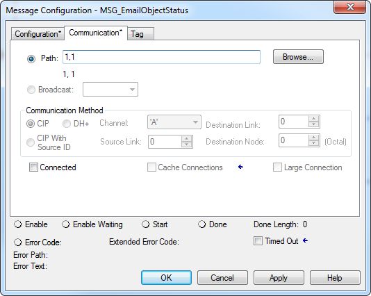
3. Click the Configuration tab.
4. Configure the MSG parameters for sending an email.
• From the Service Type pull-down menu, choose Attribute Single
• In the Instance field, type 1.
• In the Class field, type 32f.
• In the Attribute field, type 5.
• From the Source Element pull-down menu, choose the tag that
contains your email text.
• In the Source Length field, type the number of characters in the email
plus four.
In this example, you would enter 13 for the number of characters plus
4 for a total of 17.
The Source Length is the number of characters in the STRING tag
that identifies the mail relay server plus 4 characters.
In this example, the tag contains 13 characters.
After the MSG instruction that configures the mail relay server executes
successfully, the controller stores the mail relay server information in
nonvolatile memory. The controller retains this information, even
through power cycles, until another MSG instruction changes the
information.
Rockwell Automation Publication ENET-UM006A-EN-P - March 2019 49Chapter 5 Send Email
Configure the MSG Instruction That Contains the Email Text
To configure the MSG instruction that contains the email text, perform this
procedure.
1. Click the Configuration tab.
The Source Length is the number of characters in the email tag plus 4
characters.
In this example, the email text contains 65 characters.
2. Configure the MSG parameters for sending an email.
• From the Service Type pull-down menu, choose Custom.
• In the Service Code field, type 4b.
• In the Instance field, type 1.
• In the Class field, type 32f.
• In the Attribute field, type 0.
• From the Source Element pull-down menu, choose the tag that
contains your email text.
• In the Source Length field, type the number of characters in the email
plus four.
In this example, you would enter 65 for the number of characters plus
4 for a total of 69.
• From the Destination pull-down menu, choose a tag to contain the
status of your email transmission.
The Source Length is the number of characters in the STRING tag
that identifies the mail relay server plus 4 characters.
In this example, the tag contains 65 characters.
50 Rockwell Automation Publication ENET-UM006A-EN-P - March 2019You can also read