ETVision Instruction Manual - Argus Science
←
→
Page content transcription
If your browser does not render page correctly, please read the page content below
ETVision
Instruction Manual
    MANUAL VERSION 3.3
        October 2021

                       techsupport@argusscience.com
                       Web site: www.argusscience.com
ETVISION MANUAL

                                                       Table of Contents
1      INTRODUCTION AND GENERAL SYSTEM DESCRIPTION ...................................................................4

2      ENVIRONMENTAL AND SAFETY CONSIDERATIONS ...........................................................................5
    2.1        Statement on Safety Levels of Infrared Illumination ..................................................................................... 5
    2.2        Compliance .................................................................................................................................................... 5
    2.3        Safety Disclaimer...........................................................................................................................................5
3      SYSTEM COMPONENTS .................................................................................................................................7
    3.1        ETVision Wearable Optics ............................................................................................................................. 7
    3.2        ETVision Controller .......................................................................................................................................9
    3.3        ETVision PC ................................................................................................................................................ 10
4      INTERCONNECTIONS ................................................................................................................................... 11

5      ABBREVIATED INSTRUCTIONS ................................................................................................................. 16

6      EYE TRACKING BASICS ............................................................................................................................... 17

7      BASIC SYSTEM OPERATION....................................................................................................................... 19
    7.1    Charge Controller battery ............................................................................................................................ 19
    7.2    Connect Controller to Wearable Optics Unit ............................................................................................... 19
    7.3    Establish communication between Controller and ETVision application .................................................... 20
      7.3.1     Boot up Controller ............................................................................................................................... 20
      7.3.2     Run the ETVision Application on the ETVision PC ........................................................................... 20
    7.4    Position wearable optics unit on participant ................................................................................................ 22
    7.5    Calibrate participant..................................................................................................................................... 25
      7.5.1     Auto Calibration .................................................................................................................................. 25
      7.5.2     Single Point Manual Calibration ......................................................................................................... 27
      7.5.3     Adding Calibration Points if Needed ................................................................................................... 28
    7.6    Monitor gaze data and system status ........................................................................................................... 31
      7.6.1     Status Indicators .................................................................................................................................. 31
      7.6.2     Left Eye and Right Eye windows ........................................................................................................ 31
      7.6.3     Scene Image window ........................................................................................................................... 33
      7.6.4     Data Display window.......................................................................................................................... 34
      7.6.5     Window Control ................................................................................................................................... 35
      7.6.6     Manual offset correction ...................................................................................................................... 36
      7.6.7     Monitor Battery Charge....................................................................................................................... 36
      7.6.8     Audio .................................................................................................................................................... 37
    7.7    Record data .................................................................................................................................................. 39
      7.7.1     Record gaze data directly on ETV PC ................................................................................................. 39
      7.7.2     Record video/audio data on micro SD card ......................................................................................... 42
      7.7.3     Compute gaze data from an SD card file ............................................................................................. 45
    7.8    Communicate in real-time with an external device...................................................................................... 47
      7.8.1     Connecting to ETVision with ETRemote .............................................................................................. 49
      7.8.2     Connecting to ETVision with a user created application .................................................................... 51
    7.9    External (“Stationary”) Scene Camera ........................................................................................................ 52
8      USING ETVISION SYSTEM OUTDOORS .................................................................................................... 55

9      APPENDICIES .................................................................................................................................................. 57

                                                                                       2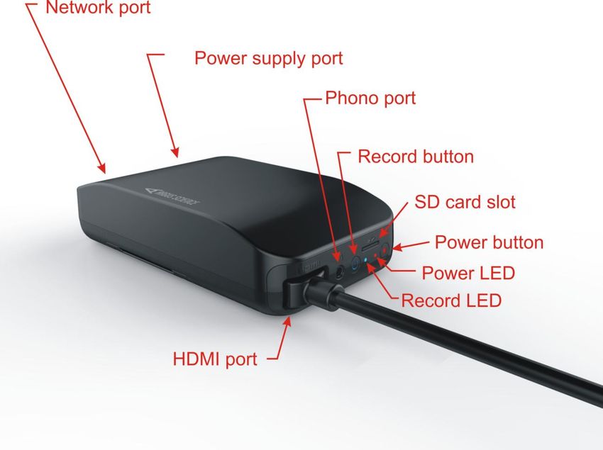
ETVISION MANUAL
9.1 Appendix A -- LED color codes .................................................................................................................. 57
9.2 Appendix B – Manual Calibration function details ..................................................................................... 59
9.3 Appendix C -- ETVision recorded and transmitted Data items .................................................................... 61
9.3.1 Data Item List ...................................................................................................................................... 61
9.3.2 Data Item Explanation ......................................................................................................................... 63
9.4 Appendix D – System Control Table settings and Default values ............................................................... 66
9.4.1 Eye Data tab ........................................................................................................................................ 66
9.4.2 Video Source tab .................................................................................................................................. 67
9.4.3 Subject Calibration tab ........................................................................................................................ 69
9.4.4 System Configuration tab..................................................................................................................... 69
9.4.5 About Tab ............................................................................................................................................ 72
9.5 Appendix E -- Minimum specifications for ETVision PC and software installation instructions ................ 73
9.5.1 PC specifications ................................................................................................................................. 73
9.5.2 ETVision software installation ............................................................................................................. 73
9.6 Appendix F – Removing HDMI cable from wearable optics ...................................................................... 75
9.7 Appendix G -- SD Card Selection & Preparation ........................................................................................ 76
9.8 Appendix H – Eye camera rotation adjustment ........................................................................................... 77
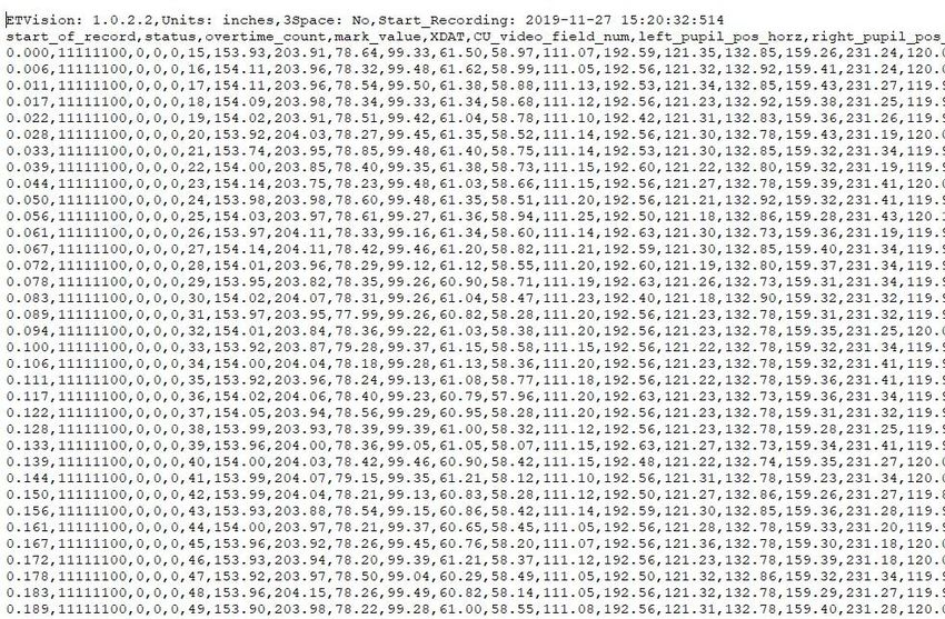
9.9 Appendix I – Recording ETVision data in text (csv) format ........................................................................ 78
9.10 Appendix J -- ETVision Sunshield Attachment ........................................................................................... 80
3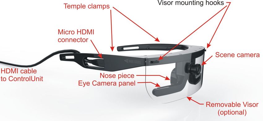
ETVISION MANUAL

1 Introduction and General System Description
ETVision (ETV) is a lightweight wearable system for measuring binocular point of gaze 180 times per
second.

The wearable unit resembles an eyeglasses frame that can be worn by itself or over the participant’s
prescription eyeglasses. It contains miniature “eye cameras” that view each eye and a “scene camera”
that views the scene in front of the participant, and a microphone. An optional visor can be mounted
to front of the headgear.

A cable extending from the earpiece connects to a small Controller (slightly larger than a smart phone)
that easily fastens to an adjustable belt or can be held by the participant (or near the participant) in
some other way. The Controller holds a mico SD card for video and audio data recording, and
includes a rechargeable battery. It can also be powered directly from a DC power supply.

The ETVision system also includes a laptop PC that connects to the Controller in real-time via a LAN
cable or via WiFi. Alternately, the PC can read video and audio data from a microSD card previously
recorded by the wearable Controller. Note that by using the WiFi connection or recording to an SD
card for later data processing, the subject can be completely un-tethered while data recording takes
place.

An application running on the laptop PC uses the video images from the wearable cameras to compute
point-of-gaze with respect to a scene camera coordinate frame. The laptop can record the digital gaze
coordinates 180 times per second. This digital file also includes pupil diameter of each eye, and can
optionally include upper and lower eyelid positions, blink information, and other feature detection
measurements used as part of gaze computation.

In addition to recording a digital file, the PC application shows a real time display of the eye and scene
camera images and records these as wmv type video files. The 1280x720p scene image updates 30
times per second and includes a superimposed cursor showing the participant’s point of gaze in the
scene image. The scene video also includes audio from the head gear mic or a local mic. The eye
camera video displays include superimposed outlines and crosshairs to show proper recognition by the
system of eye image features.

The laptop PC can stream the 180 Hz, real-time, digital data to external devices via LAN, or stream
the real-time video scene image to external devices via LAN.

The Argus Science ETAnalysis application, usually included with the basic system, can be used to
play back and analyze gaze data recorded with ETVision. Detailed instructions for use of the
ETAnalysis application are provided in a separate manual.

An optional addition to the basic system, called ET3Space, uses head position and orientation data
from one of several third party motion tracking devices to compute gaze with respect to a room fixed
coordinate system and to determine point-of-gaze on multiple surfaces in the environment. This
optional feature is described in a separate manual.

                                                    4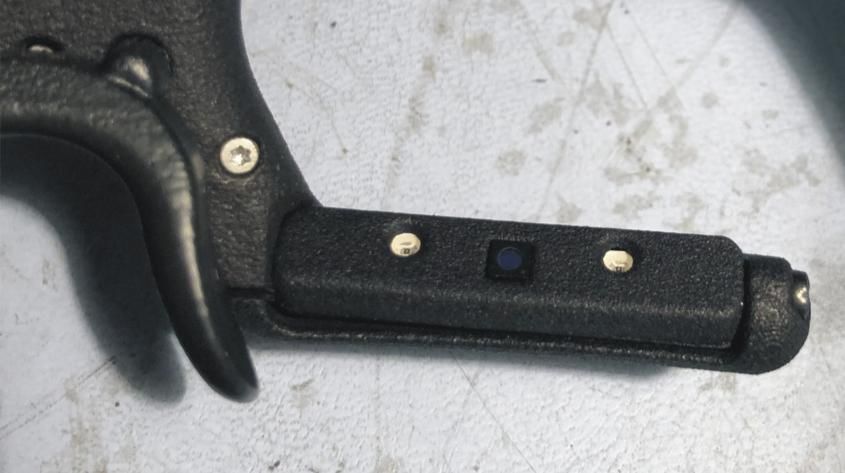
ETVISION MANUAL

2 Environmental and Safety Considerations
2.1 Statement on Safety Levels of Infrared Illumination
One of the most comprehensive and authoritative sources on the subject of light source safety is a
handbook entitled Safety with Lasers and Other Optical Sources, by David Sliney and Myron
Wolbarsht, first published in 1980 by Plenum Press. Quoting from page 147 of this book, “safe
chronic ocular exposure values, particularly to IR-A, probably are of the order of 10 mW/cm² or
below”. “IR-A” refers to the spectral band between 760 and 1400 nanometers, the range that includes
the Argus ETVision LEDs.

We are aware of no data, made available since the book was published, that would challenge this
conclusion. Most people might wish to be more conservative than the figure cited above, and the
ETVision illumination is at least an order of magnitude below this level. The largest irradiance value
that will be produced with the Argus ETVision optics is 0.75 mW/cm² (@ 870nm wavelength), at the
plane of the eye.

ETVison uses non-coherent illumination. There are no lasers in the headgear.

2.2 Compliance
This device complies with Part 15 of the FCC Rules and complies with Industry Canada license-
exempt RSS standards. Operation is subject to the following two conditions:
   1. This device may not cause harmful interference, and
   2. This device must accept any interference received, including interference that may cause
       undesired operation.

The Argus Science ETVision device is CE-marked, indicating compliance with requirements set out in
applicable European Directives.

The Argus Science ETVision device complies with the relevant sections of the following standards:
ANSI C63.4:2014, 47 CFR FCC:2014, ICES-001:2014, Issue 4, AS/NZS 61000-3-1:2018, AS/NZS
610003-3: 2017, EN 55032:2015, CISPR 32:2019, CISPR 11:2015+A1-2016, EN
55011:2016+A1:2017, Class B requirements, IEC 61000-4-2:2008, IEC 61000-4-3:2010, IEC 61000-
4-4:2010, IEC 61000-4-5:2013, IEC 61000-4-6:2008, IEC 61000-4-8:2009, IEC 61000-4-11:2004 as
pertains to IEC 61326-1:2013.

2.3 Safety Disclaimer
Argus Science LLC has taken due care in preparing this manual and accompanying
documentation including research, development and testing.

This manual reflects the state of Argus Science’s knowledge respecting the subject matter herein
at the time of its publication, and may not reflect the state of knowledge at all times in the future.
Argus Science has carefully reviewed this manual for technical accuracy. If errors are suspected,
                                                  5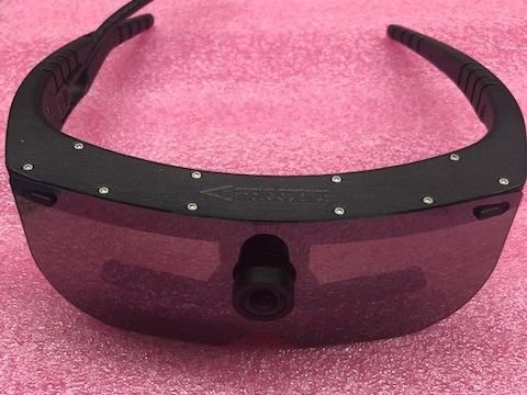
ETVISION MANUAL

the user should consult with Argus prior to proceeding. Argus Science makes no expressed or
implied warranty of any kind with regards to this manual or accompanying documentation.

Argus Science makes no representation, condition or warranty to the user or any other party with
respect to the adequacy of this manual or accompanying documents for any particular purpose or
with respect to its adequacy to produce a particular result. The ETVision system is intended for
use in research conditions and Argus Science makes no declaration of suitability for safety
critical uses, including, but not limited to, clinical diagnoses, heavy machine operation or other
safety dependent activities.

                                                6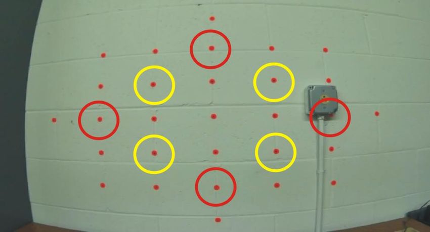
ETVISION MANUAL

3 System Components

                              ETVision headgear-- including eye cameras, scene camera, optional visor, and “
                              type-A-to-micro” HDMI cable.

                              ETVision Controller

                              ETVision PC

                              CAT 5 cable (for connecting ETV PC and Controller).

                              DC power supply for recharging (or directly powering) the Controller.

                              Micro SD card and adapter for use in Controller and ETVision PC.

3.1 ETVision Wearable Optics
The wearable optics unit resembles an eyeglasses frame that can be worn by itself or over the
participant’s prescription eyeglasses. It contains miniature “eye cameras” that view each eye and a
“scene camera” that views the scene in front of the participant, and a microphone. An optional visor
can be mounted to front of the headgear.

The left and right bottom sections of the frame each include a panel containing a camera and a pair of
LEDs. The panels rotate within an outer enclosure so that it is possible to adjust the camera vertical
aiming direction with respect to the optics frame. Although these panels are usually best left in their

                                                    7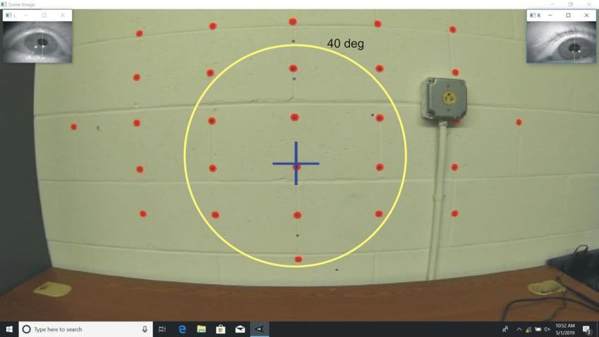
ETVISION MANUAL

standard position, it may be necessary to use this adjustment if facial structure makes the optics frames
sit in an unusual position or angle on the face. See Appendix H (section 9.8) for details.

The frame comes with three nosepieces that can be interchanged to adjust the vertical position of the
entire frame with respect to the face. To remove a nosepiece, simply pull the nosepiece horizontally
away from frame. Attach a nosepiece by pressing the two pins on the nosepiece into the mating holes
in the frame. The frame can also be worn with no nosepiece to position the frame at the lowest
possible position on the face.

A microphone is located in the part of the frame that sits just above the participant’s eyebrows.

An optional sunshield (“visor”) attaches and detaches from the frame by mating small slots at the
upper corners of the visor with small hooks on the frame. See Appendix J (section 9.10) for mounting
instructions.

The scene camera lens protrudes from the frame
                                                                                               Lens focus
just above the nosepiece. Scene camera focus is                                                adjustment
adjusted by rotating the lens. An M2, hex head,                                                 setscrew
nylon tip setscrew, located at the bottom of the
lens assembly, controls the “tightness” of the focus
adjustment, and should be tight enough to prevent
unintentional rotation of the lens.

An HDMI type cable extends from the right
temple clamp (piece that extends from the temple
to the top of the ear). It connects to the frame with
a micro HDMI connector in the temple clamp, but
is intended to be disconnected only if it necessary to replace the cable. Normally the cable should
remain connected to the frame. The other end of the cable has a standard type A HDMI connector and
connects to the ETVision Controller. The cable is a standard “type-A-to-micro” HDMI cable and
instructions for removing and replacing the cable are in Appendix F (section9.6).
                                                    8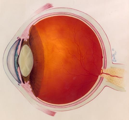
ETVISION MANUAL

3.2 ETVision Controller
The ETVision Controller connects to the ETVision Wearable Optics with the HDMI cable extending
from the wearable optics frame. Besides the type A HDMI port, the Controller has a micro SD card
slot, a phono jack, a LAN port, a power supply connector, a power button and power LED, and a
record button and record LED. Both LEDs have multiple colors to indicate various possible states as
described in Appendix A (section9.1) of this manual.

The HDMI port accepts the type A HDMI connector from the ETVision Optics cable. A set screw on
the bottom of the Controller, directly under the HDMI port is used to secure the HDMI cable
connector after insertion.

The Controller can be connected to the ETVision Laptop using the LAN port and standard LAN cable,
or via Wifi. Alternately, the Controller can record video and audio data directly to a micro SD card.

If the Controller is connected to the ETVison Laptop, either with a LAN cable or Wifi, audio from the
microphone on the optics frame is transmitted to the application on the Laptop, and audio from the
Laptop microphone is transmitted to the phono jack on the Controller. If headphones or earbuds are
connected to the Controller phono jack and worn by the participant, this enables two way
communication with someone near the laptop.

                                                 9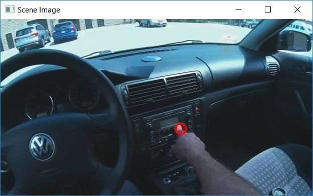
ETVISION MANUAL

An adjustable belt, supplied with system, threads through two removable “loops” on the Controller
Case and can be used hold the Controller on the participant's waist. The Controller “loops” are each
attached to the case with two screws. The screws can be loosened to remove or install the belt.

The Controller contains a Lithium Polymer battery. The battery charges whenever the provided DC
power supply is connected to the Controller power connector and plugged into an AC socket. The
power unit supplied with the system is equipped with the appropriate AC adapter for the AC power
specifications of the intended destination country. The system can be run using the DC power supply
even when the battery is fully discharged, however the battery will charge most rapidly when the
system is idle. When fully charged the battery will power the system for about 5 hours when all
system features are being used. The battery will recharge in about 4.5 hours when the system is idle.

3.3 ETVision PC
ETVision systems usually include a laptop PC running Windows 10 (“ETV PC”). When supplied by
Argus Science, as part of the ETVision system, the ETVison software application is pre-installed by
Argus Science. If the ETVision PC (“ETV PC”) is not supplied by Argus Science see Appendix E
(section 9.5) for required PC specifications and software installation instructions.

The ETV PC laptop includes WiFi capability, a LAN port, USB ports, and an SD card slot. The
ETVision system uses micro SD cards. Micro SD cards must be placed in a micro-to-standard SD
card adapter before inserting in the SD card slot on the ETV PC.

If the ETVision PC was supplied by Argus Science as part of the ETVision system, the PC should
automatically connect to the controller via the LAN port if a cable is connected or via WiFi if a cable
is not connected. If the ETVision PC was not supplied with the system, or if ETVision software is
being updated from a version prior to v.1.0.3.4, see Appendix E for software installation instructions.

                                                  10
ETVISION MANUAL
4 Interconnections
Basic ETVision System Interconnections
(headphones not normally supplied as part of ETV system)
11ETVISION MANUAL
ETVision connection to External Device – Method 1
(All other connection are as shown in the “Basic System Interconnections” diagram)
12ETVISION MANUAL
ETVision connection to External Device – Method 2
(All other connection are as shown in the “Basic System Interconnections” diagram)
13ETVISION MANUAL
ETVision connection to External Device – Method 3
(All other connection are as shown in the “Basic System Interconnections” diagram)
14ETVISION MANUAL
If the ETVision PC was supplied by Argus Science as part of the system, ETVision will be set to
always “load as administrator”. If a cable connection between the Controller and the PC is detected,
the system will automatically connect via the cable. If a cable connection is not detected, the system
will automatically connect via WiFi. If the ETVision PC was not supplied with the system, or if the
ETVision app is reset to not have administrator privileges, see Appendix E (section 9.5) for LAN setup
instructions.
To connect ETVision to an external device using “Method 3” (last diagram, above), click the WiFi
Network Icon in the Window 10 “system tray” (near bottom right of screen) to bring up a list of
possible WiFi connections, and select an available WiFi access point. To once again use WiFi to
connect the ETVision controller and PC, it will be necessary to close this connection. When
connection to the access point is closed, the connection should automatically revert to “ETVnnnn”
where nnnn is ETVision Controller serial number. If it does not, see section 9.5.2 for instructions to
manually re-establish this connection.
15ETVISION MANUAL
5 Abbreviated Instructions
Be sure controller battery is charged, that controller is connected to optics
unit, and that controller is communicating with ETVision PC (see sections 7.1-7.3).
Position wearable optics unit on participant (see section 7.4).
o Select proper nosepiece (or no nosepiece) to insure that eye images are in correct
position near vertical center of camera image
o If nosepiece selection is not sufficient to position both eyes properly, use the eye
camera tilt adjustment on one or both eyes to insure that both eye images are in
acceptable positions (section 9.8).
Calibrate participant (see section 7.5)
o Do Auto Calibration (section 7.5.1).
Click Auto Calibration icon .
Have the subject fixate the black dot at the center of an Auto Cal target
display.
When the auto cal target displayed on the ETV PC screen disappears, auto cal
is complete. If sufficient accuracy is observed, proceed to data collection.
o If auto cal target cannot be automatically recognized due to lighting conditions, or if
more calibration points are needed for additional accuracy, do manual single or
multiple point calibration .
Manual single point calibration (section 7.5.2)
Click manual calibration icon .
have participant fixate point near horizontal center and just below
vertical center of scene camera image
Left click the point on the scene camera image.
If needed, add another 4 points
Have participant fixate points to upper left, upper right, lower left and
lower right of center point, and click on each as it is fixated. (see
section 7.5.3 for suggested position of 4 “corner” points).
Click active calibration icon to close calibration mode.
Record gaze data directly on ETVision PC (see section 7.7.1).
Or record eye and scene video to an SD card on the controller (see section 7.7.2).
16ETVISION MANUAL
6 Eye Tracking Basics
To understand how eye tracking works, it is important to have a basic knowledge about the structure
of the eye.
The pupil is an aperture, or opening,
in the iris that allows light to enter Sclera Retina
into the eye. Unless viewed exactly
on-axis with a light source, the pupil
Iris
appears black.
The iris, which is the colored part of
Pupil
the eye, opens and closes to control
the pupil size.
On its way to the pupil, light passes Cornea
through the cornea, which is a thin,
film-like tissue that covers the eye. Lens
The cornea is mostly transparent;
however, some light is also reflected
from the cornea.
The sclera is the white part of the eye.
ETVision uses a technique of eye tracking
known as “Pupil to CR” Tracking. This
method uses the relationship between two eye
features, the black pupil and mirror
reflections from the front surface of the
cornea (Corneal Reflections, or CRs), to
compute gaze within a scene.
Light from a pair of harmless near infra-red
LEDs on the head gear illuminate the eye
area. The near IR light is almost invisible to
the user, so it does not cause a distraction,
however it is visible to the eye camera. The
mirror reflections of these light sources from the front surface of the cornea (CRs) appear in the
camera image as a pair of bright dots.
When the eye rotates in its socket, the center of the pupil moves relative to the spots. By comparing
the relative position of the pupil and the CRs, the eye tracking system can compute the pointing
direction of the eye visual axis relative to a coordinate frame centered at the scene camera. During
periods when the headgear remains stationary on the head, eye gaze direction can also be computed
from pupil or CR position alone, and this can allow the system to continue to compute gaze when only
a subset of the eye image features can be successfully identified.
17ETVISION MANUAL
By computing the point at which the lines of gaze from the two eyes converge, the gaze point can
represented as spot on the scene camera image.
Since the geometry of the eye structures and the position of the optics with respect to the face vary
somewhat from person to person, gaze computation accuracy can be improved by incorporating data
from calibration points (points at which the person wearing the optics is known to be fixating a
particular point on the scene camera image). Excellent accuracy is often achieved with a single
calibration point, but can sometimes be improved with additional points.
18ETVISION MANUAL
7 Basic System Operation
7.1 Charge Controller battery
To be sure that the Controller battery will have maximum use time fully charge the battery as follows.
Connect the Controller power supply to the Controller and to the AC power source.
If the power LED is off the battery is already charged. Disconnect the power supply, and
proceed to the next section.
If the power LED is white, the battery is charging. When fully charged the LED will turn off.
(This may take up to 4.5 hours if the battery was fully discharged). Disconnect the power
supply, and proceed to the next section.
If the power LED is green or yellow when the power supply is connected this means that the
system has been booted up (it is not in its idle state) and will not charge at the fastest rate.
Press and hold the power button for 5 seconds and then release it to put the system in the
“idle” state. The LED should turn off if the battery is already fully charged or white if the
battery is charging. When fully charged the LED will turn off. (This may take up to 4.5 hours
if the battery was fully discharged). Disconnect the power supply, and proceed to the next
section.
When the Controller is communicating with the ETVision laptop application (see section 7.3) the
battery charge percentage is displayed. Note that even if the battery is fully discharged, the system
can be operated, and including all system functions, with the power supply connected to the Controller
and plugged into AC power. The battery will charge in this case, but charging may take substantially
longer than when the Controller is in the idle state.
7.2 Connect Controller to Wearable Optics Unit
Connect the cable extending from the optics unit temple clamp (ear piece) to the Controller HDMI
port. After inserting the HDMI connector, use the setscrew on the Controller bottom panel, just below
the HDMI connector, to secure the connector. Note that it is not necessary to “tighten” this set screw.
Turn the setscrew just far enough for it to make contact with the connector and create enough friction
to keep the connector in place. Remember to loosen the setscrew before trying to disconnect the
HDMI cable from the Controller.
19ETVISION MANUAL
7.3 Establish communication between Controller and
ETVision application
If a LAN (CAT 5) cable is connected between the ETV PC and the ETV Controller, the system will
communicate via the LAN cable. This is the most stable type of connection, but the participant is
“tethered” to the laptop. If a LAN cable is not connected between these components, the ETV PC and
Controller will communicate via WiFi. In this case the participant will be free to move about so long
as the participant carries the Controller by wearing it on the provided belt or by some other means, and
does not move beyond WiFi range from the PC.
7.3.1 Boot up Controller
Assuming the power supply is not connected to the Controller (battery only), the power LED will be
off if the Controller is not yet booted up. Press the power button and release after 1 sec. The power
LED should turn blue to indicate that the battery has at least a 15% charge and the system is booting.
The boot process will take about 1 minute. The LED will remain blue after boot up is complete.
If the power LED turns red, this means that the battery has less than 15% charge. Either return the
unit to idle and charge the battery as described in section 7.1, or plug in the power supply (LED will
turn yellow) and proceed with the power supply connected.
7.3.2 Run the ETVision Application on the ETVision PC
Run the ETVision application either by clicking the ETVision application icon on the Win10 desktop
or selecting “Argus Science->ETVision” from the Windows 10 Start menu. Note that it is also OK to
launch the ETVision application before booting up the Controller (as described in the previous
section). Note: if ETV PC was not supplied by Argus Science as part of the system, see Appendix E
for proper LAN and Wifi setup.
The ETVision application will appear as shown below. A menu shortcut (tool) bar appears at the top,
with two eye image windows just below it, and a scene image window below that.
Subject
Auto-Calibration
Subject System Control Data Display Battery Charge
File Record Calibration Table Window Window Indicator
Eye Image
Windows SD card WiFi
detect Indicator
Scene Image AC Power
Window
detect
20ETVISION MANUAL
If the ETVision Controller has not finished booting, the three video windows (left eye, right eye, and
scene) will be blank. Live video should appear in the video windows as soon as the Controller
finishes its boot sequence. The SD card indicator will appear only if an SD card is detected. The
battery charge indicator will appear if there is either a LAN or WiFi connection to the Control Unit.
The AC power detect indicator will appear only if the AC power supply is connected. The WiFi
indicator will appear only if there is a WiFi connection to the Control Unit. If a LAN (as opposed to
WiFi) connection is detected a LAN icon will appear in place of the WiFi icon.
Clicking the “Settings” icon on the ETVision tool bar will open a System Control Table window.
If running ETVision for the first time after installation, the default settings should be in place and will
be appropriate. These can be checked, if desired, as described in Appendix D (section9.4).
21ETVISION MANUAL
7.4 Position wearable optics unit on participant
If desired, use the provided belt to fasten the ETVision Controller to the participant’s waist.
Alternately, have the participant hold the Controller in some other way, or support the Controller on a
surface near the participant. Assuming indoor use, it is usually not necessary to use the optional
filtered visor, but the visor may be used if desired. (See section 8 for outdoor use).
Have the participant put on the optics frame just as they would a pair of eyeglasses. If the participant
is wearing prescription eyeglasses, the ETVision frame can simply be worn over the glasses as shown
in one of the photos below.
When the subject is wearing the ETVision frame, the top of frame should be just above the eyebrows.
If the person is wearing prescription eyeglasses, the bottom of the ETVision frame should be near the
bottom of the eyeglasses frame. An image of the left and right eye should appear in the Left Eye and
Right Eye windows, on the ETVision application. When the subject is looking more or less straight
ahead, the iris and pupil of each eye should be more or less centered vertically in the window
(although it need not be “precisely” centered). Correct positioning is shown in the photos and screen
shots below. It is important that both eye images be vertically centered (at least approximately)
when the subject is looking straight ahead.
subject not wearing eye glasses subject wearing eye glasses (note specular
reflections near bottom inner corners)
reflections near bottom inner corners)
If the ETVision frame is not positioned correctly on the face, as described above, select a different
nosepiece or remove the nosepiece altogether to position the frame higher or lower on the face as
necessary. It is suggested that the participant completely remove the frame before the nosepiece is
swapped or removed. The photos, below, show examples of positioning that is correct as well as
examples of positioning that is either too high or too low on the face.
22ETVISION MANUAL
Correct optics position Correct optics position on subject with eye glasses
Optics too low (choose a taller nosepiece) Optics too high (choose a shorter nosepiece)
In some cases, facial structure may be such that the optics frames are severely tilted on the face, and
the two eye images appear in radically different vertical positions on the eye camera images. In this
case, choose a nosepiece that properly positions one eye, and use the eye camera panel tilt adjustment
to correct the position of the image on the other eye. Follow instructions in Appendix H (section 9.8)
to adjust the camera panel tilt angle. In even more unusual cases, facial structure may be such that
none of the nosepiece choices correctly position either eye. In this case both eye camera panels can be
adjusted to properly position the eye images.
When the subject is looking more or less straight ahead both the eye pupils, and the corneal reflections
(mirror images of the two LEDs that are directed towards each eye) should be visible as shown in the
screenshot on the next page. System recognition of the pupil is shown by a red ellipse superimposed
on the pupil boundary and a large green cross indicating the pupil center. Recognition of the corneal
reflections (CRs) is shown by smaller blue crosses indicating their centers.
The yellow crosses show detection of the upper and lower eyelid boundaries just above and below the
pupil center. Note that the upper and lower boundaries of the iris are often obscured by the eyelids.
If the upper or lower boundary of the iris is visible, that boundary, rather than the eye lid boundary,
might sometimes be indicated by the yellow bar. The vertical position of the upper and lower eyelid
boundary markers (yellow crosses) are available as data items for recorded data files as well as
streaming data, but are not default items and must be selected on the Data Selection dialog (see
section 7.7.1.1).
23ETVISION MANUAL
When the participant looks above the center of the scene camera field of view, or to extreme
horizontal angles, one of both corneal reflections may reach the edge of the cornea or be obscured by
an eyelid and become undetectable or unreliable. The pupil, however should usually remain visible
and be stably detected by the system until eye angles become quite extreme. Of course, both the pupil
and corneal reflections will be obscured during eye blinks.
The Scene window shows the image from the head mounted scene camera with a blue cross indicating
the participant’s point-of-gaze (POG). If both pupil images are being recognized, this cursor will
probably be present, but may not be a very accurate representation of POG until subject calibration is
performed, as described in the next section.
24ETVISION MANUAL
7.5 Calibrate participant
This section is a simple description of the recommended calibration procedure. A more complete
description of the calibration function capabilities and options is presented in Appendix B (section
9.2).
The simplest and quickest procedure is the Auto Calibration described in section 7.5.1. It is suggested
that this be used first and that manual procedures described in sections 7.5.2 and 7.5.3 be used only if
Auto Cal results are not satisfactory.
7.5.1 Auto Calibration
Once Auto-Calibration is activated, the participant simply has to fixate the black dot at the center of a
red and blue target pattern. The system will recognize both the target and steady gaze near the target
and will automatically complete a single point calibration.
The target pattern is displayed on the ETV PC screen when Auto-Calibration is activated, and is also
provided as a bit map image file that can be printed as well as one that can be displayed on a cell
phone screen. (Consult Argus Science for link to download the Auto-Calibration Target image files).
25ETVISION MANUAL
First, be sure the wearable optics are properly positioned as described in section 7.4.
To use the Auto-Calibration feature proceed as follows:
1. Click the “Subject Auto-Calibration” icon on menu bar. The Icon will change from gray scale
to a color image to show that Auto Cal is active, and an Auto-Calibration target will appear in the
data display window, to the right of the scene image window.
2. Have the subject hold their head so that a target display (either on the ETV PC screen, a paper
printout, or a cell phone screen image) is about arms length from their face and near the center of the
ETV scene image, and ask them to fixate the black dot at the center of the target image.
3. The ETV system will indicate recognition of the target by placing a small yellow cross over the
target image on the scene image window. When the system detects that gaze is near the target and
steady, calibration data will be automatically entered, the target displayed on the ETV PC screen will
disappear, and the Auto-Calibration icon will return to a gray scale image.
4. Check calibration accuracy by asking the subject to look at some landmarks or targets visible in the
scene image and observing the accuracy of the point-of-gaze cursor.
In most cases, a single point calibration using the Auto-Calibration Target as described above will
provide sufficient accuracy over the visual field of interest. If Auto-Calibration results are
satisfactory, proceed to section 7.6.
As described above, system recognition of the Auto-Calibration target is indicated by a yellow cross,
superimposed on the center of the target image on the Scene Image window. If lighting conditions or
other factors make it difficult for the ETV system to recognize the Auto-Calibration target (yellow
cross does not appear on target center), a manual single point calibration can be done as described in
section 7.5.2. If accuracy over the required visual field is not satisfactory after Auto-Cal, or after a
single point manual calibration, the manual calibration procedure described in section 7.5.3 allows
additional calibration points to added.
26ETVISION MANUAL
7.5.2 Single Point Manual Calibration
If the Auto-Calibration described in the previous section produces satisfactory results, proceed
to section 7.6. Otherwise proceed as described below.
Sections 7.5.2 and 7.5.3 describe the recommended procedure for manual single and multiple point
calibrations. A more complete description of the calibration function capabilities and options is
presented in Appendix B (section 9.2).
To be sure that ETVision is set for the default manual calibration procedure described in this section,
click the “Settings” icon if necessary to bring up the System Control Table window and select the
“Subject Calibration” tab. Be sure “Calibration Type” is set to "Click on Scene Image Points”, and
“Total Calibration Points” is set to 9. Note that this does not mean that nine calibration points must
be used, but rather that the maximum number of points is 9.
Click the Calibrate icon on the ETVision tool bar. The Calibrate icon will turn red to indicate
calibration in progress. At this point the blue POG cursor on the Scene window will probably begin to
move in the same pattern as the participant’s gaze, but will often be significantly displaced from actual
gaze points. A yellow cross will show the position of the first point used in the previous calibration,
and gray crosses will show other points used in the last calibration. This is for information only. The
same positions do not need to be used for the current calibration.
1. Have the participant hold their head still and look at a point near horizontal center and
at or just below the vertical center of the scene camera image (somewhere within the
yellow circle on the scene camera image below). This can be done by asking the person to
fixate an existing visual target in the environment or by asking the person to fixate the tip of a
pointer (or laser pointer spot) being positioned by the equipment operator or an assistant.
Theoretically the target can be at any distance from the participant, but it is usually most
convenient to use visual targets that are 2 or 3 feet (1/2 to 1 meter) away.
Yellow circle shows approximate area on the scene image within which a target point
should usually be located for single point calibration.
27ETVISION MANUAL
If the person is asked to fixate an existing visual target in the environment it may be necessary
to have them rotate their head a bit either up or down, or side to side, so that the target point
appears near or slightly below the center of the scene camera image. If the participant is asked
to look at the tip of a pointer, it is usually easiest if the person holding the pointer can also see
the ETV PC screen so that they can hold the pointer tip at the right place.
When the subject looks at the requested central visual target the Left Eye and Right Eye
windows should indicate that the system is recognizing the pupil and the corneal reflections
for both eyes.
2. In the Scene window, left click on the target that the participant is attempting to fixate.
A small green cross will appear at that point in the Scene window, and the blue POG cursor
should jump right to that visual target and remain there until the subject looks away from the
target. If the blue cursor jumps to some different position (for example, if the subject blinks or
looks away from the point just as the mouse is clicked) right click on the same spot to "undo"
the data entry, and repeat steps 1 and 2.
3. Check for satisfactory performance over the desired visual field region. Have the subject
look at visual targets at several points within the scene image area that will important for the
experiment or task and notice whether the blue point-of-gaze cursor correctly indicates the
points being fixated.
4. If performance is suitable for the task at hand click the "Calibrate" icon to close the
calibration procedure ("Calibrate" icon will revert to black), and proceed to section 7.6.
Otherwise, add calibration points to improve accuracy as described in the next section.
7.5.3 Adding Calibration Points if Needed
A single point calibration as described in the preceding section will often result in better than 1 degree
accuracy over the central 40 degree diameter field of view, and sometimes beyond that range. The
yellow outline shows approximately the central 40 degree diameter field of view.
28ETVISION MANUAL
If the point-of-gaze measurement error tends to grow significantly as the subject looks away from the
central point, accuracy can usually be improved by adding calibration points.
Not all tasks require that gaze point be known with maximum accuracy, and sometimes very rapid
calibration may be more important than best possible accuracy. If measurement accuracy is judged to
be suitable for the task at hand, the user may elect to close the calibration procedure (click the
“Calibrate” icon so that it reverts to black) and proceed with data collection, etc.
If, after the single point calibration, accuracy needs to be improved, it is suggested that at least an
additional 4 calibration points be added in approximately the positions indicated by the yellow circles
superimposed on the Scene window screen shot below. Note that these points are 15 to 20 degrees
visual angle from the center of the scene camera field of view.
Yellow circles show approximate areas on the scene image within which additional 4 target points
should usually be located.
1. Do not close the calibration procedure after the single point calibration described in the
previous section (Calibrate icon should remain red).
2. Ask the participant to continue holding their head fairly still and look at a visual target at one
of the 4 positions shown in the screen shot. As with the single point calibration, it can be an
existing target in the visual environment or the tip of a pointer device, etc. Also as with the
single point calibration, the subject can be asked to rotate their head slightly to ensure that
visual targets appear at the appropriate positions in the scene camera image.
3. Left click on the point in the Scene window. A small green cross will appear at that point in
the Scene window, and the blue POG cursor will usually move slightly closer to the true point
of gaze. As with the single point calibration if the blue POG cursor jumps to a point
29ETVISION MANUAL
significantly farther away (probably because the subject blinked or looked away just as the
data was entered) right click to “undo” the data entry and repeat steps 2 and 3.
4. Repeat steps 2 and 3 for the other three points. Note that the eye pupils must be recognized
for all of the points. The corneal reflections should be recognized on the bottom 2 calibration
target points, but often may not be recognized on the top two points, and this is OK.
5. Check for satisfactory performance over the desired visual field region as previously
described. If satisfactory, click the ”Calibrate” icon to close the calibration procedure
(“Calibrate” icon turns black) and proceed to the next section.
The procedure described above should almost always result in good measurement accuracy with
in the visual field enclosed by the boundary connecting the outer 4 calibration points. Accuracy
will often be quite good significantly beyond this range, but error may sometimes increase
significantly as the subject looks progressively farther away from this region. In this case,
accuracy can usually be improved, before closing the calibration procedure, by adding an
additional 4 points approximately in the areas shown by the red circles, below. Simply repeat the
procedure described above for these points before clicking the Calibrate icon to close the
calibration procedure.
Red circles show suggested areas for calibration target points 6-9.
With default settings, the maximum number of calibration points is 9. (This maximum value can
be changed as described in Appendix B). Additional left clicks on the Scene window, beyond 9
points, will result in the point closest to the click being replaced by the new click. Once the
Calibrate procedure is closed (black “Calibrate” icon), the current calibration cannot be modified.
If the calibration process is re-opened, by clicking the “Calibrate” icon, the current calibration
result is deleted and the process begins again “from scratch”.
30ETVISION MANUAL
After each calibration point is entered (left mouse click), a “confidence” value for that point
appears in the scene window title bar. Proper interpretation of the “confidence” value is discussed
in Appendix B.
The current and previous sections describe the most common (and recommended) use of the
calibration procedure. The system actually allows far more flexible use of the calibration function
and a more complete description is in Appendix B.
7.6 Monitor gaze data and system status
As long as the ETVision laptop is connected to the ETVision Controller with a LAN cable, or remains
within WiFi range (approximately 150 ft in absence of interference), point of gaze and eye image
feature recognition, as well as battery charge and data recording status can be monitored in real time
on the ETVision application. Gaze data is monitored by observing indicators superimposed on the Left
Eye, Right Eye, and Scene Image windows, and if desired by a plot shown on a Data Display window.
7.6.1 Status Indicators
Battery charge is indicated by a battery icon towards the right side of the ETVision tool bar. “Hover”
the mouse over the battery icon to see a battery charge percentage value. The charge values are
displayed to the nearest 5%. Similarly, an SD card icon indicates that an SD card is detected, and
when the mouse hovers over this icon, the percentage used is displayed. A symbol at the far right of
the tool bar indicates whether there is a WiFi or LAN connection to the Controller. Hovering
the mouse over either of these symbols will show the Controller firmware version
7.6.2 Left Eye and Right Eye windows
The images from the left and right eye cameras are displayed in real time on the Left Eye and Right
Eye windows. These windows are opened by default but can be closed, re-opened, or embedded in
the scene image by clicking the “Eye” icon on the menu bar. The Eye icon has 3 different forms and
is really a 3 way toggle switch. The standard view icon indicates that the two eye widows are
opened, as in the screen shot below.
31ETVISION MANUAL
Clicking the standard view icon will change its form to the
“embedded view” icon . In embedded view, the two
eye images, rather than appearing in their own windows,
are embedded at the corners of the scene image, as shown
to the right. When in embedded view, the eye images are
part of the scene video image and scene video recordings
will contain the embedded eye images
Clicking the embedded view eye icon will cause it to
change to an “eye image closed” icon . In this case
the eye images will not be shown at all. Clicking the eye
image closed icon returns to the standard eye image
windows view.
In embedded mode, the
relative transparency of the
scene and eye images can also
be adjusted. Click the “System
Control Table” icon to
bring up the System control
Table dialog, and select the
“Video Source” tab. The
slider labeled “Transparent”
controls the transparency of
the scene image. When the
slider is all the way to the right
(100%) the scene image will be completely transparent and will not cover the eye images at all. When
the slider is all the way left (0%) the scene image will be completely opaque and the eye images will
not be visible. At positions in between the scene image will be partially visible over the eye images.
Whether eye images are shown in standard windows view or embedded view, pupil recognition is
indicated by a red ellipse outline to show the detected pupil outline and a large green cross to indicate
the center of the ellipse. Yellow crosses show detection of the upper and lower eyelid boundaries just
above and below the pupil center. If pupil is not being properly recognized, the red ellipse outline will
unstable or will form around the incorrect feature, and the green cross will not be in a stable position
over the pupil center. The yellow eyelid boundary crosses may sometimes indicate the upper or lower
iris boundary, if this is visible, rather than the eyelid. These feedback indicators can disabled for the
real time eye window displays by unchecking the “Draw Pupil / CR/ Eyelid” check box, on the
System Control Table “Video Source" tab; and can be disabled for recorded eye video files by
unchecking the "Record Pupil / CR/ Eyelid" check box.
If in standard Windows view, either eye window can be moved by dragging the title bar, can be
resized by dragging a corner of the window, or can be set to “full screen” by clicking the “maximize”
symbol on the Eye window title bar. When “maximized” the selected Eye window will show as full
screen, with the other eye window in one top corner and the Scene image window in the opposite
bottom corner. Clicking anywhere within the full screen Eye window will cause it to cover the
32ETVISION MANUAL
alternate eye image and the scene image window displays. Click the “restore” icon to return the
window to normal size.
Although the eye video data is actually updating 180 times per second (and point-of-gaze is computed
and recorded 180 times per second), the Left Eye and Right Eye video displays on the laptop update at
30 Hz.
7.6.3 Scene Image window
The image from the head mounted scene camera is displayed in real time on the Scene Image window.
Point-of-gaze, computed using binocular eye image data, is displayed as blue cross, superimposed on
the image. This window is opened by default but can be closed and re-opened by clicking the “Scene”
icon on the menu bar. After calibration the point-of-gaze (POG) cursor, superimposed on the
scene video image, should accurately show the subjects instantaneous point-of-gaze so long as the eye
pupils are correctly detected. (For some subjects, the pupil may not be detectable or pupil detection
may not be stable when they look at extreme positions near the edges or corners of the scene image
field.) The POG cursor can be either a cross or a circle with user adjustable size, line weight, color,
and transparency. An adjustable smoothing filter is also applied to the POG cursor. Controls for POG
cursor appearance and adjustable smoothing filter are accessed from the System Control Table
window, “System Configuration” tab, “Advanced Configuration” dialog (see section 9.4.4.5 in
Appendix D).
In the screen shot, above, the POG cursor is the red circle near screen center
The Scene Image window can be moved by dragging the title bar, can be resized by dragging a corner,
or can be set to “full screen” by clicking the “maximize” symbol on the Scene Image window title bar.
Click the “restore” icon to return the window to normal size.
33You can also read