EU/US 260G Assembly, Operation & - (Reference) Parts Manual - Pulse Fitness

Page created by Lois Garcia
 
CONTINUE READING
EU/US 260G Assembly, Operation & - (Reference) Parts Manual - Pulse Fitness
260G Assembly, Operation &
        (Reference) Parts Manual

                          EU/US
Company Addresses

Global Corporate Headquarters                                      Regional (Distributor/Dealer) Address(es)

Address:                                                           Current List of Distributors/Dealers:
Pulse Fitness Ltd., Radnor Park, Greenfield Road, Congleton,       https://www.thepulsegroup.co.uk/pulse-global
Cheshire, CW12 4TW, England, United Kingdom

Sales/Marketing:                                                   Americas
Tel: +44 (0)1260 294600                                            North America
Fax: +44 (0)1260 299282
Email: info@pulsefitness.com                                       Fitness Equipment Depot Worldwide

Service:                                                           Address
Tel: +44 (0)1260 294600                                            45 Grand Blvd, Brentwood, NY, 11717
Email: global.service@pulsefitness.com
                                                                   Sales/Marketing
Corporate Website:                                                 Tel: +1-631-656-8826 ext 104
www.pulsefitness.com                                               Toll Free - Tel: +1-866-965-4653
                                                                   Fax: +1-631-656-8853

                                                                   Service
                                                                   Tel: +1-631-656-8826 ext 106

                                                                   Distributor/Dealer Website:
                                                                   www.fitnessplus.com

                    Assembly, Operation & Parts Manual         G-Range               CV                  Pg02
Overview

  Before using this product, it is essential to read ALL of this manual and the documents it references prior to, choosing a
  location, assembling or operating this piece of equipment. This manual describes the equipment's setup its installation and
  instructs how to use it correctly and safely. It is of the utmost importance that any User of the PULSE FITNESS Run (Low
  Impact 'Elevation' Treadmill) is fully trained in its operation! Please ensure that the instructions given in General Safety
  Precautions section are understood by ALL Users. Keep this manual for future reference.

  WARNING: Health-related injuries may result from incorrect or excessive use of exercise equipment. PULSE FITNESS STRONGLY
  recommends gaining professional medical advice before using fitness equipment, particularly if the user has a family history of high
  blood pressure or heart disease, is over the age of 45, smokes, has high cholesterol, is obese, or has not exercised regularly in the
  past year.

  Always warm up by exercising gently before progressing to a full programme of strenuous exercise. Similarly, reduce the level of
  activity gradually towards the end of the exercise programme.
  Heart rate monitoring systems may be inaccurate.
  Over exercise may result in serious injury or death. If you feel faint, light-headed, dizzy or suffer from any kind of pain or exhaustion,
  STOP exercising immediately.
  NOT suitable for Medical/Therapeutic purposes.

  Ensure equipment is checked regularly for signs of damage and wear. Do not use equipment if faulty or damaged, repair using only
  genuine PULSE FITNESS parts fitted by an authorised person.

  SERIOUS INJURY MAY OCCUR IF THESE PROCEDURES ARE NOT FOLLOWED.

            Assembly, Operation & Parts Manual                 G-Range                  CV                     Pg 03
Overview (Continued)

   Statement of Purpose:
   The treadmill is an exercise machine that enables users to walk or run, in place, on a moving surface.

   FCC Warning - Possible Radio / Television Interference.

   NOTE: This equipment has been tested and found to comply with the limits for a Class A digital device, pursuant to part 15 of the FCC
   rules. These limits are designed to provide reasonable protection against harmful interference when the equipment is operated in a
   commercial environment. This equipment generates, uses and can radiate radio frequency energy, and if not installed and used in
   accordance with the instruction manual, may cause harmful interference to radio communications. Operation of this equipment in a
   residential area is likely to cause harmful interference, in which case the user will be required to correct the interference at his own
   expense.

   Class SA (Studio): Professional and / or commercial use.

   CAUTION: Any changes or modifications to this equipment could void the product warranty.
   Any service, other than cleaning or user maintenance, must be performed by an authorised service representative. There are no user
   serviceable parts.

             Assembly, Operation & Parts Manual               G-Range                  CV                    Pg04
Table of Contents

1   260G Overview                                  07         7    Connections to Power Supply                       21
                                                                     7.1 Wiring the Motor                            21
2   Contents of 260G Flat Pack                     08
                                                              8    Important Safety Instructions                     22
                                                                     8.1      Introduction                           22
3   Assembly                                       09                8.2      Set-Up                                 25
      3.1   Connecting the Support Columns         09                8.3      Operation                              25
      3.2   Attaching the Column End Caps          10                8.4      Electrical Power Requirements          26
      3.3   Attaching the Top Assembly             11                8.5      How to Position and Stabilise          26
      3.4   Attaching the Neck                     12                8.6      Safety Clearances                      27
      3.5   Attaching the Dashboard Valance        13                8.7      Power Switch                           28
      3.6   Fitting the Storage Buckets            14                8.8      Install Coaxial & Ethernet Cables      28
      3.7   Fixing the Motor Cover                 15                8.9      Power Cord Routing                     28

4    Installing Console                            16
                                                              9    General Safety Precautions
                                                                     9.1      Grounding Instructions
                                                                                                                     29
                                                                                                                     29
      4.1   Attaching / Re-Attaching the Console   16                9.2      Emergency Stop                         30
      4.2   Wiring / Re-Wiring the Console         17                9.3      Emergency Stop Safety Clip             31
      4.3   Using the Console                      18                9.4      Using the Emergency Stop Safety Clip   32
      4.4   Securing the Book Holder               18                9.5      Speed Confirm. Quick Controls (C5.0)   33
                                                                     9.6      Speed Confirm. Quick Controls (C6.0)   34
5   Fully Assembled 260G Run                       19                9.7      Emergency Dismount                     35

6   Quick Control Panel                            20         10   Installation
                                                                     10.1 Location
                                                                                                                     36
                                                                                                                     36
      6.1 260G ‘Quick’ Control Panel               20
                                                                     10.2 Feet Adjustment                            37
                                                                     10.3 On / Off Switch                            38

              Assembly, Operation & Parts Manual        G-Range            CV                   Pg 05
Table of Contents (Continued)

11   Adjust and Tension the Running Belt            39
      11.1    Running Belt Alignment                39
      11.2    Tracking (Centring) a Running Belt    40
      11.3    Tensioning an Existing Running Belt   41

12   Cleaning & Maintenance
      12.1    Preventive Maintenance Tips
                                                    42
                                                    42
      12.2    Cleaning the Equipment                42
      12.3    Compatible Cleaners                   43
      12.4    Preventive Maintenance Schedule       43
      12.5    How to Obtain Product service         44

13   Specifications                                 45
      13.1    Specifications                        45
      13.2    Physical Dimensions (L x H x W)       47
      13.3    Weight (kg/lbs)                       47
      13.4    Console                               47

14   Parts Lists & Exploded Diagrams                50
      14.1    Parts Lists & Exploded Diagrams       50

15   User Notes                                     51

             Assembly, Operation & Parts Manual          G-Range   CV    06
                                                                        Pg
1   260G Overview

                                                             260G Run
A
                                                    G   A Console (Series 1, 2 or 3)

B                                                   H   B ‘Quick’ Controls

C                                                   I   C Emergency Stop

                                                    J   D Handpulse Resistors

                                                    K   E Treadplates
D
                                                        F    Running Belt

                                                    L   G Book Rest

                                                        H iPod® / iPhone® Dock

                                                         I   Drinks Bottle

                                                        J    Storage Bucket
E                                                       K Handrails
                                                    M
                                                        L    Front Upright Supports

                                                        M Transportation Wheels
F
                                                    N   N Roller End Cap

     Assembly, Operation & Parts Manual   G-Range       CV                    Pg 07
2   Contents of the 260G Pack
                               E
                                                                         The 260G Run will have to be assembled from
                                                                         the flat pack. The contents of the pack are as
                                                                I        follows:
                                              G
                                                                    A    Main Body
                                                                    B    Top Assembly
                                                          F         C    Front Column Endcaps
D                                                                   D    Upright Columns
                                                      D     L       E    Storage Buckets
                                                                    F    Console (Series 1, 2 or 3)
                     J                                              G    Drinks Bottle
                                                                    H    Motor Cover Moulding
                                                            M
                                                                    I    Book Holder
                                                                    J    Dashboard Valance
                                              H                     K    Front Roller Guides
                                                            N       L    Console Bolts
                                                                    M    Motor Cover Moulding Bolts
                                                                    N    Column Bolts [Bottom]
                                                            O       O    Column Bolts [Top]
    C                                                               P    Dashboard Valance Bolts
                                                                    Q    Front Endcap Bolts
                                                            P       R    Console Column/Neck Bolts

                                                  C                      If any parts are missing then please contact
                                                            Q            PULSE FITNESS' Global Service Team
                                                                         +44(0)1260 294600.

                                              K             R

         Assembly, Operation & Parts Manual       G-Range           CV                   Pg 08
3   Assembly of 260G

                                                                  3.1 Connecting the Support Columns

                                                                  Attach the support columns by placing the column
                                                                  against the front brackets and insert the bolts with
                                                                  washers into position whilst making sure you
                                                                  support the column. [See Figure A].

                                                                  Note: Loosely tighten the bolts to, allowing 5mm
                                                                  of adjustment for connecting the top assembly.

                                                                  Tools Required:
                                                                  8mm Allen Key
                                                                  [M10x25 Cap Head Bolt w/Spring Washer x12]

                                 Figure A
                                 Connecting the Support Columns

     Assembly, Operation & Parts Manual        G-Range            CV                   Pg 09
Assembly of the 260G (Continued)

                                                                   3.2 Attaching the Column End Caps

                                                                   Push the end cap into the column and insert the
                                                                   bolt through the hole, tightening with your fingers
                                                                   and then finishing off with an allen key. [See Figure
                                                                   B]. This procedure can be left to the end of the
                                                                   assembly once the side columns have been
                                                                   tightened into position.

                                                                   Tools Required:
                                                                   6mm Allen Key
                                                                   [M8x20 Cap Head Bolt x2]

                          Figure B Attaching the Column End Caps

     Assembly, Operation & Parts Manual       G-Range              CV                    Pg 10
Assembly of the 260G (Continued)

Figure C                                                         3.3 Attaching the Top Assembly
Attaching the Top Assembly                                       Attach the top assembly by dropping it onto the
                                                                 front columns, lifting the handrails and tilting the
                                                                 front brackets down into the front columns. Make
                                                                 sure that the holes are lined up in order to get the
                                                                 bolts into position. Insert the bolts in the correct
                                                                 order
                                                                 1-3 [See Figure C].

                                                                 Note: Once this is in position tighten all bolts
                                                                 securely, including the front column bolts at the
                                                                 base of the treadmill.

                                                                 Tools Required:
                                                                 6mm Allen Key
                                                                 [M8x15 Button Head Bolt x6]

              1

2
                  3

                  Assembly, Operation & Parts Manual   G-Range   CV                    Pg 11
Assembly of the 260G (Continued)
Figure D
                                                               3.4 Attaching the Neck
Attaching the Neck
                                                               Drop the neck through the hole in the dashboard
                                                               moulding and secure with bolts. [See Figure D].

                                                               Tools Required:
                                                               13mm Combination Spanner
                                                               [M8x75 Hexagon Head Bolt x2]

                Assembly, Operation & Parts Manual   G-Range   CV                  Pg   12
Assembly of the 260G (Continued)

Figure E                                                      3.5 Attaching the Dashboard Valance
Attaching the Dashboard Valance
                                                              Slide the dashboard valance into position and
                                                              securely fix [See Figure E].

                                                              Note:
                                                              Be careful not to damage the foam handrails
                                                              during this process.

                                                              Tools Required:
                                                              Phillips Screwdriver
                                                              [M5x20 Pozi Pan Screw x7]

               Assembly, Operation & Parts Manual   G-Range   CV                  Pg 13
Assembly of the 260G (Continued)
Figure F                                                         3.6 Fitting the Storage Buckets
Fixing the Storage Buckets
                                                                 Insert the Storage buckets into the appropriate
                                                                 holes in the dashboard and press down firmly.
                                                                 [See Figure F].

                  Assembly, Operation & Parts Manual   G-Range   CV                   Pg 14
Assembly of the 260G (Continued)
Figure G
                                                                 3.7 Fixing the Motor Cover
Fixing the Motor Cover
                                                                 Carefully slide the motor cover between the two
                                                                 uprights and drop into position [See Figure G].

                                                                 Note:
                                                                 Make sure you do not scratch the front uprights
                                                                 during this process.

                                                                 Tools Required:
                                                                 Phillips Screwdriver

                                                                 Front Screws:
                                                                 No.8x25 Pozi Pan Screw x2
                                                                 Side Screws:
                                                                 M6x25 Pozi Button Head Screw x2

                  Assembly, Operation & Parts Manual   G-Range   CV                      15
                                                                                        Pg
4             Installing Consoles on the 260G
Figure H                                                               4.1 Attaching / Re-Attaching the Console
Attaching / Re-Attaching the Console
                                                                       For details on how to attach Series 1, 2 & 3
                                                                       Consoles, refer to document 135-771-*.

                                                                       NOTE: Fasten Bolts securely.

                                                                       Tools Required:
                                                                       4mm Allen Key

                           NB: Image for illustration only

                  Assembly, Operation & Parts Manual         G-Range   CV                   Pg 16
Installing Consoles on the 260G (Continued)
Figure I                                                               4.2 Wiring / Re-Wiring the Console
Wiring / Re-Wiring the Console
                                                                       For details on how to connect the cables for Series
                                                                       1, 2 & 3 Consoles, refer to document 135-799-*.

                                                                       Carefully pull the Electrical Connectors up from the
                                                                       Column. Ensure that all Electrical Connectors are
                                                                       attached.

                           NB: Image for illustration only

                  Assembly, Operation & Parts Manual         G-Range   CV                   Pg 17
Installing Consoles on the 260G (Continued)
Figure J                                                                4.3 Using the Console
Using the Console
                                                                        For details on how to use each of the Series 1, 2 &
                                                                        3 Consoles, refer to documents:
                                                                          135-1379-* Series 1 (Console 3.5 CV)
                                                                          135-1299-* Series 2 (Console 5.0 CV)
                                                                          135-1300-* Series 3 (Console 6.0 CV) Cirrus V1
                                                                          135-1824-* Series 3 (Console 6.0 CV) Cirrus V2

                                                                        4.4 Securing the Book Holder

                                                                        For Series 1 & 2, carefully line up and firmly push
                                                                        the Book Holder into the console’s allocated slots
                                                                        until it is solidly fixed into position.

                                                                        NOTE: This may take some force. Be careful not to
                                                                        damage the console in the process.

                            NB: Image for illustration only

                    Assembly, Operation & Parts Manual        G-Range   CV                   Pg 18
5   Fully Assembled 260G Run

                                                    Your 260G Treadmill is now ready to use, please
                                                    read the Technical and Console booklets to
                                                    become familiar with all operational and safety
                                                    features before use.

                                                              Caution: MAKE SURE ALL HARDWARE
                                                              IS TIGHT!

     Assembly, Operation & Parts Manual   G-Range   CV                  Pg 19
6              Quick Control Panel
          Figure K
                                                                                                       6.1 260G ‘Quick’ Control Panel
          260G Quick Control Panel

                                                                J                                      The Series 2 & 3 ‘Quick’ Control panel allows
          B                            A                                                  I            the User to adjust the Speed and Elevation in
                                                                                                       larger increments. It is positioned closer to the
                                                                                                       User than the Console for easier access. [See
                                                                                                       Figure K].

                                                                                                       The User needs to press the speed button, then
                                                                                                       confirm the on-screen message when
                              Ascent                                                                   increasing the speed (by pressing the button
                                                                    Speed
        C                                                                                     H        again). To make the speed decrease the button
                                                                                                       only needs to be pressed once.

                                                                                                  A    Ascent increase
                                                                                                  B    Ascent decrease
                                                                                                  C    Low incline
                                                                                                  D    Medium incline
         D                     E                                           F              G       E    Steep incline
                                                                                                  F    Walk (2.0 mph*)
                                                                                                  G    Jog (4.0 mph*)
                                                                                                  H    Run (6.0 mph*)

                                CAUTION                                                           I
                                                                                                  J
                                                                                                       Increase speed
                                                                                                       Decrease speed

Clear instruction needs to be given in order to use these controls. It is the                          * Standard settings setup. These are the
responsibility of the instructor/site to make sure that Users are aware of the function                recommended settings by PULSE FITNESS. It is the
                                                                                                       responsibility of the instructor/site if these speed
of these controls, and are trained in using the equipment before commencing                            settings are changed.
exercise.

SERIOUS INJURY MAY OCCUR IF THESE PROCEDURES ARE NOT FOLLOWED.

                            Assembly, Operation & Parts Manual                 G-Range            CV                       Pg 20
7                                   Connections to Power Supply

    Note :            100-276-* Interface P.C.B.
                                                                                                                                                                                           7.1 Wiring the Motor
                                                                                                                EARTH CABLE FILTER
                                                                                                                Sleeve Colour : N/A
                          Cable supplied w/drive
                                                                                                                                                                  P13 TO FILTER SPADES
                                                                                                                                                                  CABLE                              CAUTION MAINS POWER 120V
                         Cable supplied w/motor                                                                                                                   Sleeve Colour : N/A
                                                                                                                                                                                                     Ensure that the power is turned off and is
                      Cable supplied w/actuator
                                                                                                                                                                  12V PSU                  unplugged at the mains connection point,
                                                                                                                                                                  Sleeve Colour : N/A
                                                                                                                                                                                           BEFORE removing the motor cover and
                                                                                                                                                                  SERIAL CABLE
                                                                                                                                                                                           carrying out any work on the electrical
                                                                                                                                                                  Sleeve Colour : Yellow
                                                                                                                                                                                           components.
                                                                                                                                         Magic Tape X2
                                                                                                                                         as FST X50mm
                                                                                                                                                                 HALL EFFECT
                                                                                                                                                                 SENSOR
                                                                                                                                                                                           Carefully connect the cables as indicated on the
                                            Ferrite                                                                                                              Sleeve Colour :N/A
                                                                                                                                                                                           drawing and check that all the wires are secure and
                                                                                                                                                                                           in the correct ports.
                                                                                                                                                                  12V Power
                                                                                                                                                                  Sleeve Colour :Red

                                                                                                                                                                                                    Make sure that the loom is secured
          Rhymebus
            RM6T-2
                                                                                                                                                          LOOM
                                                                                                                                                                  COAX CABLE
                                                                                                                                                                                                    with a cable tie ensuring the wires have
                                                                                                                                                                  Sleeve Colour :N/A
              Drive                                                                                                                                                                        enough slack to reach the ports without any
                                                                                                                                                                                           tension.
                                                                                                                                                                  NETWORK CABLE
                                                                                                                                                                  Sleeve Colour :N/A
                                                                                                       27

                                                                                                                                                                                           *Refer to document 135-839* for further
                                                                                                                                                                                           instructions.
                                                                                           SWITCH TO                                     EARTH CABLE
                                                                                           TERMINAL BLOCK                                Sleeve Colour :N/A       FILTER CABLE
                                                                                           Sleeve Colour :N/A                                                     Sleeve Colour :N/A

                                                                                                                           SWITCH TO
                                                                                                                           TERMINAL BLOCK
                                                                                                                           Sleeve Colour :N/A
                   MOTOR POWER                         FAN   COMMS
                   CABLE***                                  CABLE
ACTUATOR /         Sleeve Colour :N/A
POTENTIOMETER                                                Sleeve Colour :N/A
CABLE****                       BRAKE RESISTOR
Sleeve Colour :N/A              CABLE**                                    MAIN FILTER
                                Sleeve Colour :N/A                         CABLE
                                                                           Sleeve Colour :N/A

                                                     Assembly, Operation & Parts Manual                                                           G-Range                                  CV                   Pg 21
8         Important Safety Instructions

    8.1 Introduction
    The successful and safe operation of PULSE FITNESS' Run (Low Impact 'Elevation' Treadmill) is dependent upon its proper handling,
    installation, operation and maintenance. The following safety precautions are for safety and guidance. Please read them carefully
    before proceeding to install and/or operate the Treadmill. Specific notices are included in the text where appropriate.

    Read all instructions before using the PULSE FITNESS Run (Low Impact 'Elevation' Treadmill).

    DANGER: To reduce the risk of electrical shock, always unplug PULSE FITNESS products from the electrical outlet immediately after
    using and before cleaning or attempting any maintenance activity. DO NOT remove any cover.

    WARNING: To reduce the risk of burns, fire, electric shock, or injury, it is imperative to connect each product to a properly grounded
    electrical outlet.

    WARNING: Heart rate monitoring systems may be inaccurate. Over exercising may result in serious injury or death. If you feel faint,
    stop exercising immediately.

    WARNING: Be sure the Emergency Stop Safety Clip is attached to the User and in proper position on the Treadmill before beginning
    any workout.

    WARNING: The Running Belt centring adjustment must be performed if the Belt is not between the marks indicating the maximum
    allowed lateral positions.

    CAUTION: Risk of injury to persons – to avoid injury, use extreme caution when stepping onto or off of a moving belt. Read instruction
    manual before using.

    To disconnect, turn power OFF at the ON/OFF switch, then remove plug from electrical outlet.
    Never operate a PULSE FITNESS product if it has a damaged power cord or electrical plug, or if it has been dropped, damaged, or
    even partially immersed in water. Contact PULSE FITNESS' Global Service Team.

              Assembly, Operation & Parts Manual               G-Range                  CV                    Pg22
Important Safety Instructions (Continued)

   Position the product so that the power cord plug is accessible to the User.

   If the electrical supply cord is damaged, it must be replaced by the manufacturer, an authorised Distributor/Dealer, or a similarly
   qualified person to avoid a hazard.

   Always follow the Console instructions for proper operation.

   This appliance is not intended for use by persons (including children) with reduced physical, sensory, or mental capabilities, or lack of
   experience or knowledge unless they have supervision or are being given instruction concerning the use of the appliance by a person
   responsible for their safety.

   Do not use this product outdoors, near swimming pools or in areas of high humidity.

   NEVER operate the PULSE FITNESS Run Treadmill with the Motor Panel removed.

   Never operate a PULSE FITNESS product with the air openings blocked. Keep air openings free of lint, hair, or any other obstructing
   material.

   Never leave the Treadmill unattended when it is plugged in. Unplug it from its power source when it is not in use, before cleaning it,
   putting on or taking off parts and for authorised service.

   Do not allow other people to interfere in any way with the user or equipment during a workout.

   Allow LCD consoles to “normalise” with respect to temperature for one hour before plugging the unit in and using.

   Exchange faulty parts IMMEDIATELY with ONLY genuine PULSE FITNESS parts. Do not use equipment until repaired.

   Do not attempt to service this treadmill yourself, except to follow the maintenance instructions in this manual.

             Assembly, Operation & Parts Manual                G-Range                  CV                    Pg 23
Important Safety Instructions (Continued)

   Use this product for its intended use as described in this manual. Do not use attachments that have not been recommended by
   PULSE FITNESS, as such attachments may cause injury.

   Keep the power cord away from heated surfaces. Do not pull the equipment by the power cord or use the cord as a handle. Do not
   route the power cord under or along the side of the treadmill.

   Handrails may be held to enhance stability as required, but are not for continuous use.

   Never walk or jog backwards on the treadmill.
   Do not use this product in areas where aerosol spray products are being used or where oxygen is being administered. Such
   substances create the danger of combustion and explosion.

   Read all warnings on each product prior to starting a workout.

   If warnings are missing or damaged, please contact PULSE FITNESS immediately for replacement warning labels.

   Warning labels are shipped with every product and should be installed before product is used. PULSE FITNESS is not responsible for
   missing or damaged warning labels.

   In conformity with the European Union Machinery Directive 2006/42/IEC, unloaded, this equipment runs at sound pressure levels
   below 70dB (A) and at the average operating speed of 12 km/hr / 7.5m/hr. Noise emission under load is higher than without load.

   This product may contain chemicals known to the State of California to cause cancer, birth defects, or other reproductive harm. For
   more information refer to the European Commission Regulation (EC) No. 1907/2006 (REACH) and the California Safe Drinking Water
   and Toxic Enforcement Act of 1986 (Proposition 65).

   This treadmill is intended for commercial use ONLY.

             Assembly, Operation & Parts Manual               G-Range                 CV                  Pg 24
Important Safety Instructions (Continued)

   8.2 Set-Up

   Read the entire manual before setting up the PULSE FITNESS Run (Low Impact 'Elevation' Treadmill). Place the Treadmill where it will
   be used before beginning the setup procedure.

   8.3 Operation

   Always follow the Console instructions for proper operation.

   Never insert objects into any opening in this product. If an object should drop inside, turn off the power, unplug the power cord from
   the outlet, and carefully retrieve it. If the item cannot be reached, contact PULSE FITNESS Global Service Team.

   Do not reach into, or underneath, the Treadmill or tip it on its side during operation.

   Never place liquids of any type directly on the unit, except in an accessory tray or holder. Containers with lids are recommended.

   Make sure all users always wear proper exercise clothing and shoes for workouts and keep loose, dangling clothing, shoelaces and
   towels away from moving parts. Do not use this product in bare feet. Wear shoes with rubber or high-traction soles. Users should not
   wear shoes with heels or leather soles, cleats or spikes, and they should check the soles of their shoes to remove any dirt and
   embedded stones. Users should also tie back long hair.

   Handrails may be held to enhance stability as needed, but are not for continuous use.

   Never walk or jog backwards on the treadmill.

   This Treadmill has a user weight restriction: Do not use the Treadmill if the person weighs more than 160kg / 350lbs.

   SAVE THESE INSTRUCTIONS FOR FUTURE REFERENCE.

              Assembly, Operation & Parts Manual                G-Range                      CV             Pg 25
Important Safety Instructions (Continued)

   8.4 Electrical Power Requirements

   The PULSE FITNESS Run Treadmill requires a dedicated* electrical connection with an isolated neutral.

   * Commercial Units Only: One individual branch circuit for each treadmill is required per NEC article 210-21 (b) (1) and 210-23 (or
   other appropriate, country specific electrical compliance guidelines). The live and neutral wires must each be routed independently
   (not looped or tied to other circuits).

   Note: Do not modify the plug provided with this product. If the plug does not fit into an available electrical outlet, have a proper outlet
   installed by a qualified electrician.

   8.5 How to Position and Stabilise the PULSE FITNESS Run Treadmill

   Follow all safety instructions. Move the Treadmill to the location in which it will be used.
   Note: To centre the Running Belt see Section 9.4 Belt Alignment.

              Assembly, Operation & Parts Manual                G-Range                   CV                   Pg 26
Important Safety Instructions (Continued)
Figure L
                                                                    8.6 Safety Clearances
US Safety Clearances
                                                                    The following information is supplied as regional
                                                                    reference data regarding safety clearances around
                                                                    the exterior of the Treadmill.

                         0.5m /                  0.5m /             EU: The European EN957 Safety Standard requires
                         1.64ft                  1.64ft             a 2m (6.5ft) minimum from the rear of the treadmill
                                                                    to any object or surface and at least as wide as the
                                                                    Treadmill.
                                                                    US: and other regions: The ASTM International
                                                                    (ASTM ) F2115 - 05 Standard recommends the
                                                                    minimum dimensions to be 0.5m (1.64ft) on each
                                                                    side of the Treadmill and 1m (3.28ft) behind the
                                                                    rearward most portion of the usable moving
                                                                    surface or 2.0m (6.5ft) behind the furthest rearward
                                                                    obstruction to emergency egress from the
                                                                    Treadmill.

                                        2.0m /
                                        6.5ft

                Assembly, Operation & Parts Manual        G-Range   CV                   Pg 27
Important Safety Instructions (Continued)

   8.7 Power Switch

   Located on the front panel at the base of the Treadmill, the ON/OFF switch has two positions: “I” (one) for ON and “0” (zero) for OFF.
   To disconnect, turn all controls to the OFF position, then remove electrical plug from outlet.

   8.8 Install Coaxial & Ethernet Cables (if necessary) - Series 2 & Series 3 Only

   The following connection receptacles are located at the front of the 260G - Run (Low Impact 'Elevation' Treadmill):
   Coaxial Cable, and Ethernet Cable.

   CAUTION: Connectors should easily fit into the receptacles. Forcing a connection may lead to damage to the barrel connector and/or
   receptacle and may void product warranty.

   8.9 Power Cord Routing

   WARNING: Make sure the power cord is unplugged before attempting to route it around or through the Treadmill.

   The power cord can be run to the user-front left or right sides. Excess power cord can be bundled and tied under the front of the
   Treadmill. Route the power cord so that it is not walked on, pinched, or damaged by items placed upon or against it, including the
   Treadmill.

   Note: To accommodate Treadmill incline, at least 61cm / 24” of power cord is required between the outlet and the front of the
   Treadmill.

   WARNING: Make sure that there is a 2m / 6.5ft clearance behind the Treadmill. Contact PULSE FITNESS Global Service Team for a
   longer power cord (if necessary).

   DANGER: Ensure that the power cord does not contact the Running Belt or get pinched between the Frame, Lift Arm or under the
   Wheels; failure to follow this warning may result in serious injury.

             Assembly, Operation & Parts Manual               G-Range                  CV                    Pg28
9             General Safety Precautions

       9.1 Grounding Instructions

       This PULSE FITNESS product must be properly grounded. If the unit malfunctions or breaks down, proper grounding provides a path
       of least resistance for the electric current, which reduces the risk of shock to anyone touching or using the equipment. Each unit is
       equipped with an electrical cord, which includes an equipment grounding conductor and a grounding plug. The plug must be inserted
       into an outlet that has been properly installed and grounded in accordance with all local codes and ordinances.

       DANGER – Improper connection of the equipment-grounding conductor can result in a risk of electric shock. Check with a qualified
       electrician or serviceman if you are in doubt as to whether the product is properly grounded. DO NOT modify the plug provided with
       the product. If it will not fit an electrical outlet, have a proper outlet installed by a qualified electrician. Any modification to the electrical
       plug will result in a voided warranty.

       WARNING: A temporary adapter MUST NOT BE USED to connect this plug to a two-pole receptacle in North America. If a properly
       grounded, 20-amp outlet is not available, one must be installed by a qualified electrician. Models drawing 16 amps or more must be
       installed on a dedicated line. (Commercial Units Only).

Figure M
120-Volt Grounded Plug                                                                           This product is for use on a nominal 120-volt circuit
                                                                                                 and has a grounding plug that looks like the plug
                                           Grounded                                              illustrated in the figure. Make sure that the product
                                              Outlet                                             is connected to an outlet having the same
                                                                                                 configuration as the plug. No adaptor should be
                                                                                                 used with this product.

                      Grounding
                            Pin

                              NB: Image for illustration only

                  Assembly, Operation & Parts Manual                   G-Range                   CV                      Pg 29
General Safety Precautions (Continued)
9.2 Emergency Stop

The Treadmill is equipped with two different stop functions, which work as follows:

            Stop Function                   What the User does             What the Treadmill Belt does      What the Console does

                                                                                                            Shows that the exercise is
                                                                                                                    paused.

                                            Press down the red                                                  Workout Paused
                                            Stop/Cancel button                     Slows to a stop.                 88:88
                                              on the console.

                                                                                                          Press ‘Quick Start’ to resume
                                                                                                          Press ‘Stop’ to end exercise

                                                                                                          Shows that the Treadmill is not
                                                                                                             ready to restart until the
                                                                                                           Emergency Stop is replaced.
                                      Pulling on the Cord attached to
                                       the Emergency Stop Safety                   Slows to a stop.       Emergency Stop Activated
        Ascent           Speed
                                      Clip activates the reset switch.

                                                                                                           Replace Emergency Stop
                                                                                                                 to continue

                     Assembly, Operation & Parts Manual                  G-Range                CV               Pg 30
General Safety Precautions (Continued)
Figure N                                       Figure O
                                                                                    9.3 Emergency Stop Safety Clip
Incorrect Emergency Stop                       Correct Emergency Stop
Safety Clip Procedure                          Safety Clip Procedure                When operating the Treadmill the User must
                                                                                    ALWAYS wear the Emergency Stop Safety Clip. If
                                                                                    for whatever reason the Cord is pulled; the
                                                                                    Emergency Stop Magnet will disengage and the
                                                                                    Running Belt will QUICKLY come to a halt!!!

                                                                                    Note:

                                                                                    The Treadmill will only operate again once the
                                                                                    Emergency Stop Magnet has been reset.

                                                                                    The User MUST be made aware of this during their
                                                                                    induction.

                                                                                            Warning:

                                                                                    Following these instructions incorrectly could result
                                                                                    in serious injury.

                         CAUTION
ALWAYS connect the Emergency Stop Safety Clip to an item of
clothing which is tight against the body, such as a waist band or
pocket [See Figure O]. Do not clip it to a T-Shirt [See Figure N] as it
may come loose whilst running.

                     Assembly, Operation & Parts Manual                   G-Range   CV                    Pg31
General Safety Precautions (Continued)
Figure P
                                                                     9.4 Using the Emergency Stop Safety Clip
Attaching the Emergency Stop Safety Clip
                                                                     Users must ALWAYS use the Emergency Stop
                                                                     Safety Clip while exercising on the Treadmill. The
                                                                     Emergency Stop Safety Clip must be correctly
                                                                     attached to the User [see Figure O](page 31).

                                                                     If the Emergency Stop Safety Magnet has been
                                                                     removed during an exercise, the following
                                                                     procedure needs to be performed:

                                                                     1. Re-attach the Emergency Stop Safety Clip, if
                                               Ascent        Speed   required?
                                                                     2. Re-attach the Emergency Stop Magnet to the
                                                                     Quick Control Panel.

                                                                     Note:

                                                                     If the Emergency Stop Magnet is removed from its
                                                                     holder, data could be lost whilst saving to the
                                                                     SmartCard.

                                                                     3. Re-start the exercise from its beginning,
                                                                     reducing the time as needed to account for the
                                                                     amount of workout that has already been
                                                                     completed.

                Assembly, Operation & Parts Manual      G-Range      CV                   Pg 32
General Safety Precautions (Continued)
Figure Q
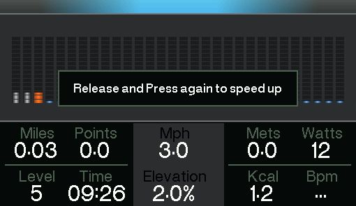
                                                                         1             9.5 Speed Confirmation 'Quick' Controls
Three-Step                                                                             (Console 5.0 CV)
Confirmation                                          - Quick Control set to 3.2 kph
                                                      - Quick Control set to 6.4 kph
                                                      - Quick Control set to 9.7 kph   When the 'Quick' Controls Panel Speed buttons are
                                                                                       pressed [See Figure Q]; before the Running Belt
                                                                                       will speed-up, an on-screen confirmation
                                                                                       instruction is shown. The User must follow the on-
                                                                                       screen instruction to allow the Running Belt to
                                                                                       increase its speed.
                                                                         2
                                                                                       In any event where the User feels unable to keep
                                                                                       up with the pace of the Running Belt and considers
                                                                                       themselves unable to reduce the Treadmill's speed
                                                                                       quickly, the User has three safe methods available
                                                                                       to stop the Treadmill:

                                                                                       1. Use (6.1) 260G 'Quick' Controls buttons (see
                                                                                       page 20)
                                                                                       2. Use (9.3 & 9.4) Emergency Stop Magnet/Safety
                                                                                       Clip (see pages 31 & 32)
                                                                                       3. Use (9.7) Emergency Dismount (see page 35)

                                                                         3
                                                                                              Warning:

                                                                                       When leaving the Treadmill always ensure that the
                                                                                       Stop button has been pressed, and that the Belt
                                                                                       has come to a halt!!

               Assembly, Operation & Parts Manual   G-Range                            CV                  Pg 33
General Safety Precautions (Continued)
Figure R
                                                                                                                                                                      1   9.6 Speed Confirmation 'Quick' Controls
Three-Stage                                                                                                                                                               (Console 6.0 CV)
Confirmation                                                                                                                         - Quick Control set to 3.2 kph
                                                                                                                                     - Quick Control set to 6.4 kph
                                                                                                                                     - Quick Control set to 9.7 kph       When the 'Quick' Controls Panel Speed buttons are
                                                                                                                                                                          pressed [See Figure R]; before the Running Belt
                                                                                                                                                                          will speed-up, an on-screen confirmation
                                                                                                                                                                          instruction is shown. The User must follow the on-
                                                                                                                                                                          screen instruction to allow the Running Belt to
           None           IPTV        iPod      Apps                                                          Volume           Settings
                                                                                                                                                                      2   increase its speed.
                                                                                                             Workout        Entertainment
                                                                                                                                                                          In any event where the User feels unable to keep
                                                                                                                                                                          up with the pace of the Running Belt and considers
                                                                                                              Increase speed to                                           themselves unable to reduce the Treadmill's speed
                                                                                                                  9.7          kph                                        quickly, the User has three safe methods available
                                                                                                                       OK                                                 to stop the Treadmill:
                  Level                Energy          Power           Time            Distance   Calories             Speed

                                                                   30:00                                                                                                  1. Use (6.1) 260G 'Quick' Controls buttons (see
                  0.0                 0.0              0.0                             0.00         0              0.0
                                                                       0                                                                                                  page 20)
                                 %       Mets          watts           bpm               km         kcals                             kph
                                                                                                                                                                          2. Use (9.3 & 9.4) Emergency Stop Magnet/Safety
                                                                                                                                 23JUL
                                                                                                                                                                          Clip (see pages 31 & 32)
                                                                                                                                  23JUL
                                                                                                                                 01:30
                                                                                                                                  01:30

                                                                                                                                                                          3. Use (9.7) Emergency Dismount (see page 35)
                                                                                                              Increase speed to                                       3
                                                         ACCEPTING SPEED                                          9.7          kph

                                                         In the latest software, the                                   OK                                                        Warning:
                                                         swipe acceptance button has
                                                         been replaced with a simple
                                                         OK button to confirm the                                                                                         When leaving the Treadmill always ensure that the
                                                         speed selected.
                                                                                                                                                                          Stop button has been pressed and that the Belt
                                                                                                                                                                          has come to a halt!!

                                     Assembly, Operation & Parts Manual                                                                     G-Range                       CV                  Pg 34
General Safety Precautions (Continued)
Figure S
                                                             9.7 Emergency Dismount
Emergency Dismount
                                                             Never mount or dismount the Treadmill while the
                                                             Running Belt is moving. Use the Handrails
                                                             whenever additional stability is required. In case of
                                                             an emergency, such as tripping, grasp the
                                                             Handrails, and place the feet on the Treadplates
                                                             [See Figure S].

                                                             In any event where the User feels unable to keep
                                                             up with the pace of the Running Belt, and unable to
                                                             reduce its speed quickly enough, the User is to be
                                                             instructed to grasp the Handrails, and place their
                                                             feet on the Treadplates.

                                                             Note:

                                                             The Emergency Stop Safety Clip (9.3) must
                                                             ALWAYS be worn.

              Assembly, Operation & Parts Manual   G-Range   CV                    Pg35
10 Installation
10.1 Location

Select a suitable location for the PULSE FITNESS Run Treadmill before moving it. The site you choose should meet the following requirements:

Ÿ   A flat, level and clean surface.
Ÿ   Close to a suitable power socket.
Ÿ   Well away from sources of water (or other liquids) or away from areas that are subject to condensation.
Ÿ   Away from direct sunlight (this can make it difficult to view the screen).
Ÿ   Leave a free space of at least 2m / 6.5ft at the rear of the machine.

Note: The Treadmill is not suitable for outdoor use.

If the chosen surface is carpet then the Treadmill can be pushed to the desired position on its front wheels (this is a two person procedure).
However, if the surface is more resistant, or the treadmill has to be lifted and lowered into place, then 6 people will be required.

                                                              CAUTION
                         This equipment is heavy! We do not recommend attempting to lift it without assistance, at least
                                              6 people should lift the Treadmill when necessary.

                                       NEVER attempt to lift the Treadmill by the Console or the Handrails.

                    Assembly, Operation & Parts Manual               G-Range                  CV                    Pg36
Installation (Continued)
Figure U
                                                                                       10.2 Feet Adjustment
Feet Adjustment
                                             WARNING                                   Once the Treadmill has been sited you must ensure
                                                                                       that it is stable. If there is even a slight rocking
                              When installing or adjusting any piece of PULSE          motion or the unit is not stable, determine which
                              FITNESS equipment , DO NOT leave any adjustment          foot is not resting on the floor. If necessary, adjust
                              devices projecting which could cause injury to a third   the height of the feet to compensate for any un-
                              party.                                                   evenness in the floor. Turn the feet to the left or
                                                                                       right to increase or decrease the height as
                                                                                       appropriate. [See Figure U]. When satisfied,
                    Locknut
                                                                                       securely fasten the locknut against the Feet Strut.

                                                                                       Place the front roller guides under front wheels.
                                                                                       This is a 3 person procedure and great care should
                                                                                       be taken when fitting. [See Figure T].
Figure T
Roller Guides                                                                          Note: It is extremely important that the feet are
                                                                                       correctly adjusted for proper operation. An
                                                                                       unbalanced unit may cause Running Belt
                                                                                       misalignment. A spirit-level is recommended to
                                                                                       ensure proper levelling.

                  Assembly, Operation & Parts Manual             G-Range               CV                    Pg 37
Installation (Continued)
Figure V
                                                                                 10.3 On/Off Switch
On / Off Switch                                             ON/OFF
                                                            Switch               The Treadmill is delivered with a power cable which
                                                                                 has a moulded plug already fitted. Plug the
                                                                                 Treadmill into a suitable mains socket and then
                                                                                 switch on the power.

                                                                                 Switch on the Treadmill via the on/off (I / O) switch
                                                                                 mounted at the front of the machine. [See Figure
                                                                                 V]. The Console display should illuminate and
                                                                                 display a regularly repeating start up message.
                                                                                 This indicates that the Treadmill is now ready for
                                                                                 use.

                                                                                 NOTE: If the Treadmill is not going to be used
                                                                                 straight away, then switch off and remove the 13A
                                                                                 plug from the socket.

                        CAUTION
Ensure that the mains cable is routed in such a way that it does not
create a potential hazard to users of the Treadmill or others persons in
the vicinity.

                     Assembly, Operation & Parts Manual                G-Range   CV                    Pg 38
11 How to Adjust and Tension the Running Belt
        Figure W
                                                                        11.1 Running Belt Alignment
        Running Belt Alignment
                                                                        Do not move the Treadmill, or place hands under
                                                                        the Treadmill while it is plugged into an electrical
                                                                        outlet!

                                                                        Once the Running Belt is aligned, the overall
                                                                        tension can be checked to make sure that it does
                                                                        not slip on its Rollers, this is explained in section
                                                                        11.2 and 11.3.

                                                                        Note: It is extremely important that the Treadmill is
                                                                        correctly levelled prior to any tracking adjustments.
                                                                        An unstable unit may cause Running Belt
                                                                        misalignment.

                                                                        Before proceeding, it is helpful to realise that each
                                                                        adjustment made to one side of the Roller must be
                                                                        met with an equal and opposite adjustment to the
                                                                        other side of the Roller to maintain an ideal belt
                                                                        tension at the pivot point.

                                                                        If the Running Belt slips, use an 8mm / 5/16” Allen /
                                                                        Hex Key wrench to adjust both the right and left
                                                                        tension bolts.

Note:

There is a maximum of 22mm lateral movement for the belt.

                         Assembly, Operation & Parts Manual   G-Range   CV                    Pg 39
How to Adjust and Tension the Running Belt (Continued)

 11.2 Tracking (Centring) a Running Belt

 Note: Two people are needed to perform this procedure.

 a. Locate the two access holes to the Running Belt tensioning bolts on each of the rear Roller End Caps [See Figure W].

 b. One person stands on the side rails of the Treadmill and straddles the Running Belt. This person presses GO and sets the Belt
 speed to 5Kph / 3.1Mph.

 c. If the Running Belt has moved to the right, the second person turns the right tension bolt a quarter-turn clockwise and then turns the
 left tension bolt a quarter-turn counter-clockwise to make the Running Belt track back to the centre of the roller.

 If the Running Belt has moved to the left, turn the left tension bolt a quarter-turn clockwise and then turn the right tension bolt a quarter-
 turn counter-clockwise to make the Running Belt track back to the centre of the roller.

 Note: If the Running Belt has moved as far as to the edge of the Roller (either right or left side), it must be re-centred per the above
 procedure.

 d. Repeat the adjustments until the Running Belt appears centred. Allow the machine to continue running for several minutes at 5Kph /
 3.1Mph to observe if tracking remains stabilised.

 Note: Do not exceed one full turn of the adjusting screws in either direction. If after one full turn the Running Belt does not track
 properly, contact Pulse Fitness Global Service Team. Do not over tighten the tensioning bolts while making belt adjustments. Over
 tightening of bolts may over stretch and damage the Running Belt or Roller.

            Assembly, Operation & Parts Manual                G-Range                   CV                     Pg40
How to Adjust and Tension the Running Belt (Continued)

 11.3 Tensioning an Existing Running Belt

 a. Press GO and operate the treadmill for five minutes at 5Kph / 3.1Mph.

 Note: DO NOT RUN OR WALK ON THE RUNNING BELT.

 b. Reduce the speed to 3.0Kph / 1.9Mph. Walk on the Treadmill. Tightly grip the Handrails and apply force with feet on the Running
 Belt near the Motor Cover against the moving Belt direction. If the Belt slips, continue to Step 3. If it does not slip, the tension is
 correct.

 c. Using the STOP key, stop the Treadmill. Turn the Running Belt tensioning bolts a quarter-turn clockwise for each side.

 d. Repeat STEPS 2 and 3 until the belt no longer slips. Do not exceed one full turn (four quarter turns) per side when adjusting the Belt
 tensioning bolts.

 e. Press GO, operate the Treadmill at 3.0Kph / 1.9Mph and check to ensure proper tracking. If the Running Belt drifts to the left or right
 see Tracking (Centring) an Existing or New Running Belt on the previous page.

 Re-check the tension of the Running Belt, do not over tighten the tensioning bolts while making belt adjustments. Over tightening of
 bolts may over stretch and damage the Running Belt or Roller bearings. Do not exceed one full turn of either bolt in either direction.

 NOTE: Take care not to touch the Running Belt during this procedure.

           Assembly, Operation & Parts Manual                G-Range                  CV                    Pg 41
12 Cleaning & Maintenance
  12.1 Preventive Maintenance Tips

  PULSE FITNESS products are backed by engineering excellence and the reliability of the Global Service Team. The Treadmill is one
  of the most rugged and trouble-free pieces of exercise equipment on the market today.

  Note: Safety can be maintained only if the equipment is examined regularly for damage or wear. Keep the equipment out of use until
  defective parts are repaired or replaced. Pay special attention to parts that are subject to wear, as outlined below.

  The following preventive maintenance tips will keep the PULSE FITNESS product operating at peak performance:
  Locate the product in a cool, dry place.
  Long fingernails may damage or scratch the surface of the Console; use the pad of the finger to press the selection buttons on the
  Console.

  12.2 Cleaning the Equipment

  Pulse Fitness Approved Cleaners (United States Availability Only)

  Two preferred cleaners have been approved by PULSE FITNESS reliability experts: PureGreen 24 (or equivalent) and Gym Wipes.
  Both cleaners will safely and effectively remove dirt, grime and sweat from equipment. PureGreen 24 (or equivalent) and the
  antibacterial formula of Gym Wipes are both disinfectants that are effective against MRSA and H1N1. PureGreen 24 (or equivalent) is
  available in a spray which is convenient to use. Apply the spray to a micro fibre cloth and wipe down the equipment. Use PureGreen
  24 (or equivalent) on the equipment for at least 2 minutes for general disinfection purposes and at least 10 minutes for fungus and
  viral control. Gym Wipes are large, durable pre-moistened wipes to use on the equipment before and after workouts. Use Gym
  Wipes on the equipment for at least 2 minutes for general disinfection purposes.

  Contact PULSE FITNESS Global Service Team to order these cleaners +44 (0)1260 294600 or email:
  global.service@pulsefitness.com.

            Assembly, Operation & Parts Manual              G-Range                  CV                   Pg 42
Cleaning & Maintenance (Continued)

       12.3 Compatible Cleaners

       DO NOT use water based solutions (on the following): Clean the display console, all exterior surfaces and the frame with a mild, non-
       abrasive silicon based household cleaner. Apply via a soft micro fibre cloth. Apply the cleaner to the cloth before cleaning. DO NOT
       use ammonia or acid based cleaners. DO NOT use abrasive cleaners. DO NOT use paper towels. DO NOT apply cleaners directly to
       the equipment surfaces.
       DO use water based solutions (on the following): Clean the upholstery and handgrips with a mild soap and water solution.
Figure X
Preventive Maintenance Schedule                                                          12.4 Preventive Maintenance Schedule
     Item                               Weekly          Monthly             6-Months
     Console Overlays
                                                                                         Check operation of the emergency stop system
                                        Clean
     Bottle Holders / Accessory Trays   Clean           Inspect                          once a week.
     Console Mounting Bolts                                                 Inspect      Check the operation of the stop button once a
     Hardware                                                               Inspect      week.
     Frames                             Clean                               Inspect      Inspect and vacuum the area directly surrounding
     Plastic Covers                     Clean           Inspect             Inspect
                                                                                         and under the unit regularly.
     Handpulse Sensors                  Clean/Inspect
     Running Belt                       Inspect
                                                                                         Vacuum around the Belt regularly to keep debris
     Machine Level                      Inspect*                                         from accumulating.
     Emergency Stop                     Clean/Inspect                                    Inspect exterior parts regularly for wear, particularly
     Motor Cover                        Clean           Vacuum/Clean                     the Belt, Deck and Power Cord.
     Motor Electronic Compartment                                           Inspect      Check to make sure the unit is properly levelled.
     Drive Belt                                                             Inspect
                                                                                         Check the position (centring) of the Belt.
     Foot Adjusters                                     Inspect / Adjust
                                                                            Inspect
                                                                                         Clean the Console and all exterior surfaces with an
     Front & Rear Rollers
     Treadplates                        Clean           Inspect                          approved or compatible cleaner (see PULSE
     Handrails                          Clean                               Inspect      FITNESS Approved Cleaners) and a micro fibre
     Front Handlebar                    Clean                               Inspect      cloth.
     * Use spirit level

                      Assembly, Operation & Parts Manual                   G-Range       CV                    Pg 43
Cleaning & Maintenance (Continued)

   WARNING: Failure to carry out maintenance on the equipment as per this manual could result in serious injury and void your warranty.
   Please ensure all publications supplied with PULSE FITNESS equipment are read and understood.

   12.5 How to Obtain Product Service

   1. Verify the symptom and review the operating instructions. The problem may be unfamiliarity with the product and its features and
      workouts.
   2. Locate and write down the serial number of the unit which is located on the back of the unit near the foot rail.
   3. Contact Pulse Fitness Global Services Team (refer to page 02).

             Assembly, Operation & Parts Manual              G-Range                 CV                   Pg 44
13 Specifications
  13.1 - PULSE FITNESS Run (Low Impact 'Elevation' Treadmill) specifications:

  Designed use: Heavy/Commercial.

  Motor power: 3.0HP (5.0HP Peak).

  Drive: Rhymebus AC Motor.

  Power requirements:           EU - 220-240V, 50Hz, 13A, 1500W.
                                US - 110-120V, 60Hz, 15A.

  Mains powered: Series 1, 2 & 3.

  Central ‘Quick’ control console featuring speed and elevation adjustments: Series 2 & 3.

  Stop systems: Red and Yellow magnetic ‘kill-cord’ Emergency Stop System and Programme Stop Push Button raised and
  prominently positioned.

  Speed range (kph/mph): 0.5 - 24.1Kph / 0.3 - 15Mph.

  Speed increments: 0.1kph / 0.1mph increments.

  Elevation range: 0%-15%.

  Elevation increments: 0.5%.

  Deck type (cm/"): 2.4cm / 15/16” Reversible medium density fibreboard.

  Shock Absorption System: Low impact sprung.

            Assembly, Operation & Parts Manual              G-Range                  CV           Pg 45
Specifications (Continued)

 Waxing system: Self-lubricating Running Belt.

 Running Belt (cm/"): 152cm / 59 -3/16" Length x 54cm / 21-1/4" Width (between belt centres).

 Front Handrail: Ergonomically shaped, neoprene grips.

 Side Handrails (cm/"): 65cm / 25-9/16" x 15.5cm / 6-1/16" Long, flared, cantilevered, over-moulded grips.

 Workout pause with auto-reset: Series 2 & 3.

 High contrast reflective belt guides: Optional.

 Step-up box: Optional

 Twin removable storage buckets/cup holders: Series 1, 2 & 3.

 Integrated device storage tray: Series 1, 2 & 3.

 Rollers (cm/"): 10.2cm / 4" diameter, precision-crowned, front and back.

 Operating temperature: from 5oC to +30oC (from +41oF to +86oF).

 Telemetry: Equipped for heart rate telemetry reading using a chest strap. 5kHz non-coded transmission Polar® Telemetry
 Handpulse Sensors: DSP Handpulse Sensors (Digital Signal Processing).

 LAN (Ethernet or WiFi): Series 3 ONLY

 Integrated Television Tuner: Series 2 & 3 ONLY

           Assembly, Operation & Parts Manual               G-Range                 CV                        46
                                                                                                             Pg
Specifications (Continued)

 13.2 Physical Dimensions (L x H x W)

 Length (cm/"): 214mm / 84-1/4"
 Height (cm/") 0% elevation: Series 1 & 2 = 160cm / 63", Series 3 = 163cm / 64-3/16"
 Height (cm/") 15% elevation: Series 1 & 2 = 196cm / 77-3/16", Series 3 = 199cm / 78-3/8"
 Width (cm/"): 88cm / 34-5/8"

 Step-Up Height: 27.5cm / 10-13/16"

 13.3 Weight (kg/lbs)

 Machine Weight (kg/lbs): Series 1 = 219.5kg / 484lbs. Series 2 = 220kg / 485lbs. Series 3 = 225kg / 496lbs.
 Maximum User Weight (kg/lbs): 160kg / 353lbs.

 13.4 Console

 Screen:   Series 1 - 17.8cm / 7" Integrated High Contrast Colour Display. 16:9 Aspect Ratio. 512x300 Resolution.
           Series 2 - 25.7cm / 10-1/8" Integrated High Contrast Colour Display. 16:9 Aspect Ratio. 512x300 Resolution.
           Series 3 - 47cm / 18-1/2" Integrated High Contrast Capacitive Multi-Touch Colour Display. 16:9 Aspect Ratio. 1366x768
                      Resolution.

 Headphone Jack: Stereo 3.5mm, Series 2 & 3 ONLY

 Integrated Television Tuner: Series 2 & 3 ONLY
           EU - Analog – PAL. Digital - DVB-T (Freeview). IPTV: MPEG-2 Standard Definition; MPEG -4 pt10 AVC/H.264 Standard
           Definition. Radio: Digital - DVB-T.
           US - PAL/SECAM and NTSC require separate tuners. NTSC tuner supports NTSC-Japan, NTSC-HRC, NTSC-M, NTSC-N.
           NTSC also supports PAL-M and PAL-N which are unique PAL encodings for Argentina, Brazil, Paraguay and Uruguay.
           PAL/SECAM tuner supports PAL, PAL-M, PAL-N, SECAM-B/G and SECAM-D/K.

           Assembly, Operation & Parts Manual             G-Range                 CV                   Pg 47
Specifications (Continued)

 Workout Programmes:
          Series 1 - Quick Start, Goals (Time; Distance; Calories), Marathon mode, Pacer (Time and speed; Time and distance;
          Speed and distance), Profile: X-country (easy, moderate, advanced), Aerobic (easy, moderate, advanced), Hill climb (easy,
          moderate, advanced), Intervals (easy, moderate, advanced), Random (easy, moderate, advanced), Rockport fitness test
          with V02 result, Variable cool down with manual override.
          Series 2 - Quick Start, Optional - E-Scape virtual workouts (road, lake. valley, beach), Goals (Time; Distance; Calories),
          Marathon mode, Pacer (Time and speed; Time and distance; Speed and distance), Profile: X-country (easy, moderate,
          advanced), Aerobic (easy, moderate, advanced), Hill climb (easy, moderate, advanced), Intervals (easy, moderate,
          advanced), Random (easy, moderate, advanced), Rockport fitness test with V02 result, Variable cool down with manual
          override.
          Series 3 - Quick Start, E-Scape virtual workouts (road, lake. valley, beach), Goals (Time; Distance; Calories), Marathon
          mode, Pacer (Time and speed; Time and distance; Speed and distance), Profile: X-country (easy, moderate, advanced),
          Aerobic (easy, moderate, advanced), Hill climb (easy, moderate, advanced), Intervals (easy, moderate, advanced), Random
          (easy, moderate, advanced), Custom profile builder, Rockport fitness test with V02 result, Variable cool down with manual
          override.

 Languages available:
         Series 1 - English (UK).
         Series 2 - Chinese, English (UK), French, German, Italian, Japanese, Russian, Spanish & Welsh.
         Series 3 - Chinese, English (UK), German, Japanese, Russian & Welsh.

 Workout Displays:
          Series 1 - Profile display with level indicator, Track display with level indicator (pacer mode only), Time elapsed/remaining
          (depending on program), Distance elapsed/remaining (depending on program), Speed, Elevation, Calories used, Watts,
          Heart rate, METs, User selectable/management programmable units (imperial/metric), User selectable/management
          programmable language.
          Series 2 - Profile display with level indicator, Track display with level indicator (pacer mode only), Time elapsed/remaining
          (depending on program), Distance elapsed/remaining (depending on program), Speed, Elevation, Calories used, Watts,
          Heart rate, METs, User weight entry (automatic when used with PulseMove Professional), User selectable/management

           Assembly, Operation & Parts Manual                G-Range                 CV                    Pg 48
Specifications (Continued)

          programmable units (imperial/metric), User selectable/management programmable language.
          Series 3 - Profile display with level indicator, Track display with level indicator (pacer mode only), Time elapsed/remaining
          (depending on program), Distance elapsed/remaining (depending on program), Speed, Elevation, Calories used, Watts,
          Heart rate, METs, Extendable workout goal, User weight entry (automatic when used with PulseMove Professional), User
          selectable/management programmable units (imperial/metric), User selectable/management programmable language.

 USB:     Series 1 - Service Port - For software updates & Smartphone device charging.
          Series 2 - Service Port - For software updates & Smartphone device charging.
                     Optional - with supplied iPhone®/iPod®/iPad® 30-pin connector.
          Series 3 - Service Port - For software updates & Smartphone device charging.
                     Optional - with supplied iPhone®/iPod®/iPad® 30-pin or Lightning connector.
                     Optional - with supplied AndroidTM Micro USB connector, just for charging.

 Audio feedback: Series 2 & 3 - Optional

           Assembly, Operation & Parts Manual               G-Range                  CV                    Pg 49
14 Parts Lists & Exploded Diagrams
Figure Y                                                                                                                                                                                                                                                                                                                                         14.1 Parts Lists & Exploded Diagrams
Parts Lists & Exploded Diagrams
                                                                                                                                                                                                                                                                                                                                                 Details on both Parts Lists & Exploded Diagrams
                                                                                                                                                                   266
                                                                                                                                                                                                                                                                                                                                                 for Series 2 & 3 260G Treadmills, please refer to
                                                                                                                                                   267
                                                                                                                                                                                                                                                                                                                                                 documents:
                                                                                                                               200 198

                                                                                                                                             199

                            177
                                                                                                                                                                    261
                                                                                                                                                                                                                                                                                                                                                  135-1094-03-* Exploded Dia. (Short Version)
                                              163

                                                                                                                                     128
                                                                                                                                                                         259
                                                                                                                                                                                                                                                                                                                                                  135-1093-01-* Series 2 (Console 5.0 CV)
                                                                                                                                                       196

                                                                                                                                                                                                                                                                                                                                                  135-1093-02-* Series 3 (Console 6.0 CV)
                                                     162
                                                                                                                                                 161

                              281         257

                                                                                                                                                 160                                                                                                                                                        247
                                                                                                                                                                                                                            123                                                                243
                                                                                                                                                                                                                                                                                                                               249
                                                                                                                                                                     126
                                                                                                                                                                                                                                         112

                                                             214                                                               163
                                                                   215                                                                                                                                                             121                            112
                                    215
                                                                                                                         162                                                                                                                                            298
                                                           242                                                                                           129                                                                                   124
                                                                                                                                                                                                                                  103
                            214
                                                                                                                                                                                                                                         121
                                                                                                                                                                                                                                                                               30
                                                                                                                                                                                                                                                   112                                                                    213
                                                                                                                                                                                                                                                                                    270                                                    253
                                                                                                                                                                                                                                                                              13
                                                                                                             153 151                                                                                                              295                                                                                           241
                                                                                                                                                                                                                                        296
                                                                                                                                                             159                                                                                                                               255
                                                                                                                                                                                                                                                     297
                                                                                                                                                                                                                                               1                                                      202
                                                                         191                           144                                                                127
                                                                                                                                                                                                                                                                                                              203
                                                                                                                                                                                                                                                                        6
                                                                                                                                                                                                                                                                                          202
                                                                                                                                                                                            205                     113                                                       17                                    202
                                                                                                                                                                                                                                                                                                 252
                                                                                                                                                                                274 236 206
                                                                                                                                           279                                                                                    120                                                     16            201
                                                                                                 197                                                                                                                                                                                                                                 201
                                                                                                                                                   24
                                                                                                                                                                                                                                                                        19
                                                                                                                                                                                                              272                                                                                18
                                                                                                               145                                 230                    31                            211
                                                                                                                                                                                 278                                                                                                                                      23
                                  111                                                                                                                                                                                                                                                                         20
                                                                                                       122                                                                              211 208                                                                                                                                 203
                                                                                                                                                                                                    210        268                                         164
                                                                                                               11
                                                                                                 216                                                                                              204                                                                                                  19
          256                                                                        122                                                                                                                                  207
                                                                                                                                                                                                                                                                                                                     21
                                                                                           238                                                    240                                                          269
                                                                   247         121

                                                                                                                                                                                                        251
                                                                                                                                                                                                                                                                 287
                                                                                                                       240
                                                                                                                                                                                        246

                                                                                                                                                                                 219

                                                    211                                                                                                                                     227
                                                                                                                                                                                                    229
                                               232                        105
                                        271
                                                                                                                                                                                104
                      239                                                                                                                                                                     228                   225
                                                           254
                                                                     231                                                                                                                                                                                                             244
                246                                                                                                                                                                         112
                                                                                                                                                                     121

                                    22    246                                                                    25                                                                   102                     101
                                                      245

                                                                           NB: Image for illustration only

                                  Assembly, Operation & Parts Manual                                                                                                                                                                                                   G-Range                                                                   CV                   Pg 50
15 User Notes

     Assembly, Operation & Parts Manual   G-Range   CV    51
                                                         Pg
User Notes (Continued)

      Assembly, Operation & Parts Manual   G-Range   CV    52
                                                          Pg
135-1572-4

Pulse Fitness,
Radnor Park, Greenfield Road,
Congleton, Cheshire, CW12 4TW.
England, United Kingdom
Tel: +44(0)1260 294600
Fax: +44(0)1260 299282
Email: global.service@pulsefitness.com

© 2018 Pulse Fitness Ltd. All rights reserved. Pulse Fitness, is a registered trademark. Any use of these trademarks, without the express written consent of Pulse Fitness
or the corresponding companies is forbidden. iPhone® & iPod® are registered trademarks of Apple Inc. Polar® is a registered trademark of Polar Electro Inc.
You can also read