EVALUATION OF SHUNT DISTANCE IN RESISTANCE SPOT WELDING - DANIEL FREDRIKSSON MILOU GÖRANSSON - DIVA
←
→
Page content transcription
If your browser does not render page correctly, please read the page content below

DEGREE PROJECT IN TECHNOLOGY,
FIRST CYCLE, 15 CREDITS
STOCKHOLM, SWEDEN 2020

Evaluation of Shunt Distance
in Resistance Spot Welding
DANIEL FREDRIKSSON

MILOU GÖRANSSON

KTH ROYAL INSTITUTE OF TECHNOLOGY
SCHOOL OF INDUSTRIAL ENGINEERING AND MANAGEMENT
Abstract
The purpose of this study was to generate a greater understanding of how the shunt distance affects the
shunting phenomena which occurs when working with resistance spot welding (RSW). Shunting
affects the quality of the weld and the goal of the study was to create guidelines for RSW to minimize
its impact on the weld quality. In order to minimize waste from production and to reduce the welding
time there is need for understanding of what the shunt effect depends on. To evaluate what impact the
shunt distance will have on the weld, two different experiments were performed. In the first
experiment, a one-dimensional welding lobe was manufactured for various materials and the current
range was compared over three different shunt distances. The second experiment consisted of welding
with a constant current on different shunt distances to investigate how this would impact the second
weld performed in the welding sequence. A range of different steel grades and sheet thicknesses was
used in the experiments to further explore what impact different material properties will have on the
shunt effect. The result showed that the shunt distance has little impact on the acceptable weld-current
range, with minor deviations. However, the shunt distance will affect the size of the shunted weld,
which decreases as the shunt distance is reduced. Overall, the data collected in this study is not
expansive enough to make guidelines that could be implemented in today´s industry. The phenomena
of shunting require more data to fully be understood.

Keywords
Resistance spot welding, RSW, Shunt effect, Shunting, Shunt distance, One-dimension
welding lobe.

Sammanfattning
Syftet med denna studie var att skapa en större förståelse för hur shuntavståndet påverkar det
shunt-fenomen som uppstår när man arbetar med punktsvetsning (RSW). Shuntning påverkar svetsens
kvalitet och målet var att skapa riktlinjer för arbete med RSW för att minimera
shunt-effektens påverkan på svetsen. I syfte att kunna minimera spill i produktionen samt att minska
svetstiden krävs det förståelse av vad shunt effekten beror på. För att utvärdera vilken påverkan
shuntavståndet kommer att ha på svetsen utfördes två olika experiment. I det första experimentet
skapades en endimensionell svetslob för varje material och det genererade strömintervallet jämfördes
över tre olika shuntavstånd. Det andra experimentet bestod av svetsning med en lika stor ström vid
olika shuntavstånd för att undersöka hur detta skulle påverka den andra svetsen. En rad olika stålsorter
och plåttjocklekar användes för att ytterligare se vilken påverkan dessa faktorer kommer att ha på
shunt-effekten. Resultatet visade att shuntavståndet hade liten inverkan på det acceptabla
svetsströmintervallet, med mindre avvikelser. Emellertid påverkar shuntavståndet storleken på den
shuntade svetsen genom att storleken minskar när shuntavståndet minskas. Sammantaget räcker inte
de uppgifter som samlats in i denna studie för att skapa riktlinjer som skulle kunna implementeras i
dagens industri, utan det krävs mer data för att fullständigt kartlägga shunt-effekten.

Nyckelord
Punktsvetsning, RSW, Shunt effekt, Shuntning, Shuntavstånd, Endimensionell svetslob.
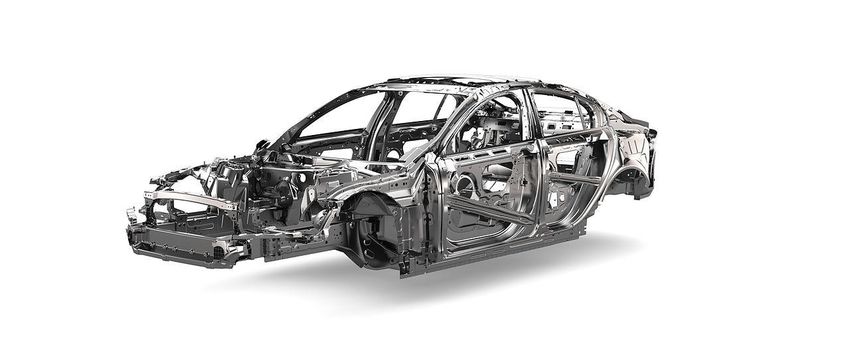
Table of content

1. Introduction ............................................................................................................................ 1

 1.1 Purpose and objectives of the project ............................................................................... 2

 1.2 Boundaries of the study .................................................................................................... 3

 1.3 Ethical and Environmental impacts .................................................................................. 3

2. Resistance spot welding ......................................................................................................... 4

 2.1 Resistance spot welding parameters ................................................................................. 5

 2.1.1 Weld current ............................................................................................................... 5

 2.1.2 Weld time ................................................................................................................... 5

 2.1.3 Electrode force ........................................................................................................... 6

 2.1.4 Other welding parameters .......................................................................................... 6

 3.1 Previous investigations ..................................................................................................... 7

4. Experimental method ............................................................................................................. 9

 4.1 Experimental equipment ................................................................................................... 9

 4.2 Materials ......................................................................................................................... 10

 4.3 One-dimension welding lobe .......................................................................................... 11

 4.3.1 Welding process parameters .................................................................................... 12

 4.4 Welding with set current................................................................................................. 12

 4.4.1 Welding process parameters .................................................................................... 12

5. Results .................................................................................................................................. 13

 5.1 One-dimension welding lobe .......................................................................................... 13

 5.1.1 DP600 ...................................................................................................................... 13

 5.1.2 Boron steel ............................................................................................................... 15

 5.1.3 Forta H1000 Stainless 1.5 mm ................................................................................. 16

 5.1.4 Forta H1000 Stainless 2.0 mm ................................................................................. 18

 5.1.5 Boron blasted steel ................................................................................................... 19

 5.1.6 Compilation of results .............................................................................................. 21
5.2.1 Boron blasted steel ................................................................................................... 21

 5.2.1 DP800 steel .............................................................................................................. 22

 5.2.2 Compilation of results .............................................................................................. 22

6. Discussion ............................................................................................................................ 23

 6.1 One-dimension welding lobe .......................................................................................... 23

 6.1.1 Sources of error ........................................................................................................ 24

 6.2 Welding with set current................................................................................................. 24

 6.2.1 Sources of error ........................................................................................................ 25

7. Concluding remarks ............................................................................................................. 26

8. Further study ........................................................................................................................ 27

9. Acknowledgements .............................................................................................................. 28

10. References .......................................................................................................................... 29
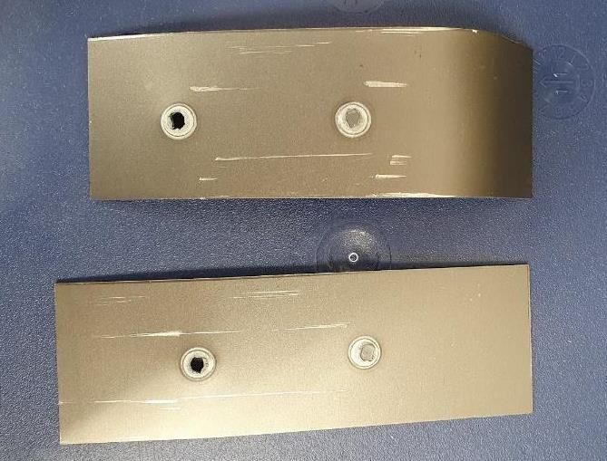
1. Introduction
With an increasing development towards more lightweight vehicles, the material combination used in
the automotive industry are changing from mostly only using low carbon steel to using a mix of low
carbon and high strength steel. This change of material usage creates new demands regarding the
joining method in the production. A well-adapted joining method can be used to assemble the material
in an efficient and reliable manner. There are many different types of welding techniques in use today,
though the most extensively used method in the automotive industry is resistance spot welding (RSW).
The stage in automotive manufacturing where most of the welding takes place is when creating the
body-in-white (BIW), a sheet metal welded structure, shown in Figure 1. A typical steel body-in-white
contains around 5000 spot welds which creates high demands concerning the choice of welding
technique. [1]

 Figure 1. Body-in-white, an early state in the manufacturing process of a car. [2]

The reasons for the extensive use of resistance spot welding is due to the low cost, short weld time,
and the high automation capabilities which eliminates human interference. Eliminating human
interference in turn minimizes errors and provides the method with a wide range of optimization
parameters. Resistance spot welding is for the most part performed by robots and the weld is
completely internal which removes the need for further treatment. RSW is a welding technique where
the process works by applying an electric current through two or more sheets of metal that are clamped
together by a pair of electrodes. As the current is passing through the sheets, the resistance of the
circuit cause generation of heat energy. The heat energy (Q) is a function of the current (I), resistance
(R) and time (t) as defined by Joule’s law, seen Equation 1. [1]

 = 2 (Eq. 1)

The generation of heat energy, mainly caused by the resistance, melts the welding area between the
metal sheets. When the current is stopped and no further heat energy is generated, the temperature will
decrease, and the metals will solidify as merged. The method is greatly dependent on the electrical and
thermal conductivity properties of the materials in use. [3]

To achieve a repeatable weld result and a short weld time there is a need for greater understanding of
how the distance between the welds, also called the shunt distance, affects the result. When working
with RSW on a metal piece, welds are continuously produced within the same region and therefore a
shunt effect occurs. [4]

 1
The shunt effect is described as a parallel path where the current will flow through instead of the
intended welding point, see Figure 2. This results in that an insufficient amount of heat generation,
resulting in an increased weld time, decreased size of nugget* and a possibly failed weld. As the
industry strives for shorter production times, reduction of unnecessary quality testing, and a more
reliable welding result it is not efficient to use a trial and error-based approach to solve these
problems. [4]

*A nugget is the molten metal between the sheets that solidifies into the welding joint. [4]

Figure 2. Illustration of current going through the previous performed weld via the shunt path, also referred to as shunting.

To achieve these goals and optimize production, there is a need for guidelines of the RSW process for
the automotive industry production, to minimize the effect of shunting and thus create a more
consistent result of the weld. To obtain an efficient production, the effects of shunting must be
evaluated on a larger scale to understand what it depends on and how it can be accounted for.

1.1 Purpose and objectives of the project
The project aimed to create guidelines for optimizing the weld quality for RSW. This was achieved by
evaluating the RSW process, specifically by an investigation of the shunt effect and the shunt distance.
The project aimed to answer three research questions, which are stated below.

 ● How will the shunt distance affect the quality of the resistance spot weld?

 ● How do different material properties and process parameters affect shunting and the optimized
 shunt distance?

 ● How will the previous weld in a welding sequence impact the approved current range, when
 the shunt distance is changed?

 2
1.2 Boundaries of the study
The project investigated how to optimize the shunt distance to obtain a more reliable weld quality.
This was performed by experiments where the current and the weld spacing varied. This means that
this study did not focus on optimizing other welding parameters such as the electrode force or welding
time. In addition, the impact of material properties was discussed only partially, when it is deemed
relevant to answer the research questions. By limiting the project, the likelihood to concretely
understand the impact of the shunt effect increases.

1.3 Ethical and Environmental impacts
The focus of this study lies in understanding and minimizing the effects of shunting in resistance spot
welding thus making the question of ethical impacts not relevant for this report. The fact that RSW is
mostly used in the automotive industry means that the welding technique is a subject of ethical
impacts but due to the focus of this study being on the pure process and not the overall industry this
will not be further analysed in this report.

Greater knowledge of the shunt effect can help with the environmental impact in that industries would
reduce the number of discarded welds, and thereby minimize wasted production. This would lead to a
higher efficiency and drive the overall costs down. Furthermore, reducing the effect of shunting, a
lower current may be used in production, meaning that less energy will be used, resulting in a more
sustainable industry. This type of knowledge will be useful when developing or improving the
production further, with reduced number of samplings needed when changing material combinations.
The knowledge of how to account for the shunt effect would mean that less process optimization
would be needed for each change in material combination, thus reducing unnecessary material waste
and increasing the production rate.

 3
2. Resistance spot welding
Resistance spot welding is a form of liquid phase welding, the materials are locally heated to a liquid
state. By applying pressure, a fusion bonding will occur and by maintaining the pressure as the liquid
fusion cools, a joint is formed. [1] The spot weld will form due to resistance heating, generated by the
total electrical resistance (including contact and bulk resistivities*) between the welded sheets. [3] The
timeline for the RSW process can be seen in Figure 3, where two sheets are joined by firstly clamping
them together using an electrode pair. The current and resistance in the material generate heat, which
in turn melts the welding area between the sheets. When the current is shut off, and the material cools
down, the molten metal solidifies into a nugget. The electrodes keep the sheets clamped together
throughout the welding process to ensure a consistent joining and controlling the resistance in the
circuit; by applying a high pressure a lower resistance will be achieved and vice versa. [1]

*Resistivity being a material property that quantifies how strongly the material resists or conducts
electric current. [5]

 Figure 3. Illustration of the RSW process timeline.

The final properties such as strength, for a spot weld are dependent on the diameter of the nugget,
formed during welding. [1] To verify the quality of the weld, the nugget size is determined; this can be
made from a visual examination in combination with producing data visualization, such as a lobe- and
current range curve. Using one dimensional-welding curves can help determine the process stability,
with a bigger lobe- and current range curve showing a more stable process with higher quality. The
relationship between nugget size and weld time can be seen in the current range curve and the lobe
curve shows the process window of the current for producing acceptable nuggets. [6] The minimum
acceptable size of the nugget can vary depending on the requirements of the industry in question but is
approximately between 5√ and 4√ , where t is the sheet thickness in millimetre. [1] The maximum
nugget size is defined on the curves where the current reaches its maximum value before expulsion
occurs. Expulsion is the phenomenon when drops of molten metal eject from the sheets due to
formation of a too large nugget. This occurs under excessive heating or insufficient electrode force.
Some expulsion during the process in production is considered acceptable. However, welds that do
expulse are never approved and due to the risk of decreased strength this is often compensated by
producing additional welds. [6]

 4
There are different welding parameters that regulate the size of the nugget, including the weld current,
welding time and the applied force of the electrodes. Other impacting factors are surface coatings, the
contact area of the sheets and the design of the electrode tips. The setting of these parameters varies
for different types of materials and for each combination there are a range of different quantities of the
parameters required to produce acceptable welds. [1]

2.1 Resistance spot welding parameters
As previously mentioned, there are several different types of welding parameters that impact the weld
quality. The three process parameters with the greatest impact and that are the easiest to control during
the welding are; current, weld time and electrode force.

2.1.1 Weld current
The current in resistance spot welding is a very important variable. If the current is too low, the
formed nugget will decrease in size and may not reach the required size or lack the required strength.
On the other hand, if the current applied is too high, expulsion could occur which may result in an
unacceptable nugget quality and decreased size. The amount of current that is used varies for different
materials and applications. For steel, the optimized weld current should approximately
be 8-10 kA. [1]

In addition to the weld current, a pre-pulse of high current can be used before the actual welding
process begins. When using a pre-pulse, a better contact between the metal sheets can be achieved;
this is due to the removal of a coating layer or dirt and improving the contact area in cases of uneven
thickness. Pre-pulse can also improve the process if several sheets are being welded
simultaneously. [7]

2.1.2 Weld time
The duration of the welding process includes different intervals; squeeze time, weld time, hold time
and off time. Firstly, the squeeze time represents the duration needed to reach the desired electrode
force. Secondly, the current flows duration is called weld time. Thirdly, the duration while the weld
solidifies but the force is still applied is called hold time. Finally, the off time is the time needed for
the electrodes to move to the next weld in the welding sequence. These intervals can have different
durations to optimize the production, but the process can also be simplified by ignoring time intervals
without material impact on the total process duration. [6]

It is important to obtain a short weld time while succeeding to produce a nugget of the required size.
The industry strives for a high production rate, which makes seeking shorter weld times of great
importance. However, a too short weld time may not generate enough heat to form an approved weld
and a too long weld time may cause an unwanted expulsion. The weld time varies for different
materials, but for steel a typical weld time is approximately 200 ms. [6]

 5
2.1.3 Electrode force
The electrode force is one central parameter due to the importance of contact resistance between the
welded sheets; this is due to the need of satisfactory heat generation. A too high force will not generate
a high enough heat to melt the material and form an acceptable nugget size due to a decrease of the
electrical resistance of the contact area. A high force can also cause excessive deformation.
On the other hand, a too low electrode force may cause internal porosity and cracking of the nugget
after the welding. A low force may also create gaps between the sheets; this in turn can lead to
increased expulsions due to the generation of additional heat at certain points. [8]

A varying electrode force can be used during the process, but in the automotive industry the force is
usually set to a fixed value. Typically, the electrode force for automotive is approximately
3-6 kN. Using a higher electrode force will increase the amount of wear on the equipment which could
result in giving it a shorter lifetime. [8]

2.1.4 Other welding parameters
As one can imagine there are several other welding parameters that have an influence on the welding
quality, not least depending on which material that is being welded. For example, the electrical
resistivity, thermal conductivity, and heat capacity of the material that are being joined are all vital
variables. The surface condition of the material is also one parameter, for example welding
of materials with a zinc-layer requires longer weld time or higher current compared to uncoated
materials. [1] Geometric factors such as sheet thickness and fitting are also of importance. Other than
material properties, the resistance spot welding machine has its own parameters such as cooling water
flow, current type, electrode material, electrode degradation, and other design variables that will affect
the welding. [6]

 6
3. Shunt effect
When using resistance spot welding for multi-spot welding, a phenomenon called the shunt effect will
occur. The shunt effect implies that the electrical current intended to flow through the welded spot
instead passes through previously welded spots. Even though the pieces of material that are welded are
connected in other areas than the welded spot, the shunt effect does not occur as much there. This is
due to an oxide layer and lack of electrode pressure in these areas. The amount of current that flows
where it is not intended mainly depends on the previous welds, with respect to the number, size and
spacing between them. The spacing between the welds in a welding sequence are called the shunt
distance. [9] Figure 4 shows the shunt distance between the first weld (the shunt weld) and the second
weld (the shunted weld) in a welding sequence.

 Figure 4. Illustration of the shunt distance in a welded sample.

The difference in distribution of current to the welded spots is one consequence of the shunt effect
which causes inconsistencies in weld quality. Another consequence of the shunt effect is that due to
the differences in distribution of current, the distribution of heat will also vary between welds. This
causes a reduction in the diameter of the next formed nugget, which will affect the mechanical
properties of the weld. [9]

The shunt effect is complex; a multitude of other factors, such as welding current, welding time,
electrode force and geometry of the component all affect the mechanism. The material properties of
the welded material such as bulk resistance and surface conditions will also influence the result. [9]

3.1 Previous investigations
Although the impact of the shunt effect in RSW is complex and not completely understood, previously
experimental investigations have been made.

One of the first experimental studies of the shunt effect was performed in 1948 by Hard et al. and the
study developed a method for measuring the shunt path. The study also showed that when performing
a multi-spot-welding sequence, the tensional and shearing strength of the welds in said sequence
decreases a significant amount compared to when welding a single spot. [10]

 7
A two-part study including an experimental and theoretical investigation has been done by Wang et al.
The experimental study used different types of mild steel and included the effect of various factors
such as material, surface condition and welding schedule. A mild steel is a steel with a low carbon
content, making the material malleable and ductile. The conclusions of the study are that the distance
between the welds in a welding sequence is the most important factor when examining the shunt effect
and increasing this distance will have the biggest impact to avoid it. The surface condition of the
material is also one highly important factor regarding shunting, and it was found that highly resistive
surface conditions or low electrode force increase the shunt effect. Thereby, having high electrode
force usually helps to avoid shunting. However, together with a narrow weld spacing, a high electrode
force instead promotes shunting. This is due to that the low force in combination with the narrow
spacing creates a lower electrical resistance in the shunting path, meaning that more current will flow
there. Other conclusions from the study are that a smaller weld distance can be used when working
with thinner materials and materials with large bulk resistivity. [11] The theoretical investigation of
the shunt effect analysed the influences of process parameters to obtain an analytical model on the
minimum weld spacing. The model developed agreed with the experimental results. The theoretical
study has several conclusions, including that a wide minimum weld spacing is needed when welding
sheets with larger thickness, the shunt effect is affected by the size of the weld and that a large
distance between the welds is required for materials with high yield strength. The study also
emphasizes that if a small weld distance is needed the impact of the welding time, contact resistance
and electrode force can reduce the distance. [12]

All in all, both the experimental and theoretical study by Wang et al. resulted in the conclusion that the
shunt effect is a complicated phenomenon that depends on all the different parameters, making it
difficult to single out the influence of a specific factor affecting the effect. [11,12]

 8
4. Experimental method
The experiments performed in this study were divided into two parts. The first part includes
construction of one-dimensional welding lobes to analyse the process window with respect to the
current for producing approved sizes of the nugget. The second experiment investigated the impact of
the shunt distance, more specifically by welding several welds at a set current while varying the
spacing between the welds.

4.1 Experimental equipment
The experiments in this study were performed in Stockholm at SWERIM AB, a metal research
institute. The equipment employed during the experiments are presented in Figure 5. Figure 5A.
shows the resistance spot welding machine from Matuschek and Figure 5B. shows the machine that
was used to split open the joined sheets. The last-mentioned machine is operated manually. The
magnitude of the applied pressure used to split open the sheets is irrelevant for the experiments in this
study; therefore, the data was not collected. The specifications of the resistance spot welding machine
are listed in Table 1 and the machine was fitted with the electrodes listed in Table 2. During the
experiment, currents between 3 kA and 12 kA, as well as forces of 4 kN to 5.5 kN were used.

 A. B.

Figure 5. Machines used during the experiments, A. RSW equipment from Matuschek. B. Machine used to split open samples.

 9
Table 1. Specifications for Matuschek RSW equipment.
 Specifications
Max electrode force: [kN] 8
Short circuit current: [kA] 38
Current type: [AC, MFDC] MFDC
Water cooling per electrode: [l/min] 4
Weld control unit PC-based Matuscheck Servo studio
Transformer Expert 222 kVA (4diod) 50 turn ratio
Inverter Matuscheck Servo SPATZ M800LL
Welding gun Matuscheck Servo gun C-type

 Table 2. Electrode specifications used during experiments.
 Electrodes Iso Material Geometry
 1 5821 Cu-alloy Cap B (20/8)
 2 5821 Cu-alloy Cap B (20/8)

4.2 Materials
A range of different materials were used for the experiments to obtain a sufficient amount of data to
analyse, the used materials can be found in Table 3. However, all materials are different types of steel.
The experiments used a range of grade, coatings, and thickness of the steel sheets to further investigate
how the shunt distance was affected by these variations. When performing the experiments, the two
sheets which were welded together consisted of the same material. The different materials were
supplied by the joining department of SWERIM AB and consisted of pieces cut in a size of
approximately 125x38 mm. In the first experiment the top five materials in Table 3 were used and the
second experiment only used the bottom two.

 Table 3. Materials used in experiments.
 Material Coating Thickness [mm]
 DP600 GI50/50 1.5
 Boron Steel Z140 1.2
 Forta H1000 S/S - 1.5
 Forta H1000 S/S - 2.0
 Boron steel blasted Zn 1.5
 DP800 ZE 1.8

 10
4.3 One-dimension welding lobe
The aim for this part of the experiments was to produce a one-dimension welding lobe to evaluate the
impact of the shunt distance on a spot weld.

The experiment started with producing a first weld called the shunt weld which in turn was placed on
the workpiece. The workpiece consisted of two sheets of the same material. Thereafter, a second weld
was produced on the workpiece, which is the one that later was examined. The second weld was
placed at a set shunt distance using indications on the bracket holding the sample, to compare the
effects of different shunt distances. The weld current was varied during the experiment to find the
maximum and minimum current for each material and shunt distance. The minimum current was
defined as the lowest current to produce a minimum acceptable nugget size. The maximum current
was defined as the highest used current without expulsion occurring. For each current setting, three
samples were prepared with a shunt weld. If an expulsion would occur in only one of the three
samples when producing the second weld, two more samples would be made in order to increase the
accuracy and determine if the current setting would be classified as “failed” or not. A current setting
would be deemed as “failed” if there would occur expulsion in more than one sample. For each
material there was a set minimum nugget size and to measure the size of the examined welds the
sheets were pulled apart. Figure 6 shows a sample that has been welded with a 40mm shunt distance
and then been separated; the shunted weld is the one on the top right. With the usage of a digital
sliding calliper the average nugget size was measured with the accuracy of 0.1 mm. Using an Excel-
sheet a one-dimensional welding lobe was produced for each material at a set shunt distance and then
displayed the highest and lowest current possible for creating an acceptable weld. For each material
three one-dimensional welding lobes were performed at a shunt distance of 20, 30 and 40 mm,
respectively.

Figure 6. Separated Boron blasted steel sample, where the two welds on the workpiece is shown. The shunted weld is the one
 on the top right.

 11
4.3.1 Welding process parameters
For each material, a different setting of the welding parameters was used to obtain an acceptable
nugget that would be measurable when the workpiece was taken apart. For this to be possible, a
number of parameter adjustments were required: electrode force, pre-pulse and welding time needed to
be tuned for the material undergoing testing. The different welding parameters used for the one-
dimension welding lobes are listed in Table 4.

 Table 4. Welding parameters for each material.
 Material Squeeze time [ms] Pre-pulse time [ms] Pre-pulse current [kA] Force [kN] Weld time [ms] Current [kA] Hold time [ms]

 DP600 100 - - 4 360 7 180

 Boron steel 200 500 4.4 4.4 600 6 200

 1.5 Forta H1000 500 - - 5.5 250 6 200

 2.0 Forta H1000 500 - - 5.5 250 6 200

Boron steel blasted 500 300 6.5 4.7 400 6 200

4.4 Welding with set current
The second part of the experiments in this study was performed to further investigate the effect of the
shunt distance on the weld quality. The configuration used in this experiment, simulates a real-world
scenario where the welds are placed in the same region with identical parameters.

Two materials were used, the Boron blasted steel and the DP800 steel, whose specifics can be seen in
Table 3. After choosing a welding current that would always perform an acceptable weld, samples
were prepared with an initial shunt weld, as in the first part of the experiments in this study. The
chosen current was based on the result from the one-dimensional welding lobes that was produced in
the initial experiment. The second weld was then placed at a set shunt distance, as in the initial
experiment, and was welded with the same current as the shunt weld. This second weld was the one
that was examined. The shunt distance varied between 20-50 mm and 10-15 samples were made for
each distance. The samples were then split open and the average nugget diameter were measured with
a digital sliding clipper for the shunted weld.

4.4.1 Welding process parameters
The process parameters used for welding with a set current at a set distance are listed in Table 5. for
each material, respectively. For both materials, a pre-weld was employed to obtain an acceptable weld
and a measurable nugget.

 Table 5. Parameters used for welding with a set current.
 Material Squeeze time [ms] Pre-pulse time [ms] Pre-pulse current [kA] Force [kN] Weld time [ms] Current [kA] Hold time [ms]
Boron steel blasted 200 300 6.5 4.7 400 8.0 200

 DP800 steel 200 300 4.4 5.0 400 7.0 200

 12
5. Results
This chapter shows the results from the experimental parts of the study. The results include
one-dimensional welding lobes for each material and a comparison of the nugget size produced at
different shunt distances at a set current.

5.1 One-dimension welding lobe
In this section the produced one-dimension welding lobes are illustrated in Figure 7-21. The different
lobes for the varying materials and shunt distances were produced using the same method. In the
lobes, the welding current (x-axis) is plotted against the nugget size (y-axis). The measured nugget
sizes are represented as dots in the diagrams and have different colours depending on whether they are
approved or not. The different symbols are shown in the diagrams and to clarify, “Sprut” refers to
when an expulsion have occurred and “Limits 1” is the process window for the acceptable current.

5.1.1 DP600
The minimum acceptable size of the nugget for the DP600 material was set to 6 mm. This limitation
gives the following lobes for shunt distances between 20-40 mm, shown in Figure 7-9. For 20 mm
distance the minimum current is 8 kA and the maximum current is 11.5 kA. For 30 mm distance the
minimum current is 8 kA and the maximum current is 9.5 kA. Lastly, for 40 mm distance the
minimum current is 7.7 kA and the maximum current is 11.7 kA.

 10 Weldlobe
 Nugget OK
 Nugget failed
 9
 Weld Plug Diameter (mm) Cross tensile

 Sprut
 Nugget Min
 Limits I
 8

 7

 6

 5

 4
 6,0 8,0 10,0 12,0
 Welding Current (kA)

 Figure 7. Welding lobe for DP600 steel with 20 mm shunt distance.

 13
Weldlobe
 Nugget OK
 Nugget failed
 8
 Sprut

 Weld Plug Diameter (mm) Cross tensile
 Nugget Min
 Limits I

 7

 6

 5
 6,0 7,0 8,0 9,0 10,0 11,0
 Welding Current (kA)

Figure 8. Welding lobe for DP600 steel with 30 mm shunt distance.

 10 Weldlobe

 Nugget OK
 Nugget failed
 Weld Plug Diameter (mm) Cross tensile

 9 Sprut
 Nugget Min
 Limits I

 8

 7

 6

 5
 6,0 8,0 10,0 12,0 14,0
 Welding Current (kA)

Figure 9. Welding lobe for DP600 steel with 40 mm shunt distance.

 14
5.1.2 Boron steel
The minimum acceptable size of the nugget for the Baron steel was set to 4.5 mm. Figure 10-12 shows
the produced lobes for shunt distances between 20-40 mm. For 20 mm distance the minimum current
is 8 kA and the maximum current is 11.5 kA. For 30 mm distance the minimum current is 8 kA and
the maximum current is 9.5 kA. For 40 mm distance the minimum current is 7.7 kA and the maximum
current is 11.7 kA.

 7
 Weldlobe
 Nugget OK
 Nugget failed
 Weld Plug Diameter (mm) Cross tensile

 Sprut
 6 Nugget Min
 Limits I

 5

 4

 3
 4,0 5,0 6,0 7,0 8,0
 Welding Current (kA)

 Figure 10. Welding lobe for Boron steel with 20 mm shunt distance.

 7
 Weldlobe

 Nugget OK
 Weld Plug Diameter (mm) Cross tensile

 Nugget failed
 Sprut
 6 Nugget Min
 Limits I

 5

 4

 3
 4,0 5,0 6,0 7,0 8,0
 Welding Current (kA)

 Figure 11. Welding lobe for Boron steel with 30 mm shunt distance.

 15
7
 Weldlobe
 Nugget OK
 Nugget failed
 Sprut

 Weld Plug Diameter (mm) Cross tensile
 6 Nugget Min
 Limits I

 5

 4

 3
 4,5 5,0 5,5 6,0 6,5 7,0 7,5
 Welding Current (kA)

 Figure 12. Welding lobe for Boron steel with 40 mm shunt distance.

5.1.3 Forta H1000 Stainless 1.5 mm
The minimum acceptable size of the nugget for the Forta H1000 Stainless steel, with the sheet
thickness of 1.5 mm was set to 6 mm. The minimum and the maximum current for all shunt distances
are the same, as seen Figure 13-15. The minimum current is 5.5 kA and the maximum current is 6 kA.

 8
 Weldlobe
 Nugget OK
 Nugget failed
 Weld Plug Diameter (mm) Cross tensile

 Sprut

 7 Nugget Min
 Limits I

 6

 5

 4
 4,0 5,0 6,0 7,0
 Welding Current (kA)

 Figure 13. Welding lobe for Forta H1000 with 20 mm shunt distance.

 16
8
 Weldlobe
 Nugget OK
 Nugget failed
 Sprut

 Weld Plug Diameter (mm) Cross tensile
 Nugget Min
 7
 Limits I

 6

 5

 4
 4,5 5,0 5,5 6,0 6,5 7,0
 Welding Current (kA)

Figure 14. Welding lobe for Forta H1000 with 30 mm shunt distance.

 8
 Weldlobe

 Nugget OK
 Nugget failed
 Sprut
 Weld Plug Diameter (mm) Cross tensile

 7 Nugget Min
 Limits I

 6

 5

 4
 4,5 5,0 5,5 6,0 6,5 7,0
 Welding Current (kA)

Figure 15. Welding lobe for Forta H1000 with 40 mm shunt distance.

 17
5.1.4 Forta H1000 Stainless 2.0 mm
The minimum acceptable size of the nugget for the Forta H1000 Stainless steel, with the sheet
thickness of 2.0 mm was set to 6 mm. As for the Forta H1000 stainless 1.5 mm the current interval
does not vary much for the different shunt distances, see Figure 16-18. For the 20 mm distance and the
30 mm distance the minimum current is 5 kA and the maximum current is 6.5 kA. For 40 mm distance
the minimum current is 5 kA and the maximum current is 6 kA.

 9 Weldlobe
 Nugget OK
 Nugget failed
 Sprut
 Weld Plug Diameter (mm) Cross tensile

 Nugget Min
 8
 Limits I

 7

 6

 5
 4,0 5,0 6,0 7,0 8,0
 Welding Current (kA)

 Figure 16. Welding lobe for 2.0 mm Forta H1000 with 20 mm shunt distance.

 Weldlobe
 8
 Nugget OK
 Nugget failed
 Sprut
 Weld Plug Diameter (mm) Cross tensile

 Nugget Min
 Limits I
 7

 6

 5
 4,0 5,0 6,0 7,0 8,0
 Welding Current (kA)

 Figure 17. Welding lobe for 2.0mm Forta H1000 with 30 mm shunt distance.

 18
8
 Weldlobe
 Nugget OK
 Nugget failed

 Weld Plug Diameter (mm) Cross tensile
 Sprut
 Nugget Min
 Limits I
 7

 6

 5
 4,0 4,5 5,0 5,5 6,0 6,5 7,0
 Welding Current (kA)

 Figure 18. Welding lobe for 2.0mm Forta H1000 with 40 mm shunt distance.

5.1.5 Boron blasted steel
The minimum acceptable size of the nugget for the Boron blasted steel was set to 4.5 mm. The lobes
related to this material (Figure 19-21) differs from the rest of the lobes in this chapter. As the welding
current decreases the curve in the diagram flattens out. The minimum current for 20 mm distance is
5 kA, for 30 mm distance it is 4 kA and for 40 mm distance it is 3 kA. However, considering the
appearance of the curve this limit needs further analysation. For 20 mm distance the maximum current
is 9 kA, for 30 mm distance it is 9.7 kA and for 40 mm distance it is 10 kA.

 9 Weldlobe

 Nugget OK

 8 Nugget failed
 Weld Plug Diameter (mm) Cross tensile

 Sprut
 Nugget Min

 7 Limits I

 6

 5

 4

 3
 3,0 5,0 7,0 9,0 11,0
 Welding Current (kA)

 Figure 19. Welding lobe for Boron blasted steel with 20mm shunt distance.

 19
9 Weldlobe
 Nugget OK
 Nugget failed
 8

 Weld Plug Diameter (mm) Cross tensile
 Sprut
 Nugget Min
 Limits I
 7

 6

 5

 4

 3
 3,0 5,0 7,0 9,0 11,0
 Welding Current (kA)

Figure 20. Welding lobe for Boron blasted steel with 30mm shunt distance.

 9 Weldlobe

 Nugget OK
 Nugget failed
 8
 Weld Plug Diameter (mm) Cross tensile

 Sprut
 Nugget Min
 Limits I
 7

 6

 5

 4

 3
 2,0 4,0 6,0 8,0 10,0 12,0
 Welding Current (kA)

Figure 21. Welding lobe for Boron blasted steel with 40mm shunt distance.

 20
5.1.6 Compilation of results
To get an overview of the results from the experiment creating one-dimensional welding lobes a
compilation of the results regarding the current range at different shunt distances for each material
with associated minimum nugget size can be seen in Table 6.

 Table 6. Compilation of current range for each material at three different shunt distances.
 Current range [kA] for shunt distance:
Material Min. nugget size [mm] 20 mm 30 mm 40 mm
 DP600 6.0 8.0 - 11.5 8.0 - 9.5 7.7 - 11.7
 Boron steel 4.5 5.5 - 7.0 5.5 - 7.0 5.7 - 6.7
 1.5 Forta H1000 6.0 5.5 - 6.0 5.5 - 6.0 5.5 - 6.0
 2.0 Forta H1000 6.0 5.0 - 6.5 5.0 - 6.5 5.0 - 6.0
 Boron steel blasted 4.5 5.0 - 9.0 4.0 - 9.7 3.0 - 10.0

5.2 Welding with set current
In this section the results from the experiments when welding with a set current are presented. The
results are illustrated in two graphs where the measured nugget size (diameter) is displayed as a dot for
each shunt distance. A line is drawn between the dots to indicate possible relationships. The calculated
standard deviation for each distance is illustrated as a black vertical line.

5.2.1 Boron blasted steel
In Figure 22 the result from the experiment with the Boron blasted steel is displayed. As one can see
in the graph, the line does not indicate a linear relationship. The nugget size increases for each step-up
in shunt distance up to 40 mm. After that, the measured nugget size at 50 mm shunt distance decreases
and is lower than both the value for 30 mm and 40 mm shunt distance. The results have a relatively
large but consistent standard deviation.

 6,45

 6,40

 6,35
 Nugget size [mm]

 6,30

 6,25

 6,20

 6,15

 6,10
 20 30 40 50
 Shunt distance [mm]

 Figure 22. Result when welding with Boron blasted steel. Nugget size for each shunt distance, displayed with standard
 deviation.

 21
5.2.1 DP800 steel
Figure 23 shows the result from the experiment with DP800 steel. The graph indicates that there may
be a linear relationship between the nugget size and the shunt distance when welding with this
material. The nugget size increases as the shunt distance increases. The results have a varying standard
deviation. The largest standard derivation is for the welds performed at 30 mm shunt distance and the
smallest standard derivation is for the welds performed at 40 mm shunt distance.

 5,20

 5,10

 5,00
 Nugget size [mm]

 4,90

 4,80

 4,70

 4,60

 4,50

 4,40
 20 30 40 50
 Shunt distance [mm]

 Figure 23. Result when welding with DP800 steel. Nugget size for each shunt distance, displayed with standard deviation.

5.2.2 Compilation of results
The results from the experiment when welding at a set current are shown in Table 7. The table shows
the compilation of the results which includes the nugget size displayed with standard derivation for
each shunt distance, for each material.

 Table 7. Compilation of results where the nugget size for each shunt distance and material are presented with standard deviation.
 Nugget size [mm] for shunt distance:
 Material 20 mm 30 mm 40 mm 50 mm
 Boron steel blasted 6.2 ∓ 0.08 6.3 ∓ 0.1 6.3 ∓ 0.1 6.3 ∓ 0.07
 DP800 4.6 ∓ 0.17 4.7 ∓ 0.27 4.9 ∓ 0.16 4.9 ∓ 0.2

 22
6. Discussion
The main goal for the project was to create guidelines for optimizing the weld quality when using
resistance spot welding. The study is based on the theory that the quality of a weld performed by a
RSW process is dependent on the shunt distance. The aim of the project was to create guidelines for
the process by investigating spot welds performed on different materials at different shunt distances.
This was made by creating welding lobes; finally generating process windows for producing
acceptable nuggets. In addition, the study aims to examine differences in the size of the nugget
between the investigated welds at different shunt distances. This was made by investigating spot welds
which were welded at a set current. In the study the manual measurements of the nugget sizes were
performed by a digital calliper and the welding process was performed by a resistance spot welding
equipment from Matuschek.

6.1 One-dimension welding lobe
When looking at the results from the experiments the plots from each shunt distance look very similar
and the current interval behaves likewise. There are some exceptions where there is a larger difference
in the current interval which can be seen in the experiments with the DP600 material. There is a
substantial difference when changing the shunt distance from 40 mm to 30 mm as the current interval
went from 4 kA to 1.5 kA as can be seen in Figure 9 and Figure 8. But when changing the shunt
distance from 30 mm to 20 mm the current interval went from 1.5 kA to 3.5 kA, as seen in Figure 7.
One reason for this behaviour could be that when performing the experiments at 30 mm shunt
distance, a factor that could not be regulated affected the result, e.g. dirty sheets. If this is the case, the
lack of removal of the layer on the sheets would result in expulsion at an earlier state than expected. If
the sheets are in different conditions, it may be problematic comparing the results of the experiments.
Overall observing Figure 7-9, the slope for all three shunt distances are similar; this implies that the
material behaves in a similar way when welding with various shunt distances which indicates that the
current range should be consistent.

In the experiment with the blasted Boron steel, a pre-pulse was used to achieve a nugget that would be
measurable and have the demanded size. The usage of the pre-pulse resulted in that there were not any
welds that did not pass the minimum size requirement, seen in Figure 19-21. Illustrated in the plots,
the nugget size is linearly dependent of the current, but at 6 kA for 40mm, 30mm and 7 kA for 20mm
shunt distance the curves flatten out. This is assumed to be the minimum value when using the set
parameters for the pre-pulse. A too high current will generate a large amount of heat; therefore, the
nugget size cannot fail to reach its minimum. This results in that there are some differences to the
minimum current when changing the shunt distance, and that the overall welding lobe for the material
is smaller for 20mm than for 40mm by approximately 2 kA.

When looking at the results from the experiments performed on the two Forta H1000 steels and Boron
steel, there were only minor deviations between the different distances. Because of the small variations
it is difficult to draw any conclusions on how the shunt distance affects the size of the welding lobe.
For the Forta H1000 stainless steel (2.0 mm) there were some difficulties in splitting open the
workpiece at the higher end of the current range which could explain the shape in Figure 16 and
Figure 17.

 23
The Forta H1000 stainless steel (1.5 mm) is the material that is the least affected by the changes in
shunt distance. This could be due to that the Forta H1000 (1.5 mm) had a very clean surface with
almost no contaminations, which could help ensure a good contact area between the sheets. The good
surface condition together with high electrode force could, as stated in the literature study, decrease
the impact of shunting. This could explain why the current range is unchanged over the different shunt
distances.

6.1.1 Sources of error
In some of the experiments there was a limitation in the number of available samples. Due to this not
as many experiments as desired could be performed. This will influence the accuracy of the results and
is a source of error.

The measurement of the nugget size was done manually by hand with a digital sliding clipper. To be
able to measure the nugget the joined sheets had to be separated by the machine in Figure 5B. If the
material was soft and ductile, as for the Forta H1000 stainless steel, difficulties in splitting the sheets
were found. Due to the material properties, instead of splitting open the joined sheets the sample was
pressed together. The inability to split open the joined sheets caused that in some cases it was not
possible to measure the nugget size, or the measurement was more approximately. However, during
the measurements the most important values are the minimum and the maximum which defines the
process window. Meaning that the accuracy of all the individual nugget sizes does not matter as much.

The process of developing the one-dimension welding lobes are not completely reliable and has its
own sources of error. Nevertheless, for the applications that uses the lobes the result is accurate
enough. However, with introduction of new materials and material combinations the accuracy is not
high enough, which is the reason why new methods for manufacturing the lobes are under
investigation.

6.2 Welding with set current
The results from welding at a set current with two different materials, the blasted Boron steel and the
DP800 steel, show very different results which were not expected. Figure 23 shows that the nugget
size decreases linearly with a decreasing shunt distance for the DP800 steel. For this material, the
nugget size was reduced by approximately 0.1 mm for each 10 mm reduction in shunt distance. The
experiment with the Boron blasted steel which result is shown in Figure 22 does not show the same
behaviour due to its nugget size increasing when going from 50 mm to 40 mm shunt distance. Apart
from that, the nugget size decreases when decreasing the shunt distance.

The unexpected results from these two experiments can be an effect of the different surface conditions
on the two different materials. Both material sheets used in the experiments have a zinc treatment but
the method for coating the sheets are different. The blasted Boron steel has a normal zinc coating
which has been applied using hot dip galvanizing and the DP800 steel has been electrogalvanized.
This difference in coating method could be one explanation to why the result differs between the two
materials when using a shunting distance of 40 mm to 50 mm. The different alloy content in the two
materials could also explain the different behaviour of the two materials. A higher alloy content
usually implies a higher resistance which will generate more heat and form lager joints.

 24
Another reason why the blasted Boron steel does not have a linear reduction of the nugget size can be
the impact of the electrode force. As seen in the literature study a high electrode force decreases the
shunt effect up to a certain distance between the welds. A narrow weld spacing together with a high
electrode force promotes the shunting. The electrode force in the welding experiment with the blasted
steel is relatively high. Therefore, when producing welds at a small shunt distance the nugget size may
decrease to a greater extent. This can be an explanation to why the nugget size at the shunt distance of
20 mm deviate. However, this does not explain the deviation of the value at the shunt distance of 50
mm.

A third reason why the nugget size decreases when welding at 50mm, could be that the second weld is
placed closer to the edge of the sample. The samples were cut in approximately a size of 125x38 mm,
meaning that when increasing the weld spacing the weld was placed closer and closer to the edge. This
placement could have an effect on the growth of the nugget, but due to the samples already been cut
there was no possibility to further increase the distance and investigate how the nugget size would
change was simply not possible.

The low value at 50 mm for the blasted Boron steel could have been explained by an expulsion. The
expulsion ejects material from the sheets meaning that the nugget size decreases significant, as in this
case. Although, no signs of expulsion were observed in this experiment.

It seems logical that the second weld would have a smaller nugget size compared to the first shunt
weld when the shunt distance is decreased due to that a higher amount of current would go through the
shunt weld. With the results from the experiments it is clear that the shunt effect is not simply
controlled by the shunt distance. The deviation could be an effect from the different alloying content in
the materials, with higher amount of alloying elements usually resulting in a higher resistivity.

6.2.1 Sources of error
An important factor when discussing what impact the shunt distance have on the result is the accuracy
of the experiments. Figure 22-23 shows a quite wide range of the nugget size, considering the standard
derivation. The low accuracy may be due to that when the nugget was measured the average size was
calculated from two measured values using a digital sliding calliper. Some of the nuggets were not
completely round, meaning that the measuring may differ. This means that when analysing the results
in Figure 22 the reduction could be linear if the extremes are used, even though it seems unlikely.

The manual measurements of the nugget size were made was with the accuracy of 0.1 mm. This
magnitude of the accuracy is typically used in the applications of the automotive industry. However,
Figure 22-23 plot the result in a greater accuracy, regarding the y-axis. Resulting that in Figure 22 the
nugget size produced at the shunt distances of 30, 40 and 50 mm may be false due to that the nugget
size is the same for all distances with the accuracy of 0.1 mm. In addition, Figure 22 and Figure 23
have different scales on the y-axis, this can be misleading if not being noticed.

 25
7. Concluding remarks
The aim of this project was to create guidelines for optimizing the weld quality when working with
RSW, more precisely how the shunt distance affects the quality of the welds performed in the same
region. The results from this study shows that when creating a one-dimensional welding lobe for a
material the shunt distance does not have a substantial effect on the results. When looking at a specific
material such as the DP600 steel there was a substantial decrease in the current range, which dropped
37.5% when reducing the shunt distance with 25%. This result was extraordinarily large and was not
seen when further decreasing the shunt distance or with other materials. This implies that the current
range achieved for one shunt distance is the same that would be achieved at another shunt distance.
However, it is worth mentioning that from both this study and from previously made studies, one can
see that the shunt effect will occur and affect cases where multiple spot welds are performed.
Regarding the Boron blasted steel and Forta H1000 there are difficulties in making any conclusions
due to the usage of a high pre-pulse and not being able to split open the samples because of the ductile
material properties.

The result also shows that when performing welds with a set current at different shunt distances there
will occur a decrease in nugget size when the distance is decreased. The decrease of nugget size was
approximately 0.1 mm for each 10 mm decrease of shunt distance for the DP800 steel. This amplifies
that the shunt effect occurrence causes the electrical current which is intended to flow through the
second weld spot instead flows through the previously welded shunt weld. Thus, it is neither harder
nor easier to weld at a certain shunt distance, but it is important to be aware of which parameters that
should be used at a specific distance in order to maintain the same weld quality. The result concerning
the decreasing nugget size is highly dependent on material properties, coatings and thickness which
makes creating a guideline based on this data difficult. Even if such a guideline could be written, it
would be unreliable when switching between various materials.

 26
8. Further study
In order to create guidelines for working with RSW, considering the impact of the shunt effect, that
could be implemented in the automotive industry there is need for more experimental work. This is
needed to fully verify the impact that the shunt effect has on the weld quality and what parameters that
the effect depends on.

To achieve a result with sufficient accuracy, future work could investigate a wider range of different
materials with various properties. Furthermore, it would be interesting to investigate the impact of the
shunt effect when joining two or more sheets of different materials. Further studies could also
investigate what will happen when there are two or more spot welds in the welding sequence, what
impact the shape of the samples will have, and the effect shunting will have on welds placed in a
different configuration than one after another. This would be beneficial due to the better resemblance
to the real-world production where the workpieces often consist of different materials and shapes.

Other process parameters than these in this study could also be investigated by doing a greater amount
of experiments where some parameters are fixed, and some vary to determine their impact on the
welds. The knowledge of what parameters the shunt effect depends on is needed to create a guideline
that could be implemented in today´s industry and be used to reduce the environmental impact of the
automotive industry production.

 27
You can also read