EXHAUST WASTE HEAT RECOVERY FOR INTERCITY BUS CLIMATISATION USING RANKINE TECHNOLOGY WITH FOCUS ON TOPOLOGY DESIGN - ORC 2019
←
→
Page content transcription
If your browser does not render page correctly, please read the page content below
Paper ID: 35, Page 1

    EXHAUST WASTE HEAT RECOVERY FOR INTERCITY BUS
  CLIMATISATION USING RANKINE TECHNOLOGY WITH FOCUS
                  ON TOPOLOGY DESIGN

            Maximilian Hebeler1*, Philipp Ebeling2, Wilhelm Tegethoff2, Jürgen Köhler1
                 1
                  Technische Universität Braunschweig, Institut für Thermodynamik,
                     Hans-Sommer-Straße 5, 38106 Braunschweig, Deutschland
                                  m.hebeler@tu-braunschweig.de
                                         2
                                      TLK Thermo GmbH,
                      Hans-Sommer-Straße 5, 38106 Braunschweig, Deutschland
                                   w.tegethoff@tlk-thermo.de

                                       * Corresponding Author

                                             ABSTRACT

In this work, a preliminary simulative comparison of two possible topologies for combining waste heat
recovery and compartment refrigeration is carried out. The focus is on the energetic assessment using a
detailed simulation model of a long-haul intercity bus. The first topology includes a conventional
Organic Rankine Cycle (ORC) that is integrated into the vehicle by directly coupling the expansion
machine to the crankshaft. The applied working fluid is cyclopentane. For the means of compartment
air conditioning in this configuration a R-717-refrigeration system is used, which has been derived from
an R134a refrigeration system. The second topology uses the approach of an Organic Rankine Vapor
Compression (ORVC) cycle, in which the refrigeration system and the waste heat recovery system share
the same refrigerant and condenser. The used refrigerant here as well is ammonia (R-717). Expansion
machine and compressor are both connected to the drive belt of the vehicle. In order to evaluate the fuel
consumption reduction potential of these two topologies the intercity bus simulation model, equipped
with the aforementioned R-717-refrigeration system, is used as a reference.
The results show, that the ORC topology reduces fuel consumption by 3.7 % and the ORVC topology
by 6.5 %. Hence, in this specific scenario, the ORVC topology outperforms the ORC topology.
Keywords: ORC, ORVC, Ammonia, R-717, Cyclopentane.

                                        1. INTRODUCTION

The compressor of the Air-Conditioning (AC) System of an intercity bus uses up to 15 kW of additional
mechanical power from the engine, thereby reducing the effective work available for vehicle traction.
For a long-haul journey of several hundred kilometers, this energy input accounts for around 8 % of the
overall diesel fuel consumption. On the other hand, approximately one third of the supplied chemical
energy is rejected as hot exhaust gas into the environment and another third is rejected by the cooling
system leaving only one third for vehicle traction. In order to use the exergetic potential of the exhaust
gas, a Waste Heat Recovery (WHR) system can be applied. The recovered energy can be used for
reducing the engine load mechanically or by driving auxiliary loads like the alternator or the refrigerant
compressor. Therefore, combining the waste heat recovery and the air-conditioning system can be a
promising method for reducing primary energy usage. Combining these two systems efficiently is a
challenge, as many aspects and interactions have to be considered.
WHR systems can roughly be distinguished in systems that use an additional medium, such as an
Organic Rankine Cycle (ORC), and systems without additional fluids (e.g. direct exhaust gas expansion
or thermoelectric generators). The work described in this paper is part of the overall research effort of
the author that aims to develop and compare different topologies and methods for intercity bus
climatisation using exhaust waste energy, with the help of an additional medium (e.g. ORC, absorption

         5th International Seminar on ORC Power Systems, September 9 - 11, 2019, Athens, Greece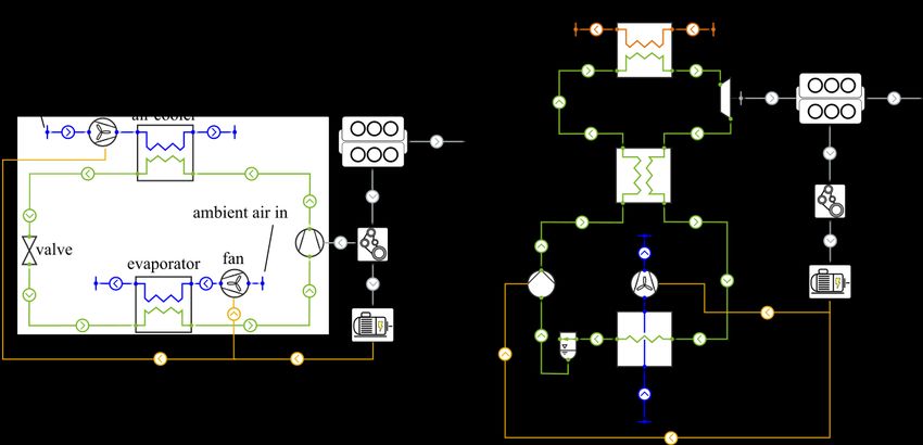
Paper ID: 35, Page 2

or ejector processes). The aim is to completely cover the energy need of the refrigeration system and
all its components. The focus within that research lays on system optimization with respect to dynamics
and environmental regulations. In this study, a preliminary comparison of two possible topologies for
combined waste heat refrigeration is carried out using a detailed simulation model of a long-haul
intercity bus equipped with an R-717-refrigeration system. The basis in this case is the classical Organic
Rankine Cycle and its derivative, the Organic Rankine Vapour Compression Cycle (ORVC). In terms
of the latter, the carried-out research is mainly distinguished to other researches (e.g. Yilmaz (2015),
Wang et al. (2011b), Saleh (2016 & 2018)) by using ammonia as working fluid/refrigerant.

               2. ORGANIC RANKINE (VAPOR COMPRESSION) CYCLE

Figure 1: Schematic overview of a conventional Rankine Cycle with internal heat exchanger. On the left hand
side, the diagram shows all essential components, the right hand side shows the corresponding thermodynamic
points of state for the working fluid cyclopentane.

Figure 2: Schematic overview of an Organic Rankine Vapor Compression Cycle. On the left hand side, the
diagram shows all essential components, the right hand side shows the corresponding thermodynamic points of
state for the working fluid ammonia.

Figure 1 shows the scheme of a conventional ORC with its components and corresponding
thermodynamic points of state. The system comprises of two main heat exchangers as sink and source,
an expansion machine and a pump. In order to increase the efficiency an internal heat exchanger (IHX)
is used as well. Depending on the system design, the sink can be another liquid flow, e.g. a cooling
circuit of the vehicle or ambient airflow. In addition, it is possible to install a separator after the
condenser on the working fluid side in order to assure that the pump is fed by saturated liquid only.
Figure 2 shows an example configuration of an Organic Rankine Vapor Compression Cycle (ORVC),
as commonly shown the literature (e.g. Yilmaz (2015), Wang et al. (2011b), Saleh (2016)). All relevant
components and thermodynamic points of state are depicted. The conventional refrigeration process,

          5th International Seminar on ORC Power Systems, September 9 - 11, 2019, Athens, Greece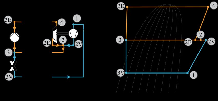
Paper ID: 35, Page 3
consisting of evaporator, condenser, compressor and expansion valve, is extended by a Rankine Cycle.
Thus, the presented process is a combination of a heat engine and refrigeration machine, sharing the
same working fluid. The remaining heat of both cycles is rejected via the same condenser on middle
pressure level. The expansion machine and the compressor are connected mechanically. Depending on
the system design, the expansion machine or the compressor can be connected additionally to an
auxiliary load or drive.
3. SIMULATION MODEL AND INVESTIGATED TOPOLOGIES
The used omnibus simulation model comprises all necessary subsystems and consumers of a long-haul
omnibus, such as the electrical system, drive-train, cooling system, passenger cabin, and the HVAC-
(Heating, Ventilation and Air Conditioning) unit. The modeling resolution is high and takes all relevant
dynamic effects into account. Furthermore, longitudinal dynamics have been considered. Vertical
dynamics have been neglected. The model was created by Kaiser (2019) using the object orientated
programming environment Modelica and has been validated with experimental data. All relevant
energetic interactions are considered and therefore the model allows to evaluate energetic measures
with respect to sub-system interactions such as implementing novel refrigeration systems or waste heat
recovery systems. The actual vehicle represents an omnibus with a passenger capacity of 48 people and
an engine peak power of 295 kW.
Table 1: Time average values of the evaluated reference system on a summer day in august on a journey from
Hanover to Munich.
Description Average value
Cooling load front- and roofbox evaporator 28 kW
Engine power 140 kW
Exhaust exergy flow at SCR-catalyst outlet 30 kW
The vehicle is originally equipped with an R-134a refrigeration cycle. In order to evaluate the impact
of topology design on system performance, the refrigerant is replaced by Ammonia (R-717) in form of
a drop-in. The gear ration between compressor and drive belt is changed in order to achieve the same
cooling power as in the original R-134a system. In that manner, in all three refrigerant cycles the same
refrigerant is used to make them comparable. Ammonia is here chosen as a place holder refrigerant,
because of its high volumetric cooling capacity and a good compromise in usability as a working fluid
in terms of waste heat activated cooling. In future work of the author, it is planned to use a novel
refrigerant, which has similar thermo-physical properties without the drawback of health and safety
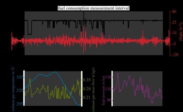
issues. Figure 3 on the left hand side shows the reference R-717-refrigeration system and its
connections into the powertrain of the omnibus. The refrigeration system has two evaporators in
parallel, one for the climatisation of the driver and one for the climatisation of the passenger
compartment. For the sake of simplification, only the main evaporator for the passenger compartment
is depicted, since it provides more than 90 % of the whole cooling load. The compressor is driven by
the drive belt of the combustion engine. All fans are fed by the vehicle’s electrical system, respectively
the alternator. Further explanation of the refrigeration system can be found in detail in Kaiser (2019).
Table 1 gives information about the evaluated reference system on a typical summer day in august on
a journey from Hanover to Munich.
In the following, the investigated topologies and their implementations into the omnibus are described.
All topologies have been created with the standard TIL- and TIL-Media library (Richter (2008), Gräber
et al. (2010), Schulze et al.(2011)) in Modelica. A detailed description with all dynamic modelling
approaches of the standard TIL and TIL-Media library can be found in Schulze (2013).
5th International Seminar on ORC Power Systems, September 9 - 11, 2019, Athens, Greece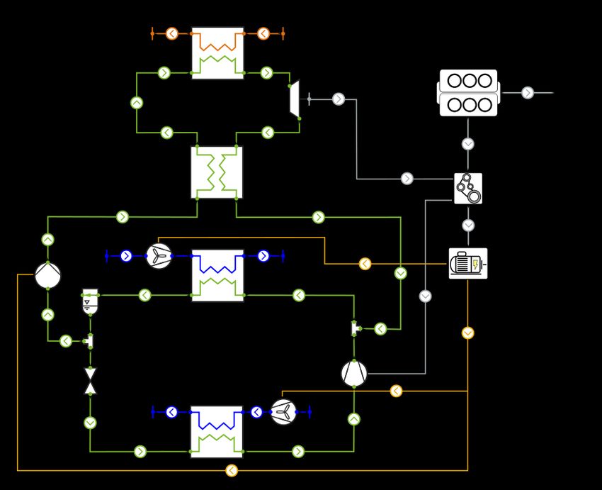
Paper ID: 35, Page 4

Figure 3: Schematic of the R-717 reference refrigeration system on the left hand side, and the ORC-topology on
the right hand side. Both systems are depicted including connections to engine, drive belt and generator. Orange
represents exhaust gas, blue represents air, green represents working fluid and yellow represents electrical
current. Mechanical work is depicted in gray.

Figure 3 on the right hand side shows the ORC-topology and its connections into the powertrain of the
omnibus. The expansion machine is coupled to the combustion engine with a transmission ratio of two,
i.e. the speed of the expansion machine is twice the speed of the engine. This is a result of an iterative
design process in order to achieve high pressures close to the pressure of maximum dew enthalpy.
Investigations by Ebeling (2019) have shown, that under full load the optimal high pressure is close to
that region. Fan and pump are fed by the vehicle’s electrical system, respectively by the alternator. The
working fluid is cyclopentane. In the literature it is quite often identified as one of the best performing
workingfluids in terms of mobile waste heat recovery, as for example in Ebeling (2019) and Reiche
(2018). Fan and expansion machine are assumed to have a constant overall efficiency of 70 %. The
interdependence of pressure increase and volume flow rate of the pump at nominal speed is modeled
by a quadratic function with the parameters pressure increase at zero flow rate and volume flow rate at
zero pressure increase. Furthermore, a parameter for nominal effective efficiency is used, which is set
to 55 %. The dependence of the aforementioned characteristic on rotational speed is modeled by affinity
laws. All heat exchanger models are based on physically motivated models with implemented
commonly used heat and pressure drop correlations (e.g. Haaf (1988), Shah (1979), Gnielinski (1975)).
The heat exchanger design has been carried out roughly with an expected amount of available space in
the vehicle. The evaporator is a Fin-And-Tube heat exchanger, the condenser is an Multi-Port-Extrusion
heat exchanger in a crossflow configuration. The internal heat exchanger is a plate heat exchanger.
For dynamic controlling the process two PI-Controllers are used. The first one sets the speed of the
pump and controls the inlet state of the expansion machine to 10 K superheated vapor. The second
controller sets the speed of the condenser fan and hereby the condensing pressure of the cycle. The
control variable in this case is the partial derivative of the exergetic efficiency with respect to the low
pressure level of the system. The setpoint is correspondingly zero, hence the exergetic efficiency is
maximized if the derivative gets zero. The partial derivative is calculated using a steady state model of
the system. The applied controlling technique has been introduced by Noeding (2019) as “zero-gradient-
control”.
Since the compressor of the refrigeration system is connected to the drive belt as well, the shown
configuration is similar to the one described in Wang et al. (2011a), where compressor and expansion
machine are directly coupled and the applied working fluid and refrigerant are R-245fa and R-134a. In
this work cyclopentane and R-717 are used. The author is not aware of any literature, that describes the
investigation of this combination of working fluid and refrigerant.

          5th International Seminar on ORC Power Systems, September 9 - 11, 2019, Athens, Greece
Paper ID: 35, Page 5
Figure 4: Schematic of the ORVC-topology including connections to engine, drive belt and alternator. Orange
represents exhaust gas, blue represents air, green represents working fluid and yellow represents electrical current.
Mechanical work is depicted in gray.
Figure 4 shows the ORVC-topology and its connections into the powertrain of the omnibus. This
topology is a combination of the vehicle’s reference refrigeration system and the described ORC-
topology. The condenser of the reference refrigeration system replaces the ORC-condenser. The
expected condensation heat is approximately twice the condensation heat of the reference refrigeration
system, hence the size of the condenser is doubled. The number of condenser fans is increased as well.
The chosen working fluid is again ammonia (R-717). The volume flow rate parameter of the pump is
adapted from cyclopentane to R-717 in order to match the increased evaporation enthalpy. The
expansion machine and the compressor are both coupled to the drive belt, the gear ratio between belt
drive and expansion machine is adapted so that similar pressure ratios as in the ORC-topology are
achieved. All other components and operating strategies of the system remain unchanged.
For controlling the outlet state of the expansion machine, a PI-Controller is used, which sets the speed
of the pump for controlling the outlet state of the expansion machine to 60 K superheated vapor. In that
manner, the following internal heat exchanger is provided with enough temperature difference to
transfer heat from mid pressure to high pressure level. The controls of the expansion valves, condenser
and evaporator fans are identical to the reference refrigeration system and remain the same as in the
model of Kaiser (2019).
The described topology is similar to Yilmaz (2015), where R-134a and R-245fa are investigated as
working fluid. In the system described by Yilmaz (2015), the compressor and expander are directly
coupled with no other external connection. However, in this work the expansion machine and
compressor are coupled via the drive belt of the vehicle. Hence, the shaft work of expander and
compressor may be unequal, so that power is drawn from or supplied to the engine. Furthermore, as
mentioned, in this work ammonia is used as working fluid.
4. BOUNDARY CONDITIONS AND SIMULATION RESULTS
4.1 Boundary conditions
In order to evaluate the integration of the presented topologies into the vehicle, a real driving scenario
from Hanover to Munich is applied as simulation input. The scenario considers vehicle speed, slope of
route and weather conditions. For the applied scenario a typical august summer day has been chosen,
further details are explained in Kaiser (2019). Figure 5 shows the vehicle speed and the corresponding
5th International Seminar on ORC Power Systems, September 9 - 11, 2019, Athens, GreecePaper ID: 35, Page 6
driving slope with respect to time as well as the system input boundary conditions and system response
of pressure at high pressure evaporator outlet for a representative time interval. In case of the ORC- and
ORVC-topology both systems are only activated during highway conditions. The fuel consumption
measurement interval has been chosen from 2000 until 23000 seconds of the journey. The mentioned
interval is depicted in Figure 5, as well. All topologies are compared within this period. In both
configurations, the ORC and the ORVC, the exhaust gas evaporator is integrated after the SCR-catalyst
of the exhaust after treatment system of the vehicle.
Figure 5: Real life driving scenario from Hanover to Munich (Kaiser, 2018). Vehicle speed and slope of route
depicted with respect to time (a). System input boundary conditions (b) and system response of pressure at high
pressure evaporator outlet (c) for a representative time interval of 3250 s to 3750 s for the ORVC-topology.
4.2 Results
Figure 6 shows the result for the exergy analysis in the mentioned driving scenario for the three
topologies. Exergy source and exergy demand are compared for each topology. The exergy balance is
formed around the engine, the drive belt and the gearbox, taking all necessary consumers into account.
The exergy demand is hereby divided into driving resistance and gearbox losses, engine auxiliaries (all
kinds of consumers like pumps or fans etc.), vehicle auxiliaries (lighting and electronic control units
etc.), HVAC auxiliaries (condenser and evaporator fans and control units), compressor shaft power and
the resulting drive belt losses. Electrical conversion losses of the electrical components are included as
exergy demand of the corresponding component. In case of ORC and ORVC applications, the exergy
demand of the pump and fan (only ORC) are depicted as well. As exergy source the corresponding
component is depicted in opposition and is divided into engine crankshaft and, if existing, expansion
machine.
It can be seen that the exergy demand covered by the engine decreases from the reference topology to
the ORC and ORVC topology. In case of the ORC topology, the exergy output of the engine decreases
by 4 % compared to the reference, in case of ORVC by 7.1 % compared to the reference. This decrease
corresponds to a fuel consumption decrease by 3.7 % and 6.5 % respectively. The reason for this
decrease is mainly due to the WHR system, since the expansion machine reduces the engine load, as
mentioned above. In case of the ORC, there is no direct impact on the refrigeration system itself. Both
topologies, reference and ORC, are using the same refrigeration cycle, hence there is no significant
change in power demand for refrigeration. On direct comparison of the ORC and the ORVC topology,
it can be seen, that the necessary work input of the compressor is decreased by around 4 kWh and the
work output of the expansion machine is increased by around 9 kWh. The ORVC condenser size is
increased, as well as the number of fans for condensation. This results in an increase of energy usage
of the HVAC utilities by around 1.5 kWh.
5th International Seminar on ORC Power Systems, September 9 - 11, 2019, Athens, GreecePaper ID: 35, Page 7
Figure 6: Exergy demand and source for the evaluated topologies with the for the period of a real life driving
cycle from Hanover to Munich between 2000 and 23000 seconds of the journey. The results show a primary
energy usage improvement between all topologies only in application of the described set of parameters.
The necessary work input for the pump is increased by 2.5 kWh as well. Still, the overall work input
for the WHR is lower in direct comparison to the ORC topology, since the expansion machine is able
to supply more energy and also there is no dedicated condenser fan needed. In case of the ORVC
toplogy, the engine has to provide 8 kWh of mechanical energy and in case of the ORC topology 22
kWh of mechanical energy in order to supply air conditioning for the passenger compartment.
Another aspect that can be seen from the simulation results is the impact of the expansion machine on
the drive train of the engine. As mentioned, in all three topologies identical boundary conditions were
applied. Due to that, the exergy demand for the driving resistance should be equal in all three
simulations. As shown in Figure 6, this is not the case. The exergy demand differs by about 13 kWh in
case of the ORC and by about 5 kWh in case of the ORVC topology compared to the reference. Because
of the thermal capacity of the WHR and the exhaust manifold, the time constant of the WHR is several
magnitudes bigger than that of the drivetrain’s mechanics, hence the expansion machine is still
providing energy while the driver is applying the brake pedal. Due to the additional power input of the
expansion machine into the drive train, the driver, represented by a PI-controller, tends to accelerate
and decelerate more aggressively, which leads to the shown increase in driving resistance, respectively
fuel consumption. Consequently, the fuel reduction potential for the shown ORC and ORVC
configuration is slightly higher than depicted in Figure 6. The adaption of the driver model as function
of drivetrain design is part of future work of the author.
5. CONCLUSIONS
The results show that with the applied parameters and model approach it is possible to effectively
decrease the fuel consumption of an intercity bus on a long-haul journey using both systems. In direct
comparison of the shown configurations with the applied set of parameters, the fuel reduction potential
of the ORVC topology is about twice of that of the ORC topology. Still, it has to be stressed, that in this
comparison two different approaches of condenser design has been applied. In case of the ORC
topology, it is assumed that the condenser is placed near the engine with little packaging space available.
In case of the ORVC, the original HVAC unit has been modified, which uses an condenser installed on
the roof of the vehicle, with obviously more space available. Also, it has not been taken into account
that the use of R-717 in direct evaporation systems can lead to grave safety issues, since it is a highly
toxic substance. Among others, the scope of future work is therefore to implement an ORVC with
alternative refrigerants which have no impact on the environment or vehicle passengers, similarly as
shown in Saleh (2018). It has to be evaluated, if yet a fuel reduction potential is given. In that case the
use of an ORVC would be highly promising, since the needed cooling load could be maintained with
simultaneously meeting environmental regulations, such as GWP and ODP. It then has to be evaluated,
if other topologies (e.g. absorption or ejector processes) can compete.
In summary, it has to be pointed out, that further extended research has to be carried out in order to
make the two systems more comparable. Several effects have not been analyzed, which could improve
5th International Seminar on ORC Power Systems, September 9 - 11, 2019, Athens, GreecePaper ID: 35, Page 8
the presented ORC configuration’s performance. Both, ORC and ORVC topology, have not been fully
optimized and will be presented in future publications.
ACKNOWLEDGEMENT
Parts of this publication have been developed with funding from the German Federal Ministry of
Education and Research (BMBF) within the research project VEOS – Verfahren zur energetischen
Optimierung dynamischer thermischer Systeme (KMU Innovativ, 01 | LY1502) and VEOTOP –
Verfahren zur optimalen Synthese und Topologieoptimierung komplexer thermischer Energiesysteme
(KMU Innovativ, 01 | LY1809B)
REFERENCES
Ebeling, P., approx. published in 2019, Konzeption eines Rankine-Prozesses für den transienten
Betrieb im Omnibus, PhD thesis, TU Braunschweig
Gräber, M., Kosowski, K., Richter, C., and Tegethoff, W., 2010, Modelling of heat pumps with an
object-oriented model library for thermodynamic systems, Mathematical and Computer
Modelling of Dynamical Systems, vol. 16, issue 3: p. 195–209.
Gnielinski, V., 1975, Neue Gleichungen für den Wärme- und den Stoffübergang in turbulent
durchströmten Rohren und Kanälen., In: Forschung im Ingenieurwesen - Engineering Research
vol. 41, Pt. 1, Springer-Verlag, 1975, p. 8 – 16.
Haaf, S., 1988, Wärmeübertragung in Luftkühlern., In: Steimle, F. (Publ..) ; Stephan, K. (Publ.):
Handbuch der Kältetechnik vol. 6, part B, Springer-Verlag, 1988. – ISBN 978–3–642–82523–1
Noeding, M., approx. published in 2019, Energieoptimierte Regelung von CO2-
Kompressionskältekreisläufen, PhD thesis, TU Braunschweig
Kaiser, C., approx. published in 2019, Untersuchungen zur Effizienz- und Leistungsverbesserung von
Omnibusklimaanalgen. PhD thesis, TU Braunschweig
Richter, C., 2008, Proposal of New Object-Oriented Equation-Based Model Libraries for
Thermodynamic Systems. PhD thesis, TU Braunschweig
Reiche, T., Galuppo, F., Espinosa, N., 2018, Waste Heat Recovery Potential on Heavy Duty
Long Haul Trucks – A Comparison, Proceedings of the 2nd ETA Conferencem Berlin: p. 141-
153
Saleh, B., 2016, Parametric and working fluid analysis of a combined organic Rankine-vapor
compression refrigeration system activated by low-grade thermal energy, Journal of Advanced
Research, vol. 7, issze 5: p. 651–660
Saleh, B., 2018, Energy and exergy analysis of an integrated organic Rankine cycle-vapor compression
refrigeration system, Applied Thermal Energy, vol. 141: p. 697-710
Shah, M. M., 1976, A New Correlation for Heat Transfer during Boiling Flow Through Pipes., In:
ASHRAE Transactions vol. 82, Pt. 2, American Society of Heating, Refrigerating and
Air-Conditioning Engineers - ASHRAE Inc., 1976.
Schulze, C., Gräber, M., Huhn, M., and Grätz, U., 2011, Real-Time Simulation of Vapour Compression
Cycles, Proceedings of the 8th International Modelica Conference, Dresden: p. 46 -55.
Schulze, C., 2019, A Contribution to Numerically Efficient Modelling of Thermodynamic Systems,
PhD thesis, TU Braunschweig
Wang, H., Peterson, R., Herron, T., 2011b, Design study of configurations on system COP for a
combined ORC (organic Rankine cycle) and VCC (vapor compression cycle), Energy, vol. 36,
issue 8: p. 4809-4820.
Wang, H., Peterson, R., Harada, K., Miller, E., Ingram-Goble, R., Fisher, L., Yih, J., Ward, C., 2011a,
Performance of a combined organic Rankine cycle and vapor compression cycle for heat
activated cooling, Energy, vol. 36, issue 1: p. 447-458
Yilmaz, A., 2015, Transcritical organic Rankine vapor compression refrigeration system for intercity
bus air-conditioning using engine exhaust heat, Energy, vol. 82, issue 82: p. 1047-1056.
5th International Seminar on ORC Power Systems, September 9 - 11, 2019, Athens, GreeceYou can also read