Experimental and Numerical Study of Spar Buoy-magnet/spring Oscillators Used as Wave Energy Absorbers

Page created by Zachary Zimmerman
 
CONTINUE READING
Experimental and Numerical Study of Spar Buoy-magnet/spring Oscillators Used as Wave Energy Absorbers
Proceedings of the Seventeenth
                   Sixteenth (2007)
                                (2007)
                                    International
                                       International
                                                  Offshore
                                                     Offshore
                                                           andand
                                                               Polar
                                                                  Polar
                                                                     Engineering
                                                                        Engineering
                                                                                 Conference
                                                                                    Conference
Lisbon, Portugal, July 1-6, 2007
Copyright © 2007 by The International Society of Offshore and Polar Engineers(ISOPE)
ISBN 978-1-880653-68-5; ISBN 1-880653-68-0(Set); ISSN 1098-6189 (Set)

      Experimental and Numerical Study of Spar Buoy-magnet/spring Oscillators Used as Wave Energy
                                                                     Absorbers
                                                                                                                                

                          Annette R. Grilli , Jon Merrill , Stéphan T. Grilli , Malcolm L. Spaulding , and Jeffrey T. Cheung
                                   1. Department of Ocean Engineering, University of Rhode Island, Narragansett, RI, USA
                                               2. Teledyne Scientific and Imaging, Thousand Oaks, CA, USA

ABSTRACT
                                                                                 KEYWORDS : Wave energy systems; heaving buoy; linear
     We study free-floating point absorption wave generators, con-               energy generator; floating body dynamic; Boundary Integral
sisting of an assemblage of one or a few (mostly heaving) spar                   Equations; linear waves.
buoys, housing at least one short-stroke linear generator (SSLG),
made of a magnet, suspended to a spring, and oscillating within a                INTRODUCTION
coil. This system is aimed at producing low and renewable wave
                   

power (up to         kW) for marine coastal surveillance systems.
                                                                                      Our goal is to develop a system to produce low amounts of
Both scale model experiments and numerical modeling are per-                                  

                                                                                 power (        kW) for marine surveillance instrumentation (e.g.,
formed in order to tune the system’s parameters and maximize
                                                                                 autonomous target recognition instruments, persistence and ubiq-
its response for a target sea-state (i.e., operate near resonance in
                                                                                 uitous sensor systems, tracking and identification of maritime ves-
heave and magnet motion). We find that, for such buoy systems,
                                                                                 sels, and miniature underwater sensor networks), based on captur-
viscous friction is the dominant damping mechanism near reso-
                                                                                 ing renewable wave energy. To do so, we design and optimize a
nance and, hence, the buoy’s wet extremities must also be prop-
                                                                                 new type of freely floating, slackly moored buoy, housing a “Short
erly streamlined, and rolling must be minimized as it may sig-
                                                                                 Stroke Linear Generator” (SSLG), made of spring, magnet, and
nificantly increase such damping. This can be achieved with a
                                                                                 coil components. The response to periodic and irregular wave
so-called trispar system, in which 3 spars buoys of identical di-
                                                                                 forcing, of the double oscillator constituting the buoy-SSLG sys-
ameter are mounted in an equilateral triangle configuration, one
                                                                                 tem, is analyzed using both state-of-the-art numerical models and
diameter apart from each other. Since the heave resonance period
                                                                                 scale model testing in a laboratory wave tank.
of a spar buoy is primarily a function of its draft, to lower this pe-
riod and better match the resonance period of the SSLG, the draft                     Our system falls within the general category of independent
of each buoy in the trispar is varied (in the scale model, to 25, 50             oscillators, point absorbers (Stallard et al, 2005). [A review of
and 100 cm), with the longest spar buoy housing the SSLG, while                  various forms of ocean wave energy systems can be found in,
simultaneously adjusting their dead weight.                                      e.g., Previsic et al (2004).] The key features inherent in this type
                                                                                 of design include response to omni-directional wave forcing,
     Experimental results in periodic waves, well supported by                   direct conversion from mechanical energy of the buoy motion to
numerical modeling, show a significantly improved performance                    electrical energy, thus eliminating the need for an intermediate
of the trispar vs. single spar design, both with respect to parasitic            component in the power take off system (e.g. turbine), no external
roll oscillations (almost none observed for the tripar) and power                working parts, and minimizing the number of moving parts and
gene- ration. The good performance of the trispar, particularly                  complexity of the structure and system. Budal and Falnes (1975),
in terms of “Capture Width Ratio”, is confirmed by preliminary                   French (1979), and French and Bracewell (1995), have concluded
                                                                                 that the most promising and economical form of these types of
numerical simulations in irregular waves. Future work will
                                                                                 systems are those that can be tuned to the frequency of the waves
test the trispar in irregular waves and explore dynamic tuning                   present in the ocean and hence take advantage of the increased
strategies (e.g., latching) of the SSLG, in order to further improve             amplitude of motion at the natural heave frequency of the system.
power generation.                                                                Given the low power applications that are targeted, the desire

                                                                            1

                                                                           489
Experimental and Numerical Study of Spar Buoy-magnet/spring Oscillators Used as Wave Energy Absorbers
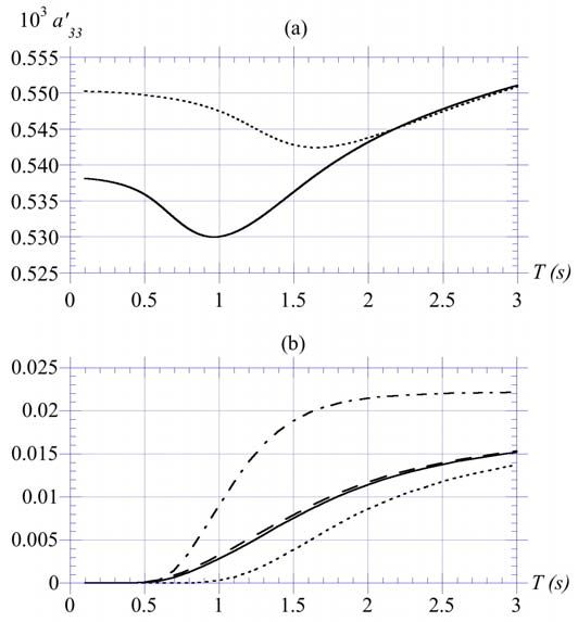
to have the physical size of the system limited so that it can be             one fixed frequency. Systems can be tuned to improve their re-
routinely deployed and retrieved from either a surface vessel or              sponse by fixed, slow, and fast tuning. Fixed tuning refers to prop-
even helicopter, and to keep the construction and maintenance                 erties of the device (size, shape, and mass), that are established in
costs as low as possible, a simple spar buoy design (both single-             the basic design and hence not readily changed once the buoy is
and multiple-spars) was pursued.                                              constructed and deployed. Slow tuning refers to changes in the
                                                                              response on time scales of minutes to hours and typically is fo-
                           (a)                         (b)                    cused on changing the systems buoyancy and hence its mass and
                                                                              effective stiffness. This can be achieved by active ballast control.
                                                                              Fast tuning actively controls system dynamics on time scales of
                                                                              variations of individual waves or wave groups. The latter tuning
                                                                              is typically very difficult to implement because device character-
                                                                              istics must be changed quickly enough to alter its response. Also,
                                                                              for typical irregular sea states, one cannot exactly predict waves
                                                                              that are about to reach the system (and thus dynamically tune it
                                                                              for such waves), and hence one can only make a forecast and iter-
                                                                              atively correct it over a number of wave periods (e.g., Babarit and
                                                                              Clément, 2006). In this initial work, we only explore fixed tuning
                                                                              of the system.

                                                                              THE ANALYTICAL AND NUMERICAL MODELS

                                                                              Dynamic of the heaving spar buoy
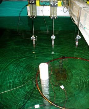
Fig. 1 : (a) Spar buoy model SB3 in twave tank (      m,  
                                        

  m), forced by     cm and     s waves. Capacitance                         We consider a rigid spar buoy of cylindical shape, with draft
wave gauges, buoy containment rink, and SSLG output wires are                  , external diameter , and length (Fig. 1a), floating in water of
shown. (b) SSLG undergoing dry testing.                                       specific mass and depth . The submerged extremity of the buoy
                                                                              is streamlined to reduce friction drag generated during motion,
     Three major, linked subsystems, are considered in the design:            but this slight change of geometry is neglected in the following
(i) buoy dynamics, i.e., mechanical buoy response to wave forcing;            idealized analysis. For slender spar buoys, the heave natural  fre-
                                                                                                                                                
(ii) generator mechanical dynamics, i.e., response of the SSLG                quency can be predicted by the simplified equation,               
resulting from the movements of the buoy (motion of magnet rel-               (Berteaux, 1994). Using the numerical model     detailed  below,  we
                                                                                                                          
ative to the coils); and (iii) generator electric dynamics, i.e., de-         verified that this equation is accurate for       .
                                                                                                                                                                                                  

termining the electrical power output from the linear generator,
                                                                                    In transient waves, the buoy heaving motion in the time do-
given the dynamics of the armature-stator system. In the most                                                                

                                                                              main, denoted here by  , under the action of inertia, radiative
general case, there are feedbacks between the various components
                                                                              wave damping, viscous damping, gravity, and buoyancy forces, is
of the system, that must be considered to optimize its overall per-
                                                                              governed by the 2nd-order nonlinear Ordinary Differential Equa-
formance. As an example, the movement of the armature will
                                                                              tion (ODE),
result in a change of the weight distribution and hence impact the
buoys movement. Similarly the electro-magnetic force from the                                                                                            ! 
armature-stator system will alter the mechanical response of the                                                                                              
                                                                                                                                          
generator. In the present study, the focus has been restricted to
the buoy and mechanical SSLG dynamics portion of the problem                                   " #         $     #               $               %                                    ' ( ) * +
                                                                                                                                                                           &                               (1)
(systems (i) and (ii)). In the experimental part of this work, the
heaving buoy(s) are equipped with a SSLG model, built by Tele-                                                                                                                     
dyne Scientific and Imaging, LLC (TSI), in which a new type of                where the upper dots denote time derivatives,        , is the buoy
                                                                                                                                                                                                 

friction reduction ferrofluid is used, as a fluid cushion between the         mass (with ,  - .  , the buoy displacement),          the instan-
moving magnet and the coil. Hence, magnet damping due to fric-                taneous heave added mass (i.e., for a very large frequency),
tion becomes negligible as compared to mechanical damping due                       "
                                                                                            

to electro-magnetic interactions between the magnet and the coil.                          /    - . 0 1                                                                                                       (2)
     Power production can be maximized by tuning the response
of subsystems (i) and (ii) to wave forcing. The goal is to select             is the viscous damping
                                                                                               3        coefficient, with 0 1 the drag% coefficient
                                                                                                                                                
                                                                                                                                        
parameters so that the mechanical responses of the buoy and the               and - .  2         the horizontal$ buoy cross-section,            - .

SSLG are near resonance for the most prevalent wave conditions.               is the buoyancy restoring term, is the wave vertical particle ve-
                                                                                                                                        

Ideally, in accordance with typical ocean wave energy spectra, the            locity (defined later), and &      is the heave wave excitation force.
system should have broadband response so that it optimizes wave               The bracketed term in the right-hand-side is a feedback coupling
energy capture over a range of wave frequencies, and not just at              force due to the spring/magnet oscillator motion, which will be
                                                                              discussed later.

                                                                        490
Experimental and Numerical Study of Spar Buoy-magnet/spring Oscillators Used as Wave Energy Absorbers
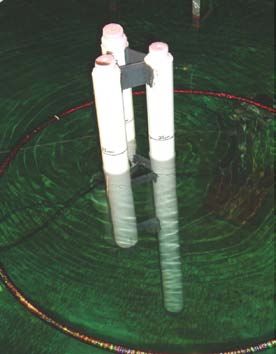
The integral in Eq. (1) represents a memory term (e.g.,                                                                                                                                                 given by Eq. (5). [Note, the second term is kept in Eq. (6) to have
                                                                                                            

Babarit et al., 2006), in which      , the heave impulse response                                                                                                                                           the same damping outside of the resonant frequency band, where
                                
function, can be calculated as a function of the buoy frequency                                                                                                                                             viscous damping vanishes, as in the linear periodic case detailed
response by either of the inverse Fourier transforms (Lee, 1995),                                                                                                                                           below.] For linear periodic waves, we also have,
                                                /                                                                                                                                                                                                  
                                                                                                                                      !                                                                                                                                                                
                                                                                                                                                                                                                    $                                                                                                                                       
                                                                                                                                                                                                                                                                                                                                                                          

                                               2                                                                                                                                                                                                                                                                                                                                   (7)
                                                /
                                                                   "                                    !
                                                                                                                                                                                         (3)                                                                                    
                                               2                                                                                                                                                          with the wavenumber        given, for each wave component, by the
                                                                                         "                
                                                                                                                                                                                                            linear dispersion relationship,
as a function of          and         , the frequency dependent
heave added mass and wave radiative damping terms, respectively.                                                                                                                                                                                                                           

                                                                                                                                                                                                                                                                                                                                                                                         (8)
    Assuming superposition of linear periodic waves, for any
                                                                                                                                                                                                                                                                                                                                                                          
given sea-state represented by a wave energy density spectrum                                                                                                                                               which simplifies to               for deep water waves (      2 ).
     

-    (e.g., Pierson-Moskowitz (PM) or JONSWAP (JS)), the time                                                                                                                                               Eqs. (5) to (8) are implemented as a MATLAB program that di-
dependent free surface elevation can be expressed as,                                                                                                                                                       rectly reads WAMIT outputs. After being transformed into a sys-
                                                                                                                                                                                                           tem of two 1st-order ODEs by change of variables, the nonlinear
                                      
                                                                                                    
                                                                                                                                                                                                            2nd-order ODE (6) is time integrated by a Runge-Kutta method,
                                                                                                                                                                                        (4)
                                                                                                                                                                                                            using a standard MATLAB function. Initial conditions are simply
                                                                                                                                                                                                                                    
                                                                                                                                                                                                            set to      for   . Computations      are usually pursued
                                                                                                                                                                        '       /   +                                                                /               
where, for a specified set of random phases               2 , the                                                                                                                                          up to at least     , with   2               the peak spectral
amplitude  of each harmonic wave component of frequency                                                                                                                                                    period. If the buoy is subjected to periodic waves only, the same
   can be obtained by inverse Fourier transform of the spectrum.                                                                                                                                            WAMIT-MATLAB (WM) model is applied, from an initial state                
Accordingly, the wave heave excitation force can be calculated as,                                                                                                                                          of rest, assuming   , until the transient buoy motion reaches
                                                                                                                                                                                                           a periodic state.
                                                                                                                             
          &


                                                                                                                                                                                          (5)                    In the periodic case, linearized equations governing the buoy
                                                                                                                                                                                                            motion for 6 degrees of freedom (dof) can be expressed in com-
                                                                                                                                                                              
                                                                                                                                                                                                            plex form (e.g., Newman, 1977); for the heave dof, we have,
where, for each of  wave components,                                  are                                                                                                                                                         
                                                                                                                                                                                                                                                                                              "  %                                                 ! " #
the module and phase, respectively of the heave exciting force                                                                                                                                                                                                                                                                                                                           (9)
caused on the buoy by a periodic wave of unit amplitude and fre-
                                                                                                                                                                                                                                                                                    
quency      (including diffraction effects).                                                                                                                                                                with            ,  $      , a wave of amplitude  and frequency
                                               "                                                                                                                       
                                                                                                                                                                                                                      
     The frequency dependent coefficients                        , in the                                                                                                                                    , and     the complex amplitude of he buoy heave motion. A
above equations, are calculated using the standard Boundary El-                                                                                                                                             frequency dependent Response Amplitude        Operator (RAO) can
                                                                                                                                                                                                                                                       #  #
                                                                                                                                                                                                                                                   
ement code WAMIT (Lee, 1995; Newman, 1977), in which lin-                                                                                                                                                   be defined for each dof; for heave: %             . Solving Eq. (9)

ear free surface boundary conditions are assumed. Specifically,                                                                                                                                             yields, for a spar buoy in simple heaving motion,
once specified the buoy geometry and mass distribution, compu-
                                                                                                                                                                                                                                                                                                                                                                                       *
tations are performed  with WAMIT, for  equally spaced periods                                                                                                                                                                                                & %                             
                                                                                                                                                                                                                                                                                                                                                    
                                                                                                                                                                                                                                                                                                                                                                      
                                                                                                                                                                                                                                                                                                                                                                            "   ' ( )
                  /                                                                                                                                                                                              %                                                                                                                                                                    (10)
   (with         2  ), in the specified interval   
                                                  
                                                                    .
                                                                                                                                                     

WAMIT’s procedure F2T can also provide              , by calculating
                                                                                                                                                                                                                                                                                                                                        "          

the integrals in Eq. (3), if required.                                                                                                                                                                      Maximum heave response %                                                                                                                           occurs if,
                                                                                                                                                                                

     As we shall see, for slender spar buoys with             ,                                                                                                                                                                                                %
is small and varies very little over any useful frequency interval  "                                                                                                                                                             +                                                                                                                                             (11)
including the buoy heave resonance frequency           , while          is
very small, reflecting the fact that such buoys generate very little                                                                                                                                                                   ,            
                                                                                                                                                                     
                                                                                                                                                                                                            With                for a slender spar buoy, Eq. (11) yields
waves in heaving motion. Thus, Eqs. (3) yields                      , and
hence the memory term in Eq. (1) is negligible, particularly as                                                                                                                                                         , the heave natural frequency defined above. In " the
                                                                                                                                                                                                                                      
                                                                                                                                                                                                                                                                             
compared to the viscous damping term. Accordingly, the ODE                                                                                                                                                  absence of viscous damping and with a very small value for          ,
governing the transient heaving motion of a slender spar buoy can                                                                                                                                           it can be shown that the maximum heave response predicted
be simplified to,                                                                                                                                                                                           near the resonance frequency using Eq. (10) (such as done in
                                                                                                                                                                                                            WAMIT), is overestimated by a factor of 10-20 in most cases, as
               "       " #  $ #  $                                                                             %                                      ' ( ) * +
                                                                                                                                                        &                           (6)               compared to laboratory measurements. When solving Eqs. (6)
                                                                                                                                                                                                            to (8), and properly calibrating the drag coefficient 0 1 , however,
                                                                                    "            

with                     ,(            the heave added mass and                                                                                                                                            predictions of the WM model agree very well with measurements,
radiative damping at the dominant frequency of the sea state, re-                                                                                                                                           even near the natural resonance frequency.
                                                                                                                                                                                             

spectively (typically, the peak spectral frequency ), and &

                                                                                                                                                                                                      491
Experimental and Numerical Study of Spar Buoy-magnet/spring Oscillators Used as Wave Energy Absorbers
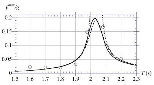
Dynamic of the spring-magnet oscillator                                                                                              of Eqs. (1) and (6) (the bracketed term). This force is quite small
                                                                                                                                     for typical spring constants used in the SSLG, as compared to the
     Similar to the spar buoy, a 2nd-order linear ODE is derived to                                                                  other forces in the equation. However, its effect on the buoy dy-
                                                              *                                                          

describe the motion of the spring-magnet system, denoted by       ,                                                                  namics may become significant for large amplitude motions near
that is at the core of the SSLG. Assuming a magnet suspended                                                                         resonance, as we shall see in the application section below.
by a single spring, this equation has mass, linear damping, and                                                                           Finally, one can calculate the mechanical power extracted
spring restoring terms in the left-hand-side, and is forced in the                                                                   from the magnet motion, corresponding to the magnet damping
                                                                                                                                             *                           *
                                                                                                                                                                                            
right hand side by the inertia force induced on the spring-magnet                                                                    force      in Eq. (12), as           . Coefficient , which here
system by the buoy heaving motion,                                                                                                   is a specified parameter, should in fact be derived from the emf
       ) *                  *                  ( ) *                     )                                                     force generated between the coil, built around the generator, and
                                                                                                                     (12)          the magnet, due to their electro-magnetic interactions, as a func-
       )                                                                                                                            tion of the magnet strength and coil circuit characteristics. This
with        the spring-magnet mass, the damping coefficient and                                                                      electro-magnetic part was not modeled in this work and, in the
( )
     the spring stiffness. (If the magnet
                                     (
                                             is suspended (in) between
                                                                  (                                                                 applications, the damping coefficient is simply adjusted in order
two
(
     springs   of stifnesses    and     , we  simply have                              
                                                                                                                                     to yield   values in agreement with those measured    in wavetank
                                                                                                                                                                                       ) )
  
    . If, at static equilibrium of the SSLG, the springs have initial                                                                tests of the generator. We further define               and use the
                                                                                                                                                                      
lengths  and  from their non-deformed state, we have,
                               
                                                                                                                                     non-dimensional coefficient in applications.
       )                 (                    (


                                                                                                                      (13)          APPLICATIONS

when spring 2 is located  above spring 1. If only spring 2 is used,                                                                       Laboratory experiments and numerical simulations are per-
         )      )  ( )
we find                  for the initial (static) extension of the                                                                 formed to design a spar buoy-based system, equipped with a
spring.                                                                                                                              SSLG, to capture renewable wave energy. The prototype sys-
                               *            *          
    Solving Eq. (12), with                  at      , for a                                                                 tem performance      is to be optimized for shelf wave conditions, i.e.,
                                    )                                                                                                    3                                                                   
harmonic forcing of amplitude          .  and frequency  on the                                                                             s. For a single spar buoy, assuming                     , this leads
                                                          #* #
right-hand-side, we find the spring-magnet RAO                as,                                                                 to a prototype draft of    m and, to satisfy the slender spar
                                                                                                                                     buoy requirement, a buoy exterior diameter                               m. Scale
                                                                                                        *                            model experiments were performed in the wavetank of the Uni-
                       )             & ( )                          
                                                                             )    
                                                                                              
                                                                                                    ' ( )
                             .                                                                                       (14)          versity of Rhode Island, Department of Ocean Engineering (30 m
                                                                                                                                     long, 1.8 m deep and 3.6 m wide), which is equipped with a flap
                                                                                                                                                                                                        '      /    +
                                                                                                                                  wavemaker operating in the periods range                                  s. Peri-
As  for the buoy, we find that maximum response 
 ) 
                                                                                                                                                                                 '                  +
                      
                                                                                                                                     odic waves, with amplitude                            m were generated
     .      occurs at the natural frequency of the system,                                                                                                         

                                                                                                                                     in water of depth    m. Based on linear theory, this created
                                                                                                                                                                              
                           ( )                                                                                                      deep water waves for                  s and intermediate water depth
                                                                             )                                                                     

                     +  )                       +        )                                                         (15)          waves for               s.
                                                                                                                                                                                   

                                                                                                                                          A geometric scale of                       was selected and a series of

which, for a single spring, only depends on the spring static ex-                                                                    cylindrical spar buoy models were initially built and tested,                    
                                                                                                                                                                                                                        with3
tension; in particular, the longer the SSLG, the lower           its natural                                                         draft      m, length     to 0.7 m, and diameter                            
                                   )                        ) 
frequency. In practice, having               requires         , and hav-                                                         or 0.06 m (e.g., Fig. 1a). To reduce the viscous drag coefficient
ing these frequencies matching the peak spectral wave frequency                                                                      0 1 and maximize heaving motion, each buoy submerged end was
  
    , while keeping the spar buoy within a reasonable size, may be                                                                   equipped with a streamlined nose cap. These initial buoy mod-
difficult, particularly considering that, due to magnet motion, the                                                                  els were constructed without a SSLG installed within them, but
total length of the SSLG that must fit within the buoy length is                                                                     they had an equivalent distribution of mass and, hence, location
                      / )                         
                                                                                                                                     of the center of mass, as the planned prototype. Subsequent buoy
typically closer to  . For instance, for    s (correspond-
                                                    )                                                       

ing to a typical swell peak), we find        m, which                                                                         models were built and tested with an internal SSLG (Figs. 1a,b).
makes the buoy prohibitively long. For typical         shelf wave condi-                                                             All models were equipped with high precision, remotely operated,
                                                   3
tions inNew England, however, we have                   s, which yields                                                          three-axis micro-accelerometers           (Micro Strain 900/868 MHz G-
       )                                                                                                                                                /
          m, which may be achievable with a buoy of, say, total                                                                  link wireless;         range; 25 mm x 39 mm x 7.3 mm dimensions).
length   m or so.                                                                                                                  Based on their draft,     the initial buoy models              had a natural heave
                                                                                                                                                         3 3                                3 /         

                                                                                                                                     frequency                 r/s or                       s, which corresponds
      After transforming Eq. (12) in a system of two 1st-order
                                                                                                                                     to the prototype natural frequency, when applying a $ Froude
ODEs by change of variables, the system of 4 first-order ODEs
                                                                                                                                     scaling (e.g., White, 1999).
resulting from Eqs. (6) and (12) is time integrated, using the stan-
dard MATLAB function mentioned before, to simulataneously                                                                                 A first series of experiments were run that verified the near in-
                  * 


provide        and       . In this coupled ODE system, due to its                                                                   dependence of the heave RAO, %                       , on , in the period range
motion, the SSLG creates a feedback reaction force onto the buoy                                                                          to 2.5 s. The independence of heave characteristics to
                                     ( ) *
casing, that is represented by a           force in the right-hand-side                                                              buoy diameter was also verified by applying the numerical mod-

                                                                                                                               492
Experimental and Numerical Study of Spar Buoy-magnet/spring Oscillators Used as Wave Energy Absorbers
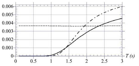
els, in both the standard WAMIT linear and the WM nonlinear,                            signed and built a so-called “trispar” buoy model, made up of 3
                                                                                                                                                   /
modes (the latter after calibrating the drag coefficient using exper-                   spar buoys of diameter            m, draft      m, 0.50 m
                                                                                                                                                                            

iments). Experiments also showed that parasitic roll oscillations                       and 1.0 m, respectively, and total mass                 kg, mounted
were excited for       m in all the buoys, in part because of                     on an equilateral triangle arrangement (Fig. 2). To minimize the
the proximity of the natural roll and heave periods for these buoys.                    interference of the heave flow around each spar and keep the sep-
Rolling led to increased viscous damping of the buoy heaving mo-                        aration length of individual spars small compared to the forcing
tion, which greatly reduced the heave RAO near resonance. Verti-                        wavelength, the separation of the spars was set to . The longer
cal fins were mounted on a buoy in order to limit roll oscillations,                    buoy in the trispar is identical to SB3 and can accommodate an
but this method met with limited success. A different system,                           internal SSLG. Each of the three spars has a different heave natu-
                                                                                                                                  

made of multiple spar buoys, was developed to better separate the                       ral period (   s, 1.4 s, and 2 s), covering the range of wave
heave and roll natural frequencies, and reduce roll oscillations;                       forcing in the tank. We will show that the trispar resonance    
                                                                                                                                                             pe-                                     

this is detailed later.                                                                 riod occurs near the average of the three buoys’, at               s,
                                                                                                                           )                        
                           (a)                        (b)                               which is much closer to both  and the targeted  . Hence, as
                                                                                        expected, we shall see that both the trispar heave RAO and SSLG
                                                                                        power generation are greatly improved, as compared to SB3.

                                                                                                                                                                                      /         
                                                                                        Fig. 3 : WAMIT
                                                                                                  "  
                                                                                                            results for SB3 buoy : (—)  ; (- - -)                                                      ; (—
                                                                                        - —)           .
Fig. 2 : (a) Trispar buoy undergoing tests in the wave tank at reso-
nant conditions (the vertical displacement of the spar far exceeds
the amplitude of wave forcing); (b) Dry trispar.
                                                                       )
      A SSLG oscillators of mass 0.865 kg, including                         
  /
    kg for the spring and magnet mass, was built by TSI, and
installed in a cylindrical   )
                                casing
                                    3 3 of total) length3 0.99 m (Fig. 1b).
                                                     

A natural frequency                    r/s (         s) was measured
in both dry benchmark tests (Fig. 1b), and wavetank experi-
ments of  3 the generator.     3With this data, Eqs. (13) and (15) yield
  )                    ( )      

        m and               N/m. In the dry benchmark tests, the
SSLG motion was forced in both amplitude (1.5 to 6 cm) and pe-
riod (0.5 to 2 s), using a variable speed DC electric motor, and its                    Fig. 4 : Maximum dimensionless heave acceleration for SB3,
power output was measured for one coil, using a rectifying circuit                                                

                                                                                        with   3     m: experiments (  ); uncoupled WM results with
with varying resistance load. It was determined that, in the range                      0 1    (- — -); coupled WM results with 0 1      (—);
of parameters tested, which simulates anticipated wave conditions                                                           

                                                                                        linear solution       % , from Eq. (10) (- - -).
in the tank, maximum power output (0.2-0.3 W for 1.5 cm ampli-
                                  )
tude at resonance period  ) occurred for a 100 load, the load                                The power production of various energy systems can be com-
that was later used in tank tests.                                                      pared by calculating their Capture Width Ratio (Hagerman and
      To accommodate the SSLG size, a longer and wider spar buoy                        Bedard,
                                                                                                 2003), defined for a width  of the system, as CWR 
                                                                       /                                
than used before, referred to as SB3, was built with :    m,                                  with, for a periodic waves,
                                        / /
          m,       m,              kg (Fig. 1a). Due to its deeper                                                                            %                        / 
                                                                         /                                   
                                                                                                                      
draft, however, SB3 is resonant at                     r/s (        s),                                                       %       %           &                            '
                                                                                                           /                            ;           /                 /                        (16)
which leads to a significant mismatch with both the target sea-state
        )
and        and, hence, a low power generation with the SSLG.
                                                                                        the period-averaged
                                                                                                                power (in W/m) and group velocity, respec-
                                                                                                %                                      
      In an effort
               )
                    to shift the heave resonance peak to lower periods,                 tively (              the phase velocity, with given by Eq. (8) as
closer to  , and broaden the spectral response of the buoy (while                      a function of  and ) and   the time-averaged output power
                                                                                                             /
reducing spurious roll oscillations, as mentioned before), we de-                       (equal to          for a harmonic spring motion).

                                                                                  493
/
     Details of experiments and WM simulations for SB3 and the                              tions for                    s. When running the model in coupled
trispar buoys are given in the following.                                                   mode, the buoy motion is slightly amplified near resonance by
                                                                                            the SSLG oscillations and a good fit is obtained by using a larger
                                                                                            value of 0 1     . This value is more consistent with earlier tests
                                                                                            of SB3 without the SSLG (not shown here), for which we found
                                                                                            0 1      , and with the literature. [The Reynolds number based
                                                                                                                                                       

                                                                                            on buoy draft would be about                             near resonance, which
                                                                                            is in the turbulent regime. Experiments performed for buoys with
                                                                                            smaller draft (and diameters) led to larger 0 1 values, which is con-
                                                                                            sistent with the corresponding decrease in Reynolds number (e.g.,
                                                                                            White, 1999).] Heave resonance occurs in the coupled simulations
                                                                                                                                      /    /                                     /
                                                                                            for a slightly lower                         s, which is close to               s.
                                                                                            The simulated values of maximum buoy acceleration (both uncou-
                                                                                            pled and coupled) agree very well with the linear analytic solution
                                                                                                                                                                           

                                                                                            from Eq. (10), outside of a narrow period range                                  to
                                                                                            2.15 s, near  . This confirms that nonlinear viscous damping is
                                                                                            negligible for small buoy motion but is dominant near resonance.
                                                                                                                                                           
                                                                                                  Fig. 5a shows the buoy heave RAO ( % ) and corresponding
                                                                                            spring-magnet RAO (  ), predicted in the WM simulations, both
                                                                                            uncoupled and coupled, as a function of the forcing period (case
                                                                                                                                                                          
                                                                                            of Fig. 4). Different values of the damping parameter                             
                                                                                            to 4 were tested and, as expected, the SSLG response greatly de-
                                                                                                                                                                /
                                                                                            creased with . Fig. 5a shows results for                               , which gives
                                                                                            a reasonable fit for the predicted maximum power output of the
                                                                                            SSLG in Fig. 5b, and compares these to the linear analytic so-
                                                                                                             
                                                                                            lution, for % , Eq. (10) (note, the buoy heaving motion is only
Fig. 5 : Simulation of SB3-SSLG system response (Figs. 3, 4
                                                                                           affected by that of the SSLG in the coupled simulations), and that
case). (a) Heave ( % ) and spring (  ) RAOs: coupled (—), un-
                                                                                            based on the predicted maximum         
                                                                                                                                                buoy acceleration,
                                                                                                                                                                  for  (i.e.,
coupled model (- —-); linear solution (- - -) (Eqs. (10) and (14)).                                                                                    

                 /                                                                      applying Eq. (14) with .                                     in the coupled WM
(b)       for         in : experiments (  ) (W); coupled WM
                                                                                            model). We see that the nonlinear and linear results agree very
simulations (—) (W); as the CWR for the latter (- - -).                                                  
                                                                                            well for % , outside of the resonant period range mentioned ear-
                                                                                            lier and, as expected, for  , both coupled WM and corresponding
Spar Buoy SB3 with SSLG in periodic waves
                                                                                            linear results agree very well for all periods, since the SSLG is
                                                                                            a linear oscillator. The               maximum magnet motion amplitude at
       Buoy SB3, equipped with the SSLG system, was tested in                                                  *    3
the wavetank, for periodic waves of amplitudes       to
                                                                             
                                                                                            resonance is                           , or 7 cm, while the maximum heave


0.06 m, and depth    m (Fig. 1). In each case, both buoy                                 amplitude is                        or 0.2 m.

heave acceleration and SSLG power output were measured, to-                                       Fig. 5b shows coupled simulations of the maximum power
gether with forcing wave characteristics. To compare measure-                               generated by the SSLG, as a function of the forcing period, for
                                                                                                  /
ments with simulations, WAMIT was first run for many periods                                        . A few maximum output powers, measured in laboratory
                                                                     

(typically    ), equally spaced between     and 3 s.                                 tests with the 100 circuit, are also shown on the figure. We see,
                                                                                                                
Figure     3 shows the calculated dimensionless               heave, added mass             the selected value gives a reasonable fit of these to simulations.
                                   "     " 
                                                            

                  , radiative   damping                        , and wave forc-          Maximum predicted power at resonance is a modest 0.07 W. Fi-


ingmodule  "                   . For all periods,                  (   %         nally, Fig. 5b shows the CWR, defined in Eq. (16), simulated as a
                            

of ) while     ( , hence confirming that, for a slender                                function of wave period for                           . A maximum value of 18%
                    

spar buoy,                    in Eqs. (1) and (3). We also see that very                   is reached at resonance, but the CWR becomes less than 5%, out-
                                                                                                                                                            
                                           
                                                                                            side of a 0.14 s wide period range from      -2.1 s. Hence,
little wave forcing        occurs for   s.
       Fig. 4 compares maximum heave accelerations measured for                             the SB3-SSLG system is moderately efficient at capturing energy
SB3, as a function of wave period for       m, to those
                                                                 
                                                                                            from periodic waves very near its natural heave period.
simulated with the WM model, using parameter values shown in
                                                                                            Trispar Buoy with SSLG in periodic waves
Fig. 3. When running the model in uncoupled mode (i.e., neglect-
ing the bracketed feedback force from the SSLG onto the buoy                                     The trispar buoy, equipped with a SSLG in its longer buoy,
in Eq. (6)), a good fit is obtained between simulations                  3  and ex-         was similarly tested and simulated in periodic waves. WAMIT
periments by setting the drag coefficient to 0 1    , which is                           was first run for the trispar geometry, to calculate added mass,
a surprisingly low value, despite the likely turbulent conditions                           damping, and forcing parameters (Fig. 6). Fig. 6a shows the
                                                                                                                                                         
for the heaving flow. Heave resonance occurs in these simula-                               trispar added mass, compared to that of SB3. We see that          is

                                                                                      494
    

shifted to lower periods for the trispar and represents about 5% of                       shown) %           , slightly smaller than for SB3, and      ,
                                                                                                                                                    )
its mass. Applying Eq. (11) with this data yields a lower natural                         much larger than for SB3 because of the proximity of  and   .
                                                                 

heave period for the trispar than for SB3,      s, which is                          As for SB3, the linear results derived from Eq. (10) for the heave
                       )         
now close to both  and  . In Fig. 6b, the wave forcing term                             acceleration, agree very well with the nonlinear results, outside of
                                                                                                                                     /
is also shifted to lower periods, and is uniformly larger than for                        a narrow resonance band, from     to 1.68 s, where nonlin-
SB3, implying that the trispar buoy will have a better response                           ear viscous drag becomes large.
to smaller period waves                     
                            near
                                 
                                      thetargeted     sea-state
                                                        
                                                                  period than
                                                                         

SB3. Note,          - .                                        , the pres-
sure force acting on the trispar buoy based on the undisturbed in-
cident wave (i.e., neglecting diffraction), is marked on the figure;
                                                                     
we see, 
       
               is 15% to 2% higher than the actual force  , from             
       to 2 s, consistent with increased diffraction effects as
increases (i.e., towards lower wave periods).            Data in Fig. 6 was
                                     %                "                 /
used in Eq. (7), together with                  - . ,     - . 0 1       , and
     (corresponding to the trispar mean draft), to perform cou-
pled WM simulations of the trispar-SSLG system.


                                                                                          Fig. 7 : Trispar-SSLG response for       m (Fig. 2). (a)
                                                                                          Maximum heave acceleration:
                                                                                                              3           experiments (  ); coupled simula-
                                                                                          tions for 0 1    (—); linear solution (- - -). (b) Maximum
                                                                                          power     generated by the SSLG: in experiments (  ) (W); in
                                                                                                                         

                                                                                          coupled simulations for    (—) (W); as the CWR (- - -).

                                                                                               Fig. 7b shows the maximum output power simulated for
                                                                                          the buoy motion shown in Fig. 7a, using a damping coefficient
                                                                                                

                                                                                                      . With this value, simulations agree well with most
                                                                                          laboratory measurements (allthough, again, more measurements
                                                                                  should be made near the resonance period in order to make a
Fig. 6 : WAMIT trispar parameters:    (a)     (—),     (SB3) (- -
                           "  
                                                                                       better comparison and calibrate this coefficient). The maximum
-); (b)  (—),  (— —),            (— - ),   (SB3) (- - -).                                                                                    / /
                                                                                          output power predicted at resonance is        W. This
                                                                                          would correspond to3 696 W at prototype scale for the target
     Fig. 7a shows results for the trispar maximum dimension-                                                 
                                                                                         sea-state,
                                                                                                    with           s and wave height      m (scaling
less heave acceleration, for       m. The nonlinear re-                                        

                                                                                          with          ). For sinusoidal motion, the mean output power at
sults agree quite
              3    well with laboratory experiments when specify-
                                                                                          prototype scale would thus be 348 W. The figure also shows the
ing 0 1    . This drag coefficient value, much smaller than for
                                                                                          simulated CWR (using    ), which reaches a maximum
SB3 (0.6), in fact, is a non-physical average for the 3 spar buoys in
                                                                                          value of 28% at resonance, becoming less than 5% outside of a
the trispar. The trispar drag force in Eq. (6) is indeed defined using                                                              

  $                                                                                       0.13 s wide period range, from     to 1.64 s.
a value corresponding to the average draft, which leads to larger
                    #  $ #
relative velocities         for the shallower draft buoy than actually
                                                                                          Simulations in irregular waves
experienced and, hence, an artificially low overall 0 1 (although
clearly more experiments should have been performed near the                                  Realistic sea-states can be simulated using a PM or JS spec-
resonance peak in order to better calibrate 0 1 ). As expected, max-    
                                                                                          trum as input, and performing WM simulations, using parameters
imum heave amplification       occurs for                 s, with                 calculated with WAMIT as detailed before. To interprete results,
                         / 
acceleration                , corresponding to RAOs (both not                         we define Root Mean Square (rms) values of parameters such as

                                                                                    495

,  , and a time-average for   . Working at laboratory scale,                                                    strategies, or more sophisticated control of the generator. As an
we specify a significant wave amplitude for a JS spectrum (with                                                     example, recent work by Babarit et al (2006), based on original
peakedness     ), corresponding to the same incident   as                                                     ideas proposed by Budal and Falnes (1980), shows that latching
                                              )               /       /                        

for periodic waves used earlier, i.e.,       $                  m.                                        control of wave energy systems can dramatically increase the
                                         
For a given spectral peak period  , fetch & and wind speed at                                                      bandwidth of response of the system, particularly at sub-resonant
10 m,   are then iteratively
                               
                                    calculated. Table 1 shows results
                                    
                                                                                                                    periods, and hence power production. Latching control of the
of simulations, up to    3 , of the trispar-SSLG response to                                                    present wave energy device would consist of locking the SSLG
                                                           

such sea-states, with 0 1    and
                                      
                                                     (calibrated earlier).                                       magnet in position, at the instant when its velocity is zero, and
Near              s, we find            W and a good CWR =                                               releasing it after some time lag in order to put its velocity (as
16%. Table 1 shows,   stays within 50% of its peak value for                                                      much as possible) in phase with wave forcing, thus maximizing
            / /
            s, which is a wider period range of performance                                                   its velocity and power generation.
(0.9 s) than for periodic wave forcing (0.65 s).
                                                               
                                                                                                                    REFERENCES
           &                     rms             rms                               CWR
                                                                
                                                                                                                    Babarit, A., and A. H. Clément, (2006) “Optimal latching con-
    (s)     (km)        (m/s)                         (m/s )                 (W)           (%)
                                                                                                                          trol of a wave energy device in regular and irregular waves,”
    1.20    0.28        25.4        2.22              0.77                   0.026         6.5                            Applied Ocean Res., 28, 77-91.
    1.30    0.42        21.9        2.75              0.94                   0.038         8.8                      Baker, N.J. and M.A. Meuller (2004). “High and low density lin-
    1.40    0.58        19.5        3.37              1.16                   0.055         12.2                           ear electric machines for marine renewable energy convert-
    1.50    0.81        17.2        4.18              1.40                   0.081         16.2                           ers,” IMarEST Marine Renewables Energy Conf. (MAREC,
    1.57    1.0         16.0        4.34              1.45                   0.088         16.2                           Blyth, UK, July 2004).
    1.60    1.1         15.4        4.50              1.47                   0.088         16.2                     Baker, N.J., M.A. Meuller, P.J. Yavner, and L. Ran (2005) “Pro-
    1.70    1.5         13.8        4.01              1.33                   0.074         12.0                           totype development of a direct drive linear electrical ma-
    1.80    1.9         12.5        3.86              1.26                   0.067         10.1                           chines for marine energy converters,” World Renewable En-
    1.90    2.5         11.5        3.68              1.21                   0.059         8.7                            ergy Congress IX (WREC 2005), Elsevier Ltd.
    2.00    3.1         10.7        3.34              1.13                   0.052         7.1                      Berteaux, H.O, (1994) Coastal and oceanographic buoy engi-
    2.10    3.9         9.80        3.26              1.09                   0.048         6.2                            neering, H.O. Berteaux, Woods Hole, MA, 285pps.
    2.20    4.9         9.00        3.15              1.04                   0.044         5.3                      Budal, K. and J. Falnes (1975) “A resonant point absorber of
Table 1 : Irregular wave3 Trispar-SSLG simulations (JS,                                               ,               ocean wave power,” Nature, 256, 478-479.
  )        /                                    )   3
                                                                                 
                                                                                                                    Budal, K. and J. Falnes (1980) “Interacting point absorbers with
        m, 0 1    ,      ,    ,    s).
                                                                                                                          controlled motion,” in Power from Sea Waves. BM Count,
CONCLUSIONS                                                                                                               Academic Press.
                                                                                                                    French, M. J. (1979) “A generalized view of resonant energy
     We studied the perfomance of a trispar-SSLG system, that                                                             transfer,” J. Mech. Engng. Science, 21, 299-300.
we propose as a low power source for marine surveillance sys-                                                       French, M. J. and R. H. Bracewell (1995) “The systematic de-
tems, based on renewable wave energy. The trispar-SSLG system                                                             sign of economic wave energy converters, ‘’ Proc. ISOPE95
is much more efficient at capturing energy from small amplitude                                                           Conf. (The Hague, Netherlands, June 11-16).
periodic waves than a single spar (SB3), although optimal per-                                                      Hagerman, G. and R. Bedard (2003) “Guidelines for preliminary
formance still occurs within a narrow period band near the nat-                                                           estimation of power production, by offshore wave energy
ural heave period. Unlike SB3, the trispar does not experience                                                            conversion devices,” EPRI Rpt. 297213.
spurious roll oscillations for larger wave amplitudes. We find a                                                    Lee, C.-H. (1995) WAMIT Theory Manual. MIT Report 95-2,
factor of 3.5 gain in power production by the trispar vs. SB3, un-                                                        Dept. of Ocean Eng., MIT.
                                                                                       

der the same small amplitude wave forcing (      m), for                                                      Newman, J., (1977). Marine Hydrodynamics, MIT Press Cam-
both the measured and simulated power. The CWR for the trispar                                                            bridge, MA (9th reprint).
is more than  50% greater than for the single spar. [Note, using                                                   Previsic, M., R. Bedard, and G. Hagerman (2004). “Assessment
        #   
        ,   in the defnition of CWR, as is being suggested in the                                                       offshore wave energy conversion devices,” Report No: E2I
community, would further increase the relative performance of the                                                         EPRI. WP-004-US-Rev 1. June 16, 2004
trispar vs. SB3 by a factor of 2.5.] Preliminary simulations of the                                                 Stallard, T., R. Rothschild, A. Bradshaw, and G. Aggidis (2005)
trispar under irregular wave forcing also yield promising power                                                           “Comparison of equivalent capacity wave energy schemes,”
output and CWR values. These findings give us a strong incentive                                                          Proc. World Renewable Energy Congress IX (WREC 2005).
for further pursuing the trispar design.                                                                            White, F.M. (1999) Fluid Mechanics, WCB McGraw-Hill,
                                                                                                                         Boston, MA, 826 pps. (4th edition).
     Let us finally recall that     should not be a constant in the
model, but depend on the electro-magnetic interactions between                                                      ACKNOWLEDGEMENTS
the spring-magnet system circuit and the magnet motion, itself
frequency dependent. More work is clearly needed in this respect.                                                   This research was supported by Teledyne Scientific & Imaging,
Also, this study was restricted to fixed tuning strategies; we                                                      LLC, as part of a US DARPA grant. S. Leblanc (LSEET, Univ. of
are planning in future work, to explore slow and fast tuning,                                                       Toulon, France) is acknowledged for fruitful discussions.

                                                                                                              496
You can also read