Manual - Expert Power Control 8221 Series Expert Power Control 8226 Series 2019 GUDE Systems GmbH Manual Ver. 2.4.3 from Firmware Ver. 1.6
←
→
Page content transcription
If your browser does not render page correctly, please read the page content below

Manual

Expert Power Control 8221 Series
Expert Power Control 8226 Series

                                   © 2019 GUDE Systems GmbH
                                               Manual Ver. 2.4.3
                                          from Firmware Ver. 1.6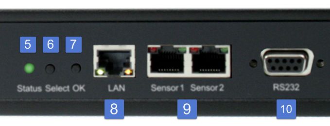
2

Expert Power Control 8221/8226   © 2019 GUDE Systems GmbH
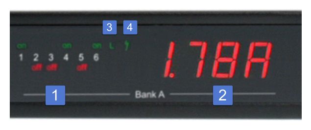
Table of contents

1.       Device Description                                                                                                                    5
   1.1         Security Advice ....................................................................................................... 6
   1.2         Content of Delivery ................................................................................................. 6
   1.3         Description ............................................................................................................. 6
   1.4         Installation ............................................................................................................. 7
   1.5         Dual-Circuit Characteristics ..................................................................................... 8
   1.6         Overvoltage Protection ........................................................................................... 9
   1.7     Technical Specifications .......................................................................................... 9
     1.7.1     Electrical Measurement ......................................................................................... 10
   1.8     Sensor .................................................................................................................. 10

2.       Operating                                                                                                                           14
   2.1         Operating the device directly ................................................................................ 15
   2.2         Control Panel ........................................................................................................ 15
   2.3     Maintenance ........................................................................................................ 17
     2.3.1    Maintenance Page ................................................................................................. 18
     2.3.2    Configuration Management .................................................................................. 19
     2.3.3    Bootloader Activation ............................................................................................ 21

3.       Configuration                                                                                                                       23
   3.1         Power Ports .......................................................................................................... 24
     3.1.1         Watchdog ............................................................................................................... 25
   3.2         Ethernet ............................................................................................................... 27
     3.2.1         IP Address ............................................................................................................... 27
     3.2.2         IP ACL ..................................................................................................................... 29
     3.2.3         HTTP ....................................................................................................................... 29
   3.3         Protocols .............................................................................................................. 30
     3.3.1         Console ................................................................................................................... 31
     3.3.2         Syslog ..................................................................................................................... 32
     3.3.3         SNMP ...................................................................................................................... 33
     3.3.4         Radius ..................................................................................................................... 34
     3.3.5         Modbus TCP ........................................................................................................... 35
   3.4         Sensors ................................................................................................................. 36
     3.4.1         Port Switching ........................................................................................................ 37
   3.5         E-Mail ................................................................................................................... 38
   3.6         Front Panel ........................................................................................................... 39

4.       Specifications                                                                                                                      40
   4.1         IP ACL ................................................................................................................... 41
   4.2         IPv6 ...................................................................................................................... 41

     3

Expert Power Control 8221/8226                                                                                                © 2019 GUDE Systems GmbH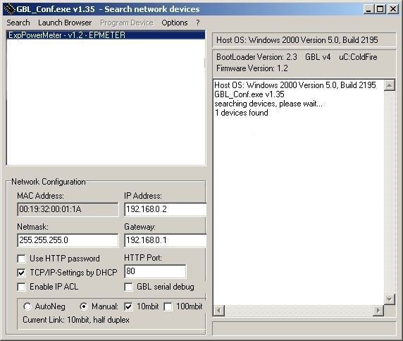
Table of contents

   4.3         Radius ................................................................................................................... 42
   4.4         Automated Access ................................................................................................ 42
   4.5     SNMP ................................................................................................................... 43
     4.5.1      Device MIB 8221 .................................................................................................... 45
     4.5.2      Device MIB 8226 .................................................................................................... 47
   4.6     SSL ........................................................................................................................ 49
   4.7     Console ................................................................................................................. 51
     4.7.1    Console Cmd 8221 ................................................................................................. 55
     4.7.2    Console Cmd 8226 ................................................................................................. 61
     4.7.3    Serial Console ......................................................................................................... 69
   4.8     Modbus TCP ......................................................................................................... 70
   4.9         Messages .............................................................................................................. 74

5.       Support                                                                                                                       76
   5.1         Data Security ........................................................................................................ 77
   5.2         Contact ................................................................................................................. 77
   5.3         Declaration of Conformity ..................................................................................... 78
   5.4         FAQ ...................................................................................................................... 78

Index                                                                                                                                  79

                                                                                                                                         4

Expert Power Control 8221/8226                                                                                           © 2019 GUDE Systems GmbH
Device Description

Device Description

1           Device Description
1.1         Security Advice

            · The device must be installed only by qualified personnel according to the following
              installation and operating instructions.
            · The manufacturer does not accept responsibility in case of improper use of the
              device and particularly any use of equipment that may cause personal injury or ma-
              terial damage.
            · The device contains no user-maintenable parts. All maintenance has to be per-
              formed by factory trained service personnel.
            · This device contains potentially hazardous voltages and should not be opened or
              disassembled.
            · The device can be connected only to 230V AC (50 Hz or 60 Hz) power supply sock-
              ets.
            · The power cords, plugs and sockets have to be in good condition. Always connect
              the device to properly grounded power sockets.
            · The device is intended for indoor use only. Do NOT install them in an area where ex-
              cessive moisture or heat is present.
            · Because of safety and approval issues it is not allowed to modify the device without
              our permission.
            · The device is NOT a toy. It has to be used or stored out of range of children.
            · Care about packaging material. Plastics has to be stored out of range of children.
              Please recycle the packaging materials.
            · In case of further questions, about installation, operation or usage of the device,
              which are not clear after reading the manual, please do not hesitate to ask our sup-
              port team.
            · Please, never leave connected equipment unattended, that can cause damage.
            · Connect only electrical devices that do not have limited on-time. I.e. in case of fail-
              ure, all connected appliances have to cope with a continuous on-time without caus-
              ing damage.

1.2         Content of Delivery

            The package includes:

            · Expert Power Control 8221-1/8226-1
            · 2 x Power Supply cable (IEC C19, max. 16 A)
            · CD-ROM with Manual and Softwaretools

1.3         Description

            The Expert Power Control 8221-1 / 8226-1 can switch 12 different load outputs (IEC
            C13, max. 10A), which each 6 outputs are fed from a mains connection (IEC C20,
            max. 16A) . The device has the following features:

            · Switching of 12 load outputs.
            · Energy Metering of the two mains connections and measurement of voltage, current,
              active power, reactive power, apparent power, frequency, phase angle, power factor.

                                                                                                               6

Expert Power Control 8221/8226                                                                    © 2019 GUDE Systems GmbH
Device Description
· Continuously and resettable energy meters on the mains connections.
· Energy Metering and meters for each port of the 12 load outputs and measurement
of voltage, current, active power, reactive power, apparent power, frequency , phase
angle, power factor per output (8226-1 only).
· Connecting of two optional external sensors to determine the temperature and hu-
midity, or a input switch.
· Two four-digit 7-segment LED displays (for display of current or temperature / humid-
ity of the external sensors).
· Separated over-voltage protection of the two mains connections (Overvoltage Pro-
tection).
· Startup delay, individually parametrizable for all load outputs.
· Individually adjustable watchdog function that switches power ports in dependency of
the accessibility of a device (network ping).
· Dual TCP/IP Stack with IPv4 and IPv6 support.
· Control and monitoring of the device via Ethernet with an integrated web server and
SNMP (v1, v2c and v3).
· Modbus TCP Support
· Console Commands with telnet support and serial interface.
· Generation of messages (E-Mail, Syslog and SNMP traps) and relay switching de-
pending on the energy measurement limits, resp. external sensors.
· Secure E-Mails.
1.4 Installation
1. 6 plain text displays (on/off) for the state of the outputs (Bank A or B)
2. Current power consumption of the Bank
3. LED indicator whether the Bank is connected to mains supply
4. LED indicator for Over Voltage Protection (green - surge protection is active, red -
inactive)
5. Status LED
6. Select button
7. Ok button
7
Expert Power Control 8221/8226 © 2019 GUDE Systems GmbHDevice Description
8. Ethernet connector (RJ45)
9. External sensor connectors (RJ45)
10. RS232 connector
11. Mains supply Bank B (IEC C20, max.16A)
12. 6 x Load outputs Bank B (IEC C13, max. 16A)
13. 6 x Load outputs Bank A (IEC C13, max. 16A)
14. Mains supply Bank A (IEC C20, max.16A)
Start-up the device
· Connect the two power cords (IEC C19, max. 16A) to the mains supply. The cable
connectors are secured as regards their type against unintentional loosening. They
must be inserted up to the stop, otherwise there is no secure connection. The plug
must not wobble in the socket, or there is no tight connection.
· Plug the network cable into the Ethernet socket (RJ45).
· If required, setup a serial connection to the RS232 port.
· Insert the optional external sensors into the sensor connectors.
· Connect the consumers with the load outputs (IEC C13, max. 10A).
1.5 Dual-Circuit Characteristics
The Expert Power Control 8221-1/8226-1 has two different input circuits (Banks A
and B). Therefore the mains supply A ( IEC C20, max. 16 A ) feeds the current to the
load outputs A1 to A6 (IEC C13, max. 10 A), resp. mains supply B feeds the current to
the load outputs B1 to B6 (IEC C13, max. 10 A ) . The electronics of the device works
when one of the two input circuits is supplied .
Twin Port
Two ports of different Banks but with the same number can be combined to a "twin
port". Then one port always participates in the switching status of the other port. In the
screenshot the ports A1 and B1 are combined, symbolized by the chain link icon. The
"Connect twin port" option can be found in the chapter "Configuration - Power Ports" .
8
Expert Power Control 8221/8226 © 2019 GUDE Systems GmbHDevice Description
Currentless Bank
If a bank is not receiving enough power smaller 70 V), a red "L" appears in the front
panel display, while a operating power supply shows a green " L". Upon entry of the
current loss all relays are switched off by the electronics, but the "On" and "Off" LEDs
still show the state of the relays when the supply was active. This is symbolized by the
flashing of the LEDs.
1.6 Overvoltage Protection
The device contains an overvoltage protection at each of the banks. The protection is
based on input side varistors with thermal fuse between phase (L) and neutral (N) to
protect the internal electronics and power ports with failure detection (permanently
triggered thermal fuse). The state of the protection is indicated on the front panel by a
green or red flash. A green flash means that the protection is active, a red flash sym-
bolizes that the overvoltage protection fails. In addition, the status of the overvoltage
protection can be seen on the Webpage (HTTP) and acquired with SNMP. Each surge
protection module is designed that it can derive a practical unlimited number of voltage
pulses in normal installation environments. In an environment with many energy rich
surge pulses it can result in permanent loss of function due to aging of the overvoltage
protection element.
Recovering of the overvoltage protection function can only be performed by the
manufacturer of the device. In the normal case, the device will continue to work even
after the failure of the protective function.
A signaling via E-Mail, Syslog or SNMP trap occurs only once during operation, ex-
actly at the moment in which the protection fails. In addition, at the start up of the
device a message is generated, when the overvoltage protection is not active.
1.7 Technical Specifications
Interfaces 1 x Ethernet port (RJ45)
1 x Serial connector (D-SUB, RS232)
2 x Mains supply (IEC C20, max.16 A)
2 x 6 Load outputs (IEC C13, max. 16
A)
2 x RJ45 for external sensor
Network connectivity 10/100 MBit/s 10baseT Ethernet
Protocols TCP/IP, HTTP/HTTPS, SNMP
v1/v2c/v3,
SNMP traps, Syslog, E-Mail (SMTP)
9
Expert Power Control 8221/8226 © 2019 GUDE Systems GmbHDevice Description
Power Supply internal power supply (90-265V AC / -
15% / +10%)
Overvoltage Protection 20 mm / 250 J varistor disk (300V AC)
· single peak current for 20/80us pulse 10000 A
· max. clamping voltage 20/80us pulse, 775 V
Ipk = 100 A
Environment
· Operating temperature 0°C - 50 °C
· Storage temperature -20°C - 70 °C
· Humidity 0% - 95% (non-condensing)
Case powder coated, galvanized steel sheet
Measurements 19" (inches), 1 Rack Unit, (Depth 195
mm)
Weight approx. 2.9 kg (8221-1)
approx. 3.0 kg (8226-1)
1.7.1 Electrical Measurement
typical fault tolerances for Ta=25°C, I=1Arms...16Arms, Un=90Vrms...265Vrms
Electrical Measurement Specification
Category Range Unit Resolu- Inaccuracy
tion (typical)
Voltage 90-265 V 0.01 < 1%
Current 0 - 16 A 0.001 < 1.5%
Frequency 45-65 Hz 0.01 < 0.03%
Phase -180 - +180 ° 0.1 < 1%
Active power 0 - 4000 W 1 < 1.5%
Reactive power 0 - 4000 Var 1 < 1.5%
Apparent power 0 - 4000 VA 1 < 1.5%
Power factor 0-1 - 0.01 < 3%
Energy Counter
Active Energy 9.999.999,999 kWh 0.001 < 1.5%
(total)
Active Energy 9.999.999,999 kWh 0.001 < 1.5%
(temporary)
1.8 Sensor
Two external sensors can be connected to the Expert Power Control 8221-1/8226-1.
The following sensors are currently available
10
Expert Power Control 8221/8226 © 2019 GUDE Systems GmbHDevice Description
Humidity/Temperature Sensor 7102 (End-of-Life)
Cable length
Connector RJ45
temperature range -20°C to +80°C, ±0,5°C (maximum) and ±0,3°C (typical)
air humidity range 0-100%, ±3% (maximum) and ±2% (typical)
(non-condensing))
11
Expert Power Control 8221/8226 © 2019 GUDE Systems GmbHDevice Description
Product Name 7101 7104 7105 7106
Cable length
Connector RJ45 RJ45 RJ45 RJ45
temperature range -20°C to +80°C at -20°C to +80°C at -20°C to +80°C at -20°C to +80°C at
±2°C (maximum) ±2°C (maximum) ±2°C (maximum) ±2°C (maximum)
and ±1°C (typical) and ±1°C (typical) and ±1°C (typical) and ±1°C (typical)
air humidity range - - 0-100%, ±3% 0-100%, ±3%
(non-condensing) (maximum) and (maximum) and
±2% (typical) ±2% (typical)
air pressure range - - - ± 1 hPa (typical)
(full) at 300 ... 1100
hPa, 0 ... +40 °C
air pressure range - - - ± 1.7 hPa (typical)
(ext) at 300 ... 1100
hPa, -20 ... 0 °C
Protection IP68 - - -
Product Name 7201 7202
Cable length - -
Connector RJ45 RJ45
temperature range -20°C to +80°C at ±2°C (max- -20°C to +80°C at ±2°C (max-
imum) and ±1°C (typical) imum) and ±1°C (typical)
air humidity range - 0-100%, ±3% (maximum) and
(non-condensing) ±2% (typical)
The sensors are automatically detected after connect. This is indicated by the green
LED on the sensor port that is lit permanently. The sensor values are displayed at
the "Control Panel" web page:
A click on the link in the "Name" column opens the display of the Min and Max values.
The values in a column can be reset using the "Reset" button. The "Reset" button in
the name column deletes all stored Min and Max values.
12
Expert Power Control 8221/8226 © 2019 GUDE Systems GmbHDevice Description 13 Expert Power Control 8221/8226 © 2019 GUDE Systems GmbH
Operating
Operating

2           Operating
2.1         Operating the device directly

            Port Switching
            The current status of the output is indicated by the color of the LED. Red indicates that
            the output is off, green shows that the output is on. On the device are the buttons "se-
            lect" and "ok". If you press "select", the LED will blink for the first output, ie the output is
            selected. Press "select" again to select the next output. Hold down the button "ok" for
            two seconds, then the status of the selected output is toggled.

            Display Information
            If no port is selected manually, repeatedly pressing the "ok" button will show the IP-ad-
            dress and the values of the external sensors on the display.

            Status-LED
            The Status LED shows the different states of the device:

            · red: The device is not connected to the Ethernet.
            · orange: The device is connected to the Ethernet and waits for data from the DHCP
              server.
            · green: The device is connected to the Ethernet and the TCP/IP settings are alloc-
              ated.
            · periodic blinking: The device is in Bootloader mode.

2.2         Control Panel

            Access the web interface: http://"IP-address" and log-in.

  15

Expert Power Control 8221/8226                                                                           © 2019 GUDE Systems GmbH
Operating
The web page provides an overview of the switching state, energy measurement val-
ues of the banks "A" and "B", as well as the external sensors, provided that they are
connected. When a single port is clicked at the Expert Power Control 8221-1/8226-1,
a panel with buttons to control a single port appear:
The Port icon is green when the relay is closed, or red in the open state. If a bank has
no voltage, the state is represented by a gray Port icon. An additional small clock icon
indicates that a timer is active. Timer can be activated by delay, reset or batch mode.
Two outputs configured as twin ports are connected by a chain icon.
An activated Watchdog is represented by an eye icon. An "X" means, that the address
that should be observed, could not be resolved. Two circular arrows show a booting
status.
In addition to the panel, the Expert Power Control 8226-1 shows the measured val-
ues of the selected port:
The ports can be switched manually with the "On" and "Off" buttons. If the port is
turned on, it can be turned off by pressing the "Reset" button, until after a delay it turns
itself on again. The delay time is determined by the parameter Reset Duration, which is
described in the chapter "Configuration - Power Ports 24 ". The "Close" button dis-
solves the panel again.
Batchmode
Each individual port can be set for a selectable period of time to the state "switch on"
or "switch off". After the selected time they are automatically switched to the second
preselected state.
16
Expert Power Control 8221/8226 © 2019 GUDE Systems GmbHOperating
Optionally the device can be switched via a Perl script or external tools like wget. More
information is available on our support wiki at www.gude.info/wiki.
2.3 Maintenance
The actual device generation with IPv6 and SSL allows all maintenance functions in
the web interface to be carried out on the Maintenance Page 18 .
Maintenance in the web interface
The following functions are available from the maintenance web page:
· Firmware Update
· Change the SSL certificate
· Load and save the configuration
· Restart the device
· Factory Reset
· Jump into the Bootloader
· Delete the DNS cache
Upload Firmware, Certificate or Configuration
On the Maintenance Page 18 , select the required file with "Browse .." in the sections
"Firmware Update", "SSL Certificate Upload" or "Config Import File Upload" and press
"Upload". The file is now transferred to the update area of the device and the contents
are checked. Only now, pressing the "Apply" button will permanently update the data,
or abort with "Cancel".
Only one upload function can be initiated with a reboot, eg. you cannot transmit
firmware and configuration at the same time.
If after a firmware update, the web page is not displayed correctly anymore, this
may be related to the interaction of Javascript with an outdated browser cache. If a
Ctrl-F5 does not help, it is recommended that you manually delete the cache in the
browser options. Alternatively, you can test start the browser in "private mode".
Actions in Bootloader mode
If the web interface of the device is no longer accessible, the device can be put into
Bootloader mode (see chapter Bootloader activation 21 ). The following functions can
be executed using the GBL_Conf.exe application:
· Set IPv4 address, net-mask and gateway
· Turn HTTP password on and off
· Turn IP-ACL on and off
· Factory Reset
· Jump into the bootloader (can be switched on and off)
· Restart the device
For devices with relays, entering or exiting the bootloader mode does not change
the state of the relays as long as the operating voltage is maintained.
17
Expert Power Control 8221/8226 © 2019 GUDE Systems GmbHOperating
The GBL_Conf.exe program is available free of charge on our website www.gude.info
and can also be found on the enclosed CD-ROM.
Interface GBL_Conf
To check the network settings with GBL_Conf.exe, start the program and choose "All
Devices" in the "Search" menu. From the list select the appropriate device. The lower
part of the left half of the window now shows the current network settings of the device.
If the IP address is displayed with the default settings (192.168.0.2), either no DHCP
server is present on the network, or there could be no free IP address assigned to it.
· Activate the Bootloader Mode (see Chapter Bootloader Mode) and choose in menu
"Search" the item "Bootloader-Mode Devices only"
· Enter the desired settings in the edit window and save them with "Save Config".
· Deactivate the boot loader mode for the changes to take effect. Select again "All
Devices" in the "Search" menu of GBL_Conf.exe.
The new network configuration is now displayed.
Factory Reset
The device can be reset to the factory default via the web interface from the Mainten-
ance Page 18 or from the Bootloader mode (see chapter Bootloader activation 21 ). All
TCP/IP settings are reset in this operation.
If a unit is set to factory defaults, an uploaded certificate or updated firmware will
be preserved.
2.3.1 Maintenance Page
This section provides access to important functions such as Firmware Update or Re-
start Device. It is advisable to set an HTTP password for this reason.
18
Expert Power Control 8221/8226 © 2019 GUDE Systems GmbHOperating
Firmware Update: Start a firmware update.
SSL Certificate Upload: Saves your own SSL certificate. See chapter "SSL 50 " for the
generation of a certificate in the right format.
Config Import File Upload: Loads a new configuration from a text file. To apply the new
configuration, a "Restart Device" must be executed after the "Upload".
Config File Export: Saves the current configuration in a text file.
Saving the configuration should only be carried out in an SSL connection, since it
contains sensitive password information (even if it is encrypted or hashed).
Restart Device: Restarts the device without changing the status of the relays.
Some functions such as a firmware update or changing of the IP-address and
HTTP settings require a restart of the device. A jump to the boot loader or a restart of
the device lead by no means to a change of the relay states.
Restore Fab Settings and Restart Device: Performs a restart and resets the device to
factory default 22 .
Enter Bootloader Mode: Jumps into bootloader mode, where additional settings can be
made with GBL_Conf.exe.
Flush DNS Cache: All entries in the DNS cache are discarded and address resolutions
are requested again.
2.3.2 Configuration Management
The device configuration can be saved and restored in the maintenance area 18 .
19
Expert Power Control 8221/8226 © 2019 GUDE Systems GmbHOperating
The "Config File Export" function can be used to save the current configuration as a
text file. The syntax used in the configuration file corresponds to the commands of the
Telnet console. If the configuration of a device is to be restored from a text file, load
the file with "Upload" and restart the device with "Restart Device".
Saving the configuration should only be carried out in an SSL connection, since it
contains sensitive password information (even if it is encrypted or hashed). For the
same reasons, it is advisable to carefully handle the generated configuration files when
archiving.
Editing the configuration file
It is possible to customize a saved configuration file with a text editor for your own
needs. For example, one scenario would be to use a script language to automate the
creation of many customized versions of a configuration, then equip a large number of
devices with an individualized configuration. Also Upload and restart with CGI com-
mands can be done in scripting languages. With use of the comment sign "#" you can
quickly hide single commands or add personal notes.
If you modify a configuration file manually, it is not always clear which limits are allowed
for parameters. After uploading and restarting, commands with invalid parameters are
ignored. Therefore, the generated configuration includes comments describing the
boundaries of the parameters. Where "range:" refers to a numeric value, and "len:" to a
text parameter. E.g:
email auth set 0 #range: 0..2
email user set "" #len: 0..100
The command "system fabsettings" from the beginning of a generated configuration
file brings the device into the factory state, and then executes the individual commands
that modify the configuration state. It may be desirable to make the changes relative to
the current configuration, and not out of the factory state. Then the "system fabset-
tings" should be removed.
No output of default values
The configuration file contains (with exceptions) only values which differ from the de-
fault. The command "system fabsettings" (go to the factory state) from the beginning of
a generated configuration file should not be removed, otherwise the device can get in-
completely configured.
Configuration via Telnet
The configuration files can in principle also be transferred in a Telnet session, but then
the settings are changed during operation, and not completely when restarting, as it
would have been the case with an upload. It can happen that events are triggered at
the same time as the device is configured. One should therefore:
a) disable the function
b) completely parametrize
20
Expert Power Control 8221/8226 © 2019 GUDE Systems GmbHOperating
c) reactivate the function
An example:
email enabled set 0
email sender set "" #len: 0..100
email recipient set "" #len: 0..100
email server set "" #len: 0..100
email port set 25
email security set 0 #range: 0..2
email auth set 0 #range: 0..2
email user set "" #len: 0..100
email passwd hash set "" #len: 0..100
email enabled set 1 #range: 0..1
2.3.3 Bootloader Activation
The configuration of the device from the application "GBL_Conf.exe" is only possible, if
the device is in Bootloader Mode.
Activation of the Bootloader Mode
1) via push button:
· Hold both buttons for 3 seconds
2) or
· Remove the power supply
· Hold down the "Select" button. If the push button is recessed, use a pin or paper clip
· Connect the operating voltage
3) by Software: (only if "Enable FW to BL" was previously activated in the
"GBL_Conf.exe" application)
· Start the "GBL_Conf.exe" program
· Do a network search with the "Search" menu action
· Activate in menu "Program Device" the item "Enter Bootloader"
4) via web interface:
Press "Enter Bootloader Mode" on the maintenance 18 web page.
Whether the device is in Bootloader mode, is indicated by the flashing of the status
LED, or it is shown in "GBL_Conf.exe" application after a renewed device search (ap-
pendix "BOOT-LDR" after the device name). In Bootloader mode the program
"GBL_Conf.exe" can disable the password and the IP ACL, perform a firmware update,
and restore the factory settings.
For devices with relays, entering or exiting the bootloader mode does not change
the state of the relays as long as the operating voltage is maintained.
Abandonment of the Bootloader Mode
1) via push button:
21
Expert Power Control 8221/8226 © 2019 GUDE Systems GmbHOperating
· Hold both buttons for 3 seconds (only if the device has 2 buttons)
2) or
· Remove and connect the power supply without operating a button
3) by Software:
· Start the "GBL_Conf.exe" application
· Do a network search with the "Search" menu action
· In menu "Program Device" activate the item "Enter Firmware"
Factory Reset
If the device is in bootloader mode, it can always be put back to its factory default. All
TCP/IP settings are reset in this operation.
If a unit is set to factory defaults, an uploaded certificate or updated firmware will
be preserved.
1) via push button:
· Activate the Bootloader Mode of the device
· Hold down the button (or the "Select" button for devices with 2 buttons) for 6
seconds. If the push button is recessed, use a pin or paper clip
· The status LED will blink in a fast rhythm, please wait until the LED blinks slowly
(about 5 seconds)
2) by Software:
· Activate the Bootloader Mode of the device
· "Start the GBL_Conf.exe" program
· In menu "Program Device" activate the item "Reset to Fab Settings"
· The status LED will blink in a fast rhythm, please wait until the LED blinks slowly
(about 5 seconds)
22
Expert Power Control 8221/8226 © 2019 GUDE Systems GmbHConfiguration
Configuration

3           Configuration

            TCP/IP configuration by DHCP
            After switching on the device is scanning on the Ethernet for a DHCP server and re-
            quests an unused IP address. Check the IP address that has been assigned and ad-
            just if necessary, that the same IP address is used at each restart. To turn off DHCP
            use the software GBL_Conf.exe or use the configuration via the web interface.

            To check the network settings with GBL_Conf.exe, start the program and choose "All
            Devices" in the "Search" menu. From the list select the appropriate device. The lower
            part of the left half of the window now shows the current network settings of the device.
            If the IP address is displayed with the default settings (192.168.0.2), either no DHCP
            server is present on the network, or there could be no free IP address assigned to it.

3.1         Power Ports

            Choose Power Port to configure: This field is used to select the power ports to be con-
            figured.

            Label: You can assign a name up to 15 characters for each of the power ports. Using
            the name, an identification of the the device connected to the port can be facilitated.

            Connect twinport: This option combines two relays of the same number of Bank A and
            Bank B. E.g. A2 and B2. By this connection a port always adopts the status of the con-
            nected port, so that both ports always have the same switching state.

            Start-up Monitoring

                                                                                                                24

Expert Power Control 8221/8226                                                                      © 2019 GUDE Systems GmbH
Configuration
It is important, that if necessary the condition of the power ports can be restored after a
power failure. Therefore each port can be configured with Initialization status to a spe-
cific start-up state. This start-up sequence can be carried out delayed by the parameter
Initialization Delay. There is in any case a minimum one-second delay between switch-
ing of ports.
Initialization status(coldstart): This is the port state (on, off, remember last state) the
port should be set when the device is turned on. The setting "remember last state"
saves the last manually set state of the power port in the EEPROM.
Initialization status(bank repower): Had a bank not enough voltage, and is now ad-
equately supplied again, the option "apply initialization status" leads to a repetition of
the start-up sequence for this bank. Is "remain in current state" selected, the port state
that is shown on display and web page is implemented.
Initialization delay: Here can be configured how long the port should wait to switch to its
defined state after the device is turned on. The delay may last up to 8191 seconds.
This corresponds to a period of approx. two hours and 20 minutes. A value of zero
means that the initialization is off.
Repower delay: When this feature is enabled (value greater than 0), the power port will
switch itself on again a specified time after it has been disabled. Unlike the "Reset" but-
ton this function applies to all switch actions, including SNMP, or an optional serial in-
terface.
Reset Duration: When the "Reset" button is triggered, the device turns the power port
off, waits for the time entered here (in seconds) and turns the power port on.
Ignore Powerloss on Bank x: The power ports of bank x are not automatically switched
off when a voltage failure is detected, they keep their actual state.
This can lead to an increased total current consumption when the voltage is com-
ing back, since the activated connected devices are simultaneously turned on again.
Activation of this option makes sense, if the input voltage of the device deviates
strongly from the sinusoidal shape. The internal signal evaluation might then erro-
neously assume a voltage drop, because the zero-crossing characteristic typical for si-
nusoidal voltage curves is absent. One possible source of such non-sinusoidal voltage
supply may be a simple UPS that produces rectangular output voltages.
3.1.1 Watchdog
The watchdog feature enables to monitor various remote devices. Therefore either
ICMP pings or TCP pings are sent to the device to be monitored. If these pings are not
answered within a certain time (both the time and the number of attempts can be set),
the port is reset. This allows e.g. to automatically restart not responding server or NAS
systems. The mode IP master-slave port allows you to switch a port depending on the
availability of a remote device.
When a watchdog is activated it presents various information in the Control Panel. The
information is color-coded.
· Green text: The watchdog is active and regularly receives ping replies.
· Orange text: The watchdog is currently enabled, and waits for the first Ping re-
sponse.
· Red text: The watchdog is active and receives no ping replies anymore from the con-
figured IP address.
After the watchdog has been enabled, the display remains orange until the watchdog
receives a ping response for the first time. Only then the watchdog is activated. Even
after triggering a watchdog and a subsequent power port reset, the display will remain
25
Expert Power Control 8221/8226 © 2019 GUDE Systems GmbHConfiguration
orange until the device is rebooted and responds again to ping requests. This will pre-
vent a premature watchdog reset of the port, e.g. when a server needs a long time for
a file check.
You can monitor devices on your own network, as well as devices on an external net-
work, e.g. the operating status of a router.
Enable watchdog: Enables the watchdog function for this Power Port.
Watchdog type: Here you can choose between the monitoring by ICMP pings or TCP
pings.
· ICMP Pings: The classic ping (ICMP echo request). It can be used to check the ac-
cessibility of network devices (for example, a server).
· TCP Pings: With TCP pings, you can check if a TCP port on the target device would
accept a TCP connect. Therefore a non-blocked TCP port should be selected. A
good choice would be port 80 for http or port 25 for SMTP.
TCP port: Enter the TCP port to be monitored. When using ICMP pings this is not
needed.
Hostname: The name or IP address of the monitored network device.
Ping interval: Select the frequency (in seconds) at which the ping packet is sent to
each network device to check its operating status.
Ping retries: After this number of consecutive unanswered ping requests the device is
considered inactive.
Watchdog mode: When Reset port when host down is enabled, the Power Port is
turned off and switched back on after the time set in Reset Duration. In mode Switch
off once when host down the Power Port remains disabled.
26
Expert Power Control 8221/8226 © 2019 GUDE Systems GmbHConfiguration
At the default setting (Infinite wait for booting host after reset) the watchdog monitors
the connected device. When there is no longer a reply after a set time, the watchdog
performs the specified action, usually a reset of the Power Port. Now the watchdog
waits until the monitored device reports again on the network. This may take several
minutes depending on the boot duration of the device. Only when the device is access-
ible from network again, the watchdog is re-armed. If the option Repeat reset on boot-
ing host after x ping timeout is enabled, this mechanism is bypassed. Now the watch-
dog is re-activated after N Ping intervals (input field ping timeouts).
When enabling the IP master-slave mode, the port is switched depending on the avail-
ability of a remote device. Depending on the configuration, the port is switched on
when the terminal is reachable, or vice versa.
The option Repeat reset on booting host after x ping timeout has the following pit-
fall: If a server, that is connected to the monitored Port is in need for a long boot pro-
cess (e.g. it is doing a file system check), the server would probably exceed the trip-
ping time of the watchdog. The server would be switched off and on again, and the file
system check is restarted. This would be repeated endlessly.
3.2 Ethernet
3.2.1 IP Address
Hostname: Here you can enter a name with up to 63 characters. This name will be
used for registration on the DHCP server.
Special characters and umlauts can cause problems in the network.
IPv4 Address: The IP address of the device.
IPv4 Netmask: The network mask used in the network.
IPv4 Gateway address: The IP address of the gateway.
IPv4 DNS address: The IP address of the DNS server.
27
Expert Power Control 8221/8226 © 2019 GUDE Systems GmbHConfiguration
Use IPv4 DHCP: Select "yes" if the TCP/IP settings should be obtained directly from
the DHCP server: When the function is selected, each time the device powers up it is
checked if a DHCP server is available on the network. If not, the last used TCP/IP set-
ting will be used further.
Use IPv6 Protocol: Activates IPv6 usage.
Use IPv6 Router Advertisement: The Router Advertisement communicates with the
router to make global IPv6 addresses available.
Use DHCP v6: Requests from an existing DHCPv6 server addresses of the configured
DNS server.
Use manual IPv6 address settings: Activates the entry of manual IPv6 addresses.
IPv6 status: Displays the IPv6 addresses over which the device can be accessed, and
additionally DNS and router addresses.
For IP changes a firmware reset is required. This can be done in the Maintenance
web page. A restart of the device leads by no means to a change of the relay states.
Manual IPv6 Configuration
The input fields for the manual setting of IPv6 addresses allow you to configure the
prefix of four additional IPv6 device addresses, and to set two DNS addresses, and a
gateway.
28
Expert Power Control 8221/8226 © 2019 GUDE Systems GmbHConfiguration
3.2.2 IP ACL
Reply ICMP ping requests: If you enable this feature, the device responds to ICMP
pings from the network.
Enable IP filter: Enable or disable the IP filter here. The IP filter represents an access
control for incoming IP packets.
Please note that when IP access control is enabled HTTP and SNMP only work if
the appropriate servers and clients are registered in the IP access control list.
If you choose a wrong IP ACL setting and locked yourself out, please activate the
Bootloader Mode and use GBL_Conf.exe to deactivate the IP ACL. Alternatively, you
can reset the device to factory default.
3.2.3 HTTP
29
Expert Power Control 8221/8226 © 2019 GUDE Systems GmbHConfiguration
HTTP Server option: Selects whether access is possible only with HTTP, HTTPS, or
both.
Server port HTTP: Here can be set the port number of the internal HTTP. Possible val-
ues ?
are from 1 to 65534 (default: 80). If you do not use the default port, you must ap-
pend the port number to the address with a colon to address the device from a web
browser. Such as: "http://192.168.0.2:800"
Server port HTTPS; The port number to connect the web server via the SSL (TLS) pro-
tocol.
Enable Ajax autorefresh: If this is activated, the information of the status page is auto-
matically updated via http request (AJAX).
For some HTTP configuration changes a firmware reset is required. This can be
done in the Maintenance web page. A restart of the device leads by no means to a
change of the relay states.
Enable password protection: Password access protection can be activated. If the ad-
min password is assigned, you can only log in by entering this password to change set-
tings. Users can log in by entering the user password in order to query the status in-
formation and initiate switching operations.
Use radius server passwords: Username and password are validated by a Radius
Sever.
Use locally stored passwords: Username and password are stored locally. In this case,
an admin password and a user password must be assigned. The password can have a
maximum of 31 characters. The name "admin" and "user" are provided for the user
name in the password entry mask of the browser. In factory settings, the password for
the admin is set to "admin" or "user" for the user password.
If the password mask is redisplayed, only four "bullets" are shown as a symbolic
placeholder, since for security reasons the device never stores the password itself, but
only the SHA2-256 hash. If you want to change a password, the complete password
must always be re-entered.
If you have forgotten your password, please activate the bootloader mode and
then turn off the password prompt in GBL_Conf.exe.
3.3 Protocols
30
Expert Power Control 8221/8226 © 2019 GUDE Systems GmbHConfiguration
3.3.1 Console
Enable Telnet: Enables Telnet console .
Telnet TCP port: Telnet sessions are accepted on this port.
Raw mode: The VT100 editing and the IAC protocol are disabled.
Activate echo: The echo setting if not changed by IAC.
Active negotiation: The IAC negotiation is initiated by the server.
Require user login: Username and password are required.
Delay after 3 failed logins: After 3 wrong entries of username or password, the next lo-
gin attempt is delayed.
Use radius server passwords: Username and password are validated by a Radius
Sever.
Use locally stored passwords: Username and password are stored locally.
31
Expert Power Control 8221/8226 © 2019 GUDE Systems GmbHConfiguration
Enable serial console: Enables the serial console.
Raw mode: The VT100 editing is disabled.
Activate echo: The echo setting.
Enable binary KVM protocol: Additionally activates the KVM protocol.
Enable UTF8 support: Enables character encoding in UTF8.
Require user login: Username and password are required.
Delay after 3 failed logins: After 3 wrong entries of username or password, the next lo-
gin attempt is delayed.
Use radius server passwords: Username and password are validated by a Radius
Sever.
Use locally stored passwords: Username and password are stored locally.
3.3.2 Syslog
Enable Syslog: Enables the usage of Syslog Messages.
Syslog Server: If you have enabled Syslog Messages, enter the IP address of the
server to which the syslog information should be transmitted.
32
Expert Power Control 8221/8226 © 2019 GUDE Systems GmbHConfiguration
3.3.3 SNMP
SNMP-get: Enables the acceptance of SNMP-GET commands.
SNMP-set: Allows the reception of SNMP-SET commands.
SNMP UDP Port: Sets the UDP port where SNMP messages are received.
Enable SNMP v2: Activates SNMP v2.
Because of security issues, it is advisable to use only SNMP v3, and to disable
SNMP v2. Accesses to SNMP v2 are always insecure.
Community public: The community password for SNMP GET requests.
Community private: The community password for SNMP SET requests.
Enable SNMP v3: Activates SNMP v3.
SNMP v3 Username: The SNMP v3 User Name.
SNMP v3 Authorization Algorithm: The selected Authentication Algorithm.
SNMP v3 Privacy Algorithm: SNMP v3 Encryption Algorithm..
If the password mask is redisplayed, only four "bullets" are shown as a symbolic
placeholder, since for security reasons the device never stores the password itself, but
only the key formed using the Authorization Algorithm. If you want to change a pass-
word, the complete password must always be re-entered.
33
Expert Power Control 8221/8226 © 2019 GUDE Systems GmbHConfiguration
The calculation of the password hashes varies with the selected algorithms. If the
Authentication or Privacy algorithms are changed, the passwords must be re-entered
in the configuration dialog. "SHA-384" and "SHA512" are calculated purely in software.
If "SHA-512" is set on the configuration page, the time for the key generation may take
once up to approx. 45 seconds.
Send SNMP traps: Here you can specify whether, and in what format the device should
send SNMP traps.
SNMP trap receiver: You can insert here up to eight SNMP trap receiver.
MIB table: The download link to the text file with the MIB table for the device.
More information about SNMP settings are available from our support or can be found
on the Internet at www.gude.info/wiki.
3.3.4 Radius
Enable Radius Client: Enables validation over Radius.
Use CHAP: Use CHAP password encoding.
Use Message Authentication: Adds the "Message Authentication" attribute to the
Authentication Request.
Primary Server: Name or IP address of the Primary Radius server.
Shared secret: Radius Shared Secret.
Timeout: How long (in seconds) will be waited for a response from an Authentication
Request.
Retries: How often an authentication request is repeated after a timeout.
34
Expert Power Control 8221/8226 © 2019 GUDE Systems GmbHConfiguration
Use Backup Server: Activates a Radius Backup server.
Backup Server: Name or IP address of the Radius Backup server.
Shared secret: Radius Shared Secret.
Timeout: How long (in seconds) will be waited for a response from an Authentication
Request.
Retries: How often an authentication request is repeated after a timeout.
Test Username: Username input field for Radius test.
Test Password: Password input field for Radius test.
The "Test Radius Server" function allows you to check whether a combination of User-
name and Password is accepted by the configured Radius Servers.
3.3.5 Modbus TCP
Enable Modbus TCP: Enables Modbus TCP support.
Modus TCP port: The TCP/IP port number for Modbus TCP.
35
Expert Power Control 8221/8226 © 2019 GUDE Systems GmbHConfiguration
3.4 Sensors
Sensor: Selects a type of sensor to configure it. The first digit "1" indicates the number
of the sensor port (only important for devices with more than one sensor port). This is
followed by the sensor name, and the changeable sensor name.
Sensor Name: Changeable name for this sensor. Temperature and humidity can have
different names, even if they are from the same sensor.
Select Sensor Field: Selects a data channel from a sensor.
Enable ... Messages: Enables the generation of sensor messages.
Maximum/Minimum value: Here you can choose whether, and at what Maximum/Min-
imum temperature or humidity measurements limits the alerts are send via SNMP
traps, syslog or E-Mail.
Hysteresis: This describes the margin of when an event is generated after the meas-
ured value has crossed the chosen limit.
Message channels: Enables the generation of messages on different channels.
Min/Max measurement period: Selects the time range for the sensor min/max values
on the overview web page.
Enable beeper for AC alarms: Activates the beeper for all AC limit messages.
Enable beeper for sensor alarms: Activates the beeper for all sensor limit messages.
36
Expert Power Control 8221/8226 © 2019 GUDE Systems GmbHConfiguration
Hysteresis Example:
A Hysteresis value prevents that too much messages are generated, when a sensor
value is jittering around a sensor limit. The following example shows the behavior for a
temperature sensor and a hysteresis value of "1". An upper limit of "50 °C" is set.
Example:
49.9 °C - is below the upper limit
50.0 °C - a message is generated for reaching the upper limit
50.1 °C - is above the upper limit
...
49.1 °C - is below the upper limit, but in the hysteresis range
49.0 °C - is below the upper limit, but in the hysteresis range
48.9 °C - a message is generated for underrunning the upper limit inclusive hysteresis
range
...
3.4.1 Port Switching
Depending on the measured Current and the measured sensor values, switching ac-
tions can be triggered. During operation, the actions configured for crossing the limits
are executed. For example, when a value moves from the range "above max value" in-
side the range "below max value", the action defined for "below max value" is per-
formed. In the case of device start, configuration or plug-in of the sensor, the actions
corresponding to the range in which the current temperature is located are switched.
Example with "Maximum value" of 65 °C, "Minimum value" of 25 °C and hysteresis of 3
°C. The dotted line shows the hysteresis.
37
Expert Power Control 8221/8226 © 2019 GUDE Systems GmbHConfiguration
Actions during configuration, device start or plugging in the sensor (for given example):
actual temperature actions
during configuration
70 °C Port A1 Off (above max) + Port A2 On (above min)
45 °C Port A1 On (below max) + Port A2 On (above min)
20 °C Port A1 On (below max) + Port A2 Off (below min)
Action matrix during operation when limit values are exceeded (for given example):
to "above max" to "below max" to "above min" to "below min"
from "above - A1 On A1 On A1 On + A2 Off
max"
from "below max" A1 Off - - A2 Off
from "above min" A1 Off - - A2 Off
from "below min" A1 Off + A2 On A2 On A2 On -
Only the switching operations for which actions have been defined, are triggered. If
no "On" or "Off" action is defined for a port, the port can never reach this state by ex-
ceeding sensor values. Unless it is the initial state.
3.5 E-Mail
Enable E-Mail: Activates the E-Mail dispatch of messages.
Sender address: The E-Mail address of the sender.
Recipient address: The E-Mail address of the recipient. Additional E-Mail addresses,
separated by comma, can be specified. The input limit is 100 characters.
SMTP Server: The SMTP IP-address of the E-Mail server. Either as FQDN, e.g:
"mail.gmx.net", or as IP-address, e.g: "213.165.64.20". If required, attach a designated
port, e.g: "mail.gmx.net:25".
38
Expert Power Control 8221/8226 © 2019 GUDE Systems GmbHConfiguration
SMTP server port: The port address of the E-Mail server. In the normal case this
should be the same as the default, that is determined by the setting SMTP Connection
Security.
SMTP Connection Security: Transmission via SSL or no encryption.
SMTP Authentification (password): Authentication method of the E-Mail Server.
Username: User name that is registered with the SMTP E-Mail server.
Set new password: Enter the password for the login to the E-Mail server.
Repeat password: Enter the password again to confirm it.
If the password mask is redisplayed, only four "bullets" are shown as a symbolic
placeholder, since for security reasons the password is never shown itself. If you want
to change a password, the complete password must always be re-entered.
E-Mail Logs: Logging of E-Mail system messages.
3.6 Front Panel
Button Lock: Disables the front buttons (activates the key lock) with the exception of
the bootloader activation.
Dark Display: The 7-segment display remains dark. Front button activity temporarily
switches the display on.
Default Display: Selects what sensor is displayed in the display.
39
Expert Power Control 8221/8226 © 2019 GUDE Systems GmbHSpecifications
Specifications

4           Specifications
4.1         IP ACL

            IP Access Control List

            The IP Access Control List (ACL IP) is a filter for incoming IP packets. If the filter is
            active, only the hosts and subnets whose IP addresses are registered in the list, can
            contact via HTTP or SNMP, and make changes. For incoming connections from unau-
            thorized PCs, the device is not completely transparent. Due to technical restraints, a
            TCP/IP connection will be accepted at first, but then rejected directly.

            Examples:

             Entry in the IP ACL      Meaning

             192.168.0.123            the PC with IP Address "192.168.0.123" can access the device

             192.168.0.1/24           all devices of subnet "192.168.0.1/24" can access the device

             1234:4ef0:eec1:0::/64    all devices of subnet "1234:4ef0:eec1:0::/64" can access the device

                If you choose a wrong IP ACL setting and locked yourself out, please activate the
            Bootloader Mode and use GBL_Conf.exe to deactivate the IP ACL. Alternatively, you
            can reset the device to factory default.

4.2         IPv6

            IPv6 Addresses
            IPv6 addresses are 128 bit long and thus four times as long as IPv4 addresses. The
            first 64 bit form a so-called prefix, the last 64 bit designate a unique interface identifier.
            The prefix is composed of a routing prefix and a subnet ID. An IPv6 network interface
            can be reached under several IP addresses. Usually this is the case under a global ad-
            dress and the link local address.

            Address Notation
            IPv6 addresses are noted in 8 hexadecimal blocks at 16 bit, while IPv4 normally is
            noted in decimal. The seperator is a colon, not a period.

            E.g.: 1234:4ef0:0:0:0019:32ff:fe00:0124

            Leading zeros may be omitted within a block. The previous example can be rewritten
            as:

            1234:4ef0:0:0:19:32ff:fe00:124

            One may omit one or more successive blocks, if they consist of zeros. This may be
            done only once within an IPv6 address!

            1234:4ef0::19:32ff:fe00:124

  41

Expert Power Control 8221/8226                                                                          © 2019 GUDE Systems GmbH
You can also read