Externally Heated & Blower Purge Desiccant Dryers - Models TWP/TWB201 - TWP/TWB7501 - Parker ...
←
→
Page content transcription
If your browser does not render page correctly, please read the page content below
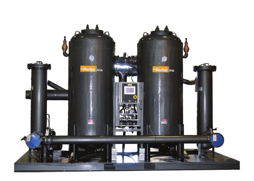
Externally Heated & Blower Purge
Desiccant Dryers
Models TWP/TWB201 – TWP/TWB7501
User Manual

                         1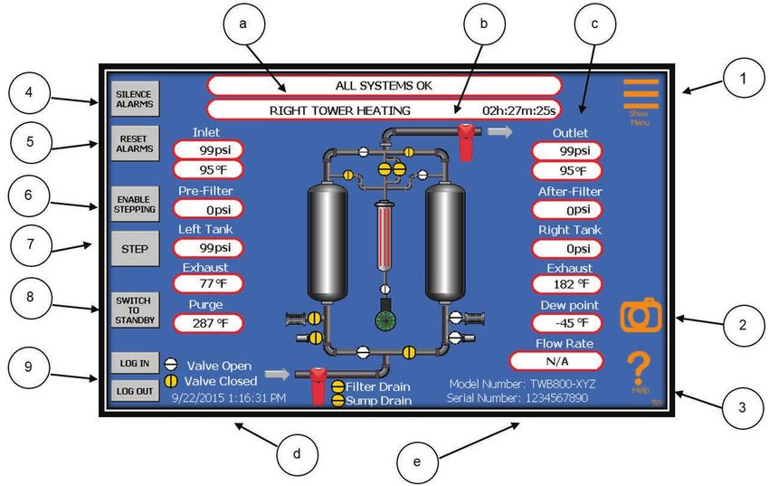
TWP/TWB201 – TWP/TWB7501

     These instructions must be thoroughly read and understood before installing and operating
     this product. Failure to operate this product in accordance with the instructions set forth in this
     manual can lead to unsafe operating conditions and may void warranty. For additional infor-
     mation, refer to this manual or contact the factory for recommendations. Please have the dryer
     serial number and model ready when contacting the factory.

     Factory Contact Information

     Phone 1-800-343-4048

     For pricing, availability, and purchase orders: GSForders@parker.com

     For technical support and aftermarket: FAFparts@parker.com

     For product applications and technical sales: FAFquotes@parker.com

                                                      2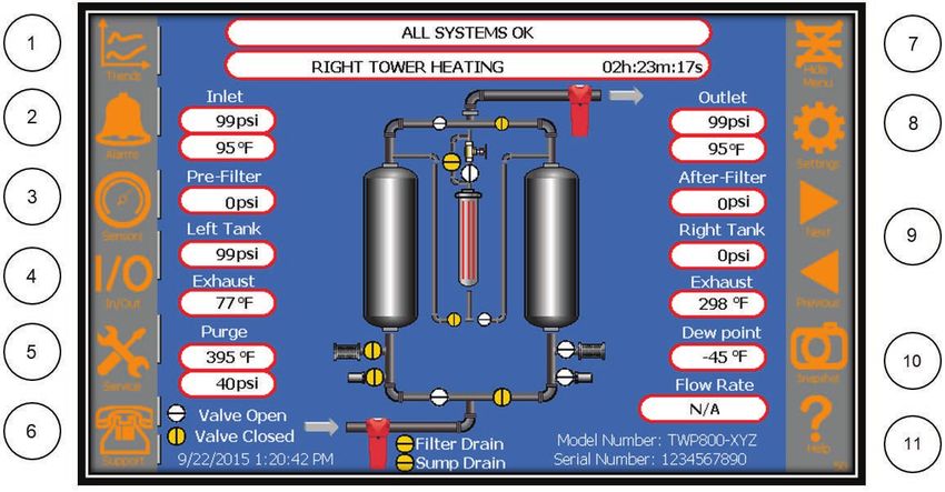
TWP/TWB201 – TWP/TWB7501

     Contents

     Safety and Precautions									4

     Installation											5

     General Operation										8

     Flow Schematics										10

     Wiring Diagrams										17

     Start Up											26

     Timing Configuration										27

     Manual Stepping										28

     Controller Display & Operation								28

     Communications										48

     Shutdown											56

     Maintenance											56

     Spare Parts Lists										58

     Troubleshooting										79

     Technical Specifications									81

                           3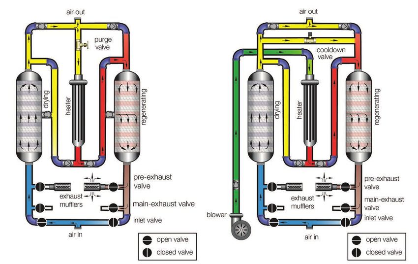
TWP/TWB201 – TWP/TWB7501

     SAFETY AND PRECAUTIONS

     Use EXTREME CAUTION when working in the vicinity of the dryer. Adhere to all warning labels on dryer.
     Relieve pressure before servicing dryer or associated equipment.

     Disconnect power before servicing dryer.

     Always wear eye protection when in the vicinity of the dryer. Ear protection is recommended, especially if the dryer is
     being operated without mufflers. Even when mufflers are used, a desiccant vessel blowing down to atmosphere will
     raise particles, create more noise than during “normal” operation and may startle an individual not familiar with this
     portion of the operation.

     The dryer is uses heat to regenerate the desiccant. Any dryer surface may reach temperatures up to 350°F. Do not
     touch hot surfaces. Partial insulation is provided to maximize dryer performance. The standard insulation does not
     provide complete personnel protection or 100% thermal efficiency.

     The emergency stop button will cut off 120V control voltage only. Supply voltage is not disconnected.

     In the case of an overpressure situation there is a safety relief valve installed on each desiccant vessel designed to
     protect the equipment. If the valves are pointed in a hazardous location to operators after dryer installation, they
     should be piped to a safe location.

     Dryers are designed for fail safe operation. In the event of a power failure, the inlet valves will fail in the open or last
     position and the exhaust valves will fail closed. Compressed air will continue to flow through the dryer. When power
     is restored, the cycle will continue on from where it left off at the time of the power loss.

     Automatic or manual drain valves will eject water, oil, particulates, and air under partial pressure when operated.
     Proper precautions must be taken.

     Condensate drainage from compressed air systems may contain oil or other contaminants. Follow all applicable
     regulations for safe handling and disposal.

     Various component failures could cause large air loss and subsequent pressure drop. Preventative maintenance
     should be performed to reduce this possibility. If this situation occurs, bypass the dryer immediately to restore
     flow and pressure.

     Oil in the desiccant bed combined with high regeneration temperature may create a potential for fire or
     explosion. Proper cooling, pre-filtration, and condensate drainage must be maintained to reduce the possibility
     of oil contamination.

     Activated alumina dust is considered a nuisance dust. Proper precautions should be taken when handling desiccant.
     For more information and for other types of desiccant, refer to the applicable Safety Data Sheet. For disposal of
     used desiccant, refer to the local codes and regulations.

     NOTE: desiccant contaminated with oil or other foreign substances may be covered under disposal regulations for
     the contaminant.

     Heated dryers are designed with a cooling cycle after heated regeneration to alleviate high temperatures from the
     regenerated desiccant and vessel. It is normal for residual heat to remain in the regenerated vessel. Temperatures
     of 200-350°F may be seen at switchover. The residual heat will dissipate quickly once the tower is online at full flow.
     Downstream piping and components must be suitable for the elevated temperatures.

     DOWNSTREAM AIR TEMPERATURE MAY EXCEED 200°F FOR A DURATION OF 15 MINUTES AFTER DRYING
     VESSEL SWITCHOVER! TEMPERATURE CAN EXCEED 350°F AT LOWER FLOW!

                                                                  4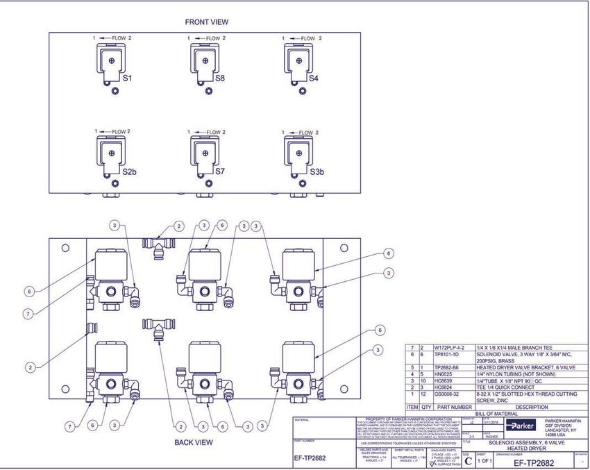
TWP/TWB201 – TWP/TWB7501

     INSTALLATION
     Inspect the dryer upon receipt for any damage that may have occurred during shipment.

     Each desiccant dryer is supplied with a User Manual, dryer general arrangement drawing, and ASME pressure
     vessel U1A data reports (where applicable).

     The initial charge of desiccant is included with the dryer. Ensure vessels are filled with desiccant prior to startup.
     Models 2001 and larger include desiccant shipped separately in 25 lb bags to be installed by the user at the site.
     Smaller dryers are shipped with desiccant installed.

     Exhaust mufflers are supplied for each dryer. A quantity of two mufflers are shipped attached to the dryer, unin-
     stalled, for models 201 and larger. Mufflers should not be installed until after startup to allow excess desiccant dust
     to be cleared from the dryer and not prematurely clog the new mufflers.

     The dewpoint sensor (optional) is shipped in a small container attached to the dryer. Take care not to misplace
     before installing.

     If placed in storage, place in a location protected from the environment. If stored outside, it is recommended that the
     dryer be underneath a shelter and be shrink wrapped or crated to protect against rain. Desiccant dryers should not
     be stored in a location exposed to freezing temperatures or direct sunlight. Dryers designed for outdoor use should
     not be placed outside until ready for operation. All plugs and flange covers should remain in place until the dryer is
     ready to be installed. Desiccant bags should remain in original closed packaging and be stored in a dry environment
     until dryer is ready for operation. Dryers with desiccant installed should be stored in a dry environment.

     The dryer should be moved using a pallet jack or fork truck. Desiccant dryers are tall and top heavy. Use caution
     while moving the equipment to avoid tipping over. Many dryers have desiccant vessels equipped with lifting lugs.
     DO NOT USE THE VESSEL LIFTING LUGS TO LIFT THE DRYER. They are only used to lift an empty vessel and are
     not designed to hold the weight of the equipment.

     Install in an area with an ambient temperature range of 40°F to 100°F. The area should be well lit and ventilated. It is
     recommended to leave a minimum of four feet around all sides of the dryer for maintenance. Ensure that the dryer is
     stable and properly secured on a vibration free floor before operation.

     If installed outdoors, the desiccant dryer should be installed in an area protected from the effects of weather.
     Locate under a roof if possible. Avoid direct sunlight so that the control display does not become damaged and can
     be clearly read. If installed in an area with below freezing temperatures, proper heat trace and freeze protection must
     be added to the equipment.

                                                                 5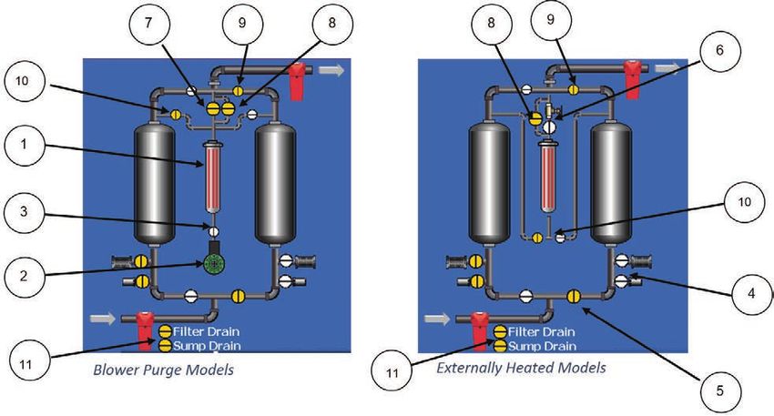
TWP/TWB201 – TWP/TWB7501

     There are several connection points on the dryer. Make sure each connection is made prior to startup.

       1. Air in connection – Will be marked on the dryer with a tag. Use piping suitable for the pressure and
     	  temperature class.

       2. Air out connection – Will be marked on the dryer with a tag. Use piping suitable for the pressure and
     	  temperature class.

          3. Prefilter drain connection – Located near the prefilter and labeled. Drain discharge is under pressure
     	  equal to the system and must use piping suitable for the pressure and temperature class if piped to
     	  another location. A coalescer type prefilter must be installed before the desiccant dryer if not supplied
     	  with the dryer. It is critical to the performance of the dryer to protect the desiccant bed from oil bulk
     	  moisture contamination.

       4. Dewpoint sensor (Power Lock options only) - Located near the prefilter and labeled. Drain discharge
     	  is under pressure equal to the system and must use piping suitable for the pressure and temperature
     	  class if piped to another location. A coalescer type prefilter must be installed before the desiccant dryer
     	  if not supplied with the dryer. It is critical to the performance of the dryer to protect the desiccant bed
     	  from oil bulk moisture contamination.

                                                                                     ELECTRICAL CONNECTOR

                                                                                     DEWPOINT SENSOR

                                   SAMPLE LINE
                                 ISOLATION VALVE

                                                                                        SAMPLE LINE
                                                                                        BLEED TUBE

     5. Power supply – Bring power to the high voltage panel. Verify voltage, phase, and frequency of power
        supply matches dryer design by checking the serial label. Check that power supply is sufficient for amp
        rating on serial label. Short circuit protection is the responsibility of the owner.

     Mufflers are included with the dryer to reduce noise level only. They are not required for normal operation and
     should not be installed for initial startup. The exhaust may be piped to another location to further reduce noise,
                                                                   MATERIAL                PROPERTY OF PARKER-HANNIFIN CORPORATION
                                                                                                                                  PARKER HANNIFIN
                                                                                                                                                              DRAWN BY
                                                                                     THIS DOCUMENT CONTAINS INFORMATION THAT IS CONFIDENTIAL AND PROPRIETARY TO
                                                                                                                                  FAF DIVISION
                                                                                     PARKER HANNIFIN, AND IS FURNISHED ON THE UNDERSTANDING THAT THE DOCUMENT
                                                                                                                                                                     JZ
                                                                                                                                                                             DATE
                                                                                                                                                                              1/12/2016

     but must not restrict purge air or dryer performance will suffer. The following considerations must be taken when
                                                                                     AND THE INFORMATION IT CONTAINS WILL NOT BE COPIED OR DISCLOSED TO OTHERS
                                                                                                                                  LANCASTER, NY
                                                                                     OR USED FOR ANY PURPOSE OTHER THAN CONDUCTING BUSINESS WITH PARKER, AND
                                                                                     WILL BE RETURNED AND ALL FURTHER USE DISCONTINUED UPON REQUEST BY PARKER. SCALE
                                                                                                                                  14086 USA                                  UNITS
                                                                                     COPYRIGHT IS THE FIRST YEAR INDICATED ON THIS DOCUMENT. ALL RIGHTS RESERVED.  3:50           INCHES

     piping the exhaust.                                           PART NUMBER
                                                                                                               CONSTRUCTIONAL: ELECTRICAL
                                                                                       USE CORRESPONDING TOLERANCES UNLESS OTHERWISE SPECIFIED

                                                                                      WELDED PARTS AND              ASSEMBLY TW1200
                                                                                                               SHEET METAL PARTS         MACHINED PARTS
                                                                                                                                                              TITLE

                                                                                       SALES DRAWINGS                                                                     SHEET                            REVISION
                                                                                                                                         2 PLACE (.00): ±.01   SIZE                    DRAWING NUMBER
                                                                   E-TW1200FY14NNN      FRACTIONS: ± 1/4     ALL TOLERANCES: ± 1/64      3 PLACE (.000): ±.005

               TO 10 FEET, SAME PIPE DIAMETER SIZE AS DRYER EXHAUST VALVE.
                                                                                          ANGLES: ± 3º            ANGLES: ± 2º
                                                                                                                                       125
                                                                                                                                             ANGLES ± 1/2~
                                                                                                                                           Ra SURFACE FINISH   C          3 OF 3
                                                                                                                                                                                       TW1200FY14NNN-MAN       -

               TO 25 FEET, ONE PIPE DIAMETER SIZE LARGER THAN DRYER EXHAUST VALVE.

               TO 50 FEET, TWO PIPE DIAMETER SIZES LARGER THAN DRYER EXHAUST VALVE.

               TO 100 FEET, THREE PIPE DIAMETER SIZES LARGER THAN DRYER EXHAUST VALVE.

                                                                      6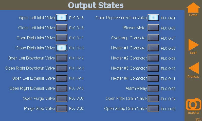
TWP/TWB201 – TWP/TWB7501

     Each elbow installed in the exhaust piping is equivalent to 10 feet of pipe. If the exhaust piping is vertical, a drip line
     must be installed to remove moisture. It is recommended to pipe the exhausts separately for ease of maintenance
     and troubleshooting.

     It is highly recommended to install bypass valves and piping around the dryer and filters to use during routine dryer
     maintenance.

                                                                  7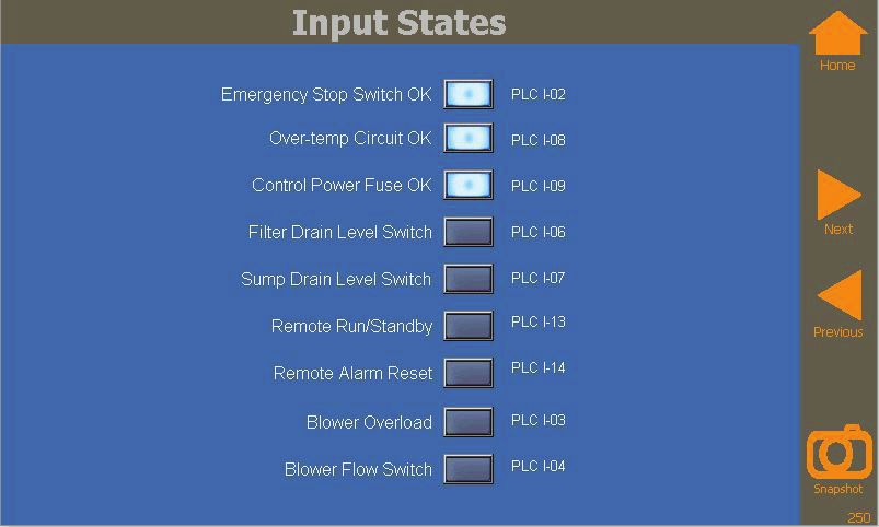
TWP/TWB201 – TWP/TWB7501

     GENERAL OPERATION
     The externally heated and blower purge desiccant dryers are designed to remove moisture in water vapor form, from
     compressed air to yield dewpoints of -40°F or better. The twin tower design allows constant drying of compressed
     air through one adsorption vessel while the other vessel desiccant bed regenerates by using heated dry purge air.

     Compressed air is directed through the inlet valve and up through the drying desiccant vessel where moisture is
     adsorbed by the desiccant. The low dewpoint dry air is then directed through the outlet check valve and down-
     stream for use.

     For externally heated dryers, regeneration of the saturated desiccant vessel bed is begun by blowing down the
     saturated vessel bed. The quick change from line pressure to atmosphere causes moisture to detach itself from the
     desiccant and be exhausted. The regeneration cycle is continued by directing 8% of the dry compressed air through
     a purge valve and orifice. The purge air is expanded to atmosphere, passed across an electric resistance heater
     where the air temperature is elevated to 400°F, then passed down through the saturated bed heating the desiccant.
     Adsorbed moisture is released from the desiccant, and then exits the dryer through the exhaust valve and muffler.
     Once heated regeneration is complete, the heater is powered off and cooling begins. Dry purge air continues to pass
     through the regenerated bed, cooling it to reduce the air temperature spike downstream and allow the newly regen-
     erated bed to readily adsorb moisture again after switchover.

     For blower purge dryers, regeneration of the saturated desiccant vessel bed is begun by blowing down the sat-
     urated vessel bed. The quick change from line pressure to atmosphere causes moisture to detach itself from the
     desiccant and be exhausted. The regeneration cycle is continued by the blower pulling in ambient air and passing
     this low pressure wet air across an electric resistance heater. The air temperature is elevated to 400°F, then passed
     down through the saturated bed, heating the desiccant. Adsorbed moisture is released from the desiccant, and then
     exits the dryer through the exhaust valve and muffler. Once heated regeneration is complete, the heater is powered
     off and cooling begins. The blower continues to pass air through the regenerated bed, cooling it to reduce the air
     temperature spike downstream and allow the newly regenerated bed to readily adsorb moisture again after switcho-
     ver. A stream of dry purge air in the amount of 2% may also be used after blower cooling to reduce the dewpoint
     spike at switchover caused by using wet ambient air with the blower.

     Once regeneration is completed, the offline desiccant vessel is slowly pressurized to system pressure. The dryer is
     ready for switchover, at which point compressed air will be directed though the newly regenerated desiccant bed for
     drying and the opposite desiccant vessel begins regeneration. This cycle continues automatically.

     The dryer inlet, exhaust, and repressurization valves are controlled by solenoid actuated control valves, which are
     controlled by the dryer PLC. The PLC operates opens and closes the valves using a programmed timing sequence.
     The PLC is equipped with various timing cycles to maximize the dryer efficiency. It is also possible to extend the
     drying cycle time using the dewpoint demand function.

                                                               8
TWP/TWB201 – TWP/TWB7501
TWP Desiccant Dryer Operation TWB Desiccant Dryer Operation
9TWP/TWB201 – TWP/TWB7501
FLOW SCHEMATIC MODELS TWP201-301
10TWP/TWB201 – TWP/TWB7501
FLOW SCHEMATIC MODELS TWP401-801
11TWP/TWB201 – TWP/TWB7501
FLOW SCHEMATIC MODELS TWP1001-1201
12TWP/TWB201 – TWP/TWB7501
FLOW SCHEMATIC MODELS TWP1501-7501
13TWP/TWB201 – TWP/TWB7501
FLOW SCHEMATIC MODELS TWB201-801
14TWP/TWB201 – TWP/TWB7501
FLOW SCHEMATIC MODELS TWB1001-1201
15TWP/TWB201 – TWP/TWB7501
FLOW SCHEMATIC MODELS TWB1501-7501
16TWP/TWB201 – TWP/TWB7501
TWP WIRING DIAGRAM STANDARD CONTROLLER
17TWP/TWB201 – TWP/TWB7501
TWP WIRING DIAGRAM STANDARD CONTROLLER
18TWP/TWB201 – TWP/TWB7501
TWP WIRING DIAGRAM STANDARD CONTROLLER
19TWP/TWB201 – TWP/TWB7501
TWP WIRING DIAGRAM STANDARD CONTROLLER
20TWP/TWB201 – TWP/TWB7501
TWB WIRING DIAGRAM STANDARD CONTROLLER
21TWP/TWB201 – TWP/TWB7501
TWB WIRING DIAGRAM STANDARD CONTROLLER
22TWP/TWB201 – TWP/TWB7501
TWB WIRING DIAGRAM STANDARD CONTROLLER
23TWP/TWB201 – TWP/TWB7501
TWB WIRING DIAGRAM STANDARD CONTROLLER
24
TWP/TWB201 – TWP/TWB7501
PANEL LAYOUT STANDARD CONTROLLER
25
TWP/TWB201 – TWP/TWB7501

     START UP

     Verify all piping and electrical connections are secure. Do not power the dryer at this time.

     Start the compressor and pressurize the air system, bypassing the dryer.

     Slowly pressurize the dryer by opening the inlet isolation valve. It is important to allow the dryer to slowly
     pressurize to prevent fluidization of the desiccant bed. Rapid pressurization can also cause damage to the
     vessel internal screens and filter elements.

     The dryer must be started without the mufflers installed. This will expedite removal of excess desiccant dust and
     prevent premature clogging of the mufflers.

     CAUTION: USE EAR AND EYE PROTECTION WHEN OPERATING THE DRYER WITHOUT MUFFLERS. EXCESSIVE
     NOISE WILL BE CREATED. DUST AND PARTICLES FROM THE SURROUNDING AREA MAY BECOME AIRBORNE.
     OPERATION WITHOUT MUFFLERS EXCEEDS OSHA LIMITS.

     Open the control air ball valve.

     Push in the emergency stop button.

     Power up the dryer. Check rotation of blower by pushing in contactor manually. If opposite of the flow direction
     arrow, switch the two leads.

     Pull the emergency button out.

     Start in Heatless - Touch the START IN HEATLESS OPERATION button from the controller’s SERVICE screen to
     start the dryer. The dryer will initially ensure that vessels are pressurized, then will begin by blowing down one
     of the vessels while placing the opposite ‘drying’ vessel online. If you do not want the dryer to begin cycling
     automatically, close the control air ball valve. This will prevent the inlet and exhaust valves from switching. In this
     situation, a bad blowdown alarm will occur which must be reset from the control panel after re-opening the control
     air ball valve.

     The dryer can be run in the heatless mode for two or three cycles to quickly remove desiccant dust caused by
     shipping or filling the unit. This also serves to verify that the vessels are switching normally, and to allow resolving
     any issues with system pressure before applying heat the regeneration process.

     Switch to Heated - When you are ready to switch the dryer to HEATED regeneration operation, simply touch the
     START IN HEATED OPERATION button from the controller’s Service screen. The dryer will immediately repressurize,
     then switch towers and start HEATED regeneration on the opposite vessel.

     Install the exhaust mufflers on the dryer.

     Check Purge Pressure - For TWP dryers, verify the purge pressure setting is correct for the operating conditions.
     The purge pressure setting must be set to the factory advised setting while using the dewpoint demand feature.
     The purge pressure must be set while in the Heated Regeneration State. Do not adjust the purge pressure when
     operating in the heatless backup timing configuration. Heater will shutoff if purge pressure is 10 psig or less. Heater
     will not turn on until purge pressure rises to 15 psig or greater.

     Heating - Verify that the heater contactor(s) pull in and the purge air temperature value on the controller screen
     begins to rise. If the dryer is blower type, then the blower will also be running at this time.

     Over-Temp - There is a redundant over-temperature module inside the control cabinet that is preset at the factory to
     650°F. This module monitors a thermocouple for purposes of independently sensing an over-temperature condition.
     In addition, there is an over-temp setting, also preset the factory to 650°F, accessed from the ADVANCED SETTINGS
     screen on the controller. This setting is associated with the purge temperature sensor.

                                                                26
TWP/TWB201 – TWP/TWB7501
It is not uncommon for the heater to shut down due to an over-temperature condition during initial startup of the
dryer. If this should happen, verify that the purge pressure setting agrees with the suggested setting and that there
is no backpressure in the regenerating tower (as would occur if a muffler was clogged or a check valve was not
functioning properly). If there is no sign of back pressure, then increase the overtemp adjustment on the over-temp
module, and the over-temp setting in the Advanced Setting screen by 50°F increments and reset the alarm. Repeat
until optimal overtemp settings are achieved. Consult factory if the dryer continues to shut down on over-temp at a
setting of 750°F or above.
Slowly open the dryer outlet isolation valve. Close the bypass valve. If applicable, tighten manway cover bolts. It is
common for the manway gasket to undergo additional compression on startup.
TIMING CONFIGURATION
The controller is designed for externally heated, blower purge and heatless backup cycle operation. The timing
configuration is pre-set at the factory for the specific dryer model. The default timing settings for each configuration
are listed below.
Externally Heated Cycle: 8 hours Blower Purge Cycle: 8 hours Heatless Backup Cycle: 14 min
Drying: 4 hours per tower. Drying: 4 hours per tower. Drying: 7 min per tower.
Heating: 2 hours 30 min per tower. Heating: 2 hours 30 min per tower. Purging: 6 min per tower.
Cooling/Purging: 1 hour 27 min per Cooling: 2 min per tower. Repressurization: 1 min per.
tower.
Purging: 85 min per tower.
Repressurization: 3 min per tower.
Repressurization: 3 min per tower.
The heating time is the maximum per tower per cycle. To save energy, the system is designed to end the heating
cycle and advance to cooling once the offline tower is fully regenerated. For blower purge models, the user may
disable the 2% cooling feature in order to prevent using dry purge air during regeneration. The cooling time will then
default to 25 min per tower per cycle.
Externally heated and blower purge dryers are both equipped with a heatless backup cycle as a standard feature.
This configuration may be selected by the user to use dry purge air for regeneration in place of heated air.
This operating cycle consumes 15-18% dry purge air and has a much shorter cycle time than the heated cycle.
Heatless backup can be used when there is an issue with the heated regeneration function of the dryer, but dry air is
still needed. The heatless backup cycle will allow the dryer to continue to produce dry air until a time when the dryer
can be shut down for service and maintenance. Heatless backup can also be used to more quickly purge a new
or oversaturated dryer. Once the dryer begins to achieve consistent dewpoint, the dryer can be switched back to
HEATED REGENERATION.
The dewpoint demand function is an energy savings feature that extends the drying cycle as long as the user
defined dewpoint requirements are met. The offline desiccant vessel completes its regeneration process as normal
and then waits in an idle state until the dewpoint degrade to the setpoint before switching over. By extending the
drying cycle, less purge air is consumed over a period of time. The Dewpoint Demand feature must be set to
ENABLED and the dewpoint sensor must be installed in the DEWPOINT SETTINGS screen.
27TWP/TWB201 – TWP/TWB7501
MANUAL STEPPING
This feature is used to assist in maintenance and troubleshooting of the dryer. Touching the STEP button at the
main screen will advance thru the regeneration states. This allows the user to skip ahead to desired stages of the
regeneration process more quickly. Using this feature may yield worse than desired dewpoints until the dryer is
allowed to cycle uninterrupted. For safety, when attempting to switch out of repressurization or blowdown, the dryer
will wait until the pressures in the tanks are at a safe level before proceeding to the next state.
CAUTION: Never step through the cooling state. Doing so may result in extreme temperatures being released
downstream. Only switch out of cooling if you are certain there is no possibility of releasing dangerous heat
downstream.
CONTROLLER DISPLAY & OPERATION
The dryer’s controller is an Allen-Bradley® PLC coupled with a proprietary color, touch panel HMI. The controller
is factory programmed with the proper timing configurations for the dryer model. The controller features user
configurable drain settings, timing configuration, dewpoint demand cycles, system pressure and temperature
monitoring, system alarms with user configurable settings and alarm log, and a manual stepping feature for
maintenance. Additionally, there is reference information for troubleshooting dryer operation and alarms.
The standard controller display is accessible at the front of the dryer without opening the enclosure. If the enclosure
must be opened, always remember to close and secure the enclosure door when not using!
28TWP/TWB201 – TWP/TWB7501
Main Screen User Controls
1. Menu Icon – Press to display the menu icons on the sides of the display.
2. Snapshot Icon – Press to save a snapshot of any screen to a flash drive.
3. Help Icon – Press to display online help screens where available.
4. Silence Button – Press to silence the alarm screen and turn off the alarm relay.
5. Alarm Reset Button – Press to reset all alarms and restart regeneration.
6. Enable Step Button – Press to enable the manual step function.
7. Step Button – Press to step to the next regeneration state – Use with caution.
8. Standby Button – Press to place the dryer in standby and to restart the dryer.
9. Log In / Log Out Buttons – Press to log in and log out as required
Supervisor default password is SUP (all caps).
These passwords may be changed, however, if the password is lost, the display must be completely reprogrammed
in order to reset, resulting in a potential service call!
Main Screen Information Display
a. Status Message Line –
Cycles thru one or more of the following, as well as, any active alarms.
PRESS START KEY WHEN READY
Displayed only before the dryer is started for the first time.
DRYER NOT CONFIGURED!
Displayed only before the dryer is configured for the first time.
ALL SYSTEMS OK
Default message – No alarms. Dryer is running in normal operation.
ALARM SHUTDOWN
Regeneration has shut down.
To restart, Press the Alarm Reset button.
LOW CONTROL AIR - REGENERATION SUSPENDED
Inlet air pressure is too low to provide sufficient control air for the dryer.
Regeneration is paused until air pressure returns.
MANUAL STEPPING ACTIVE
The Step button is active – Use with Care!
GOING TO STANDBY
Standby button has been touched and the dryer is waiting to go to standby
If heating, the dryer will cool for 2 minutes before going to Standby.
DRYER IN STANDBY - REGENERATION SUSPENDED
Dryer is in standby and will wait indefinitely until the Standby button has been
touched again.
29TWP/TWB201 – TWP/TWB7501
SWITCHING TO HEATLESS
The Switch To Heatless button has been touched from the Service Screen.
The dryer will immediately switch to cooling and completely cool the tower before
switching to Heatless.
SWITCHING TO HEATED
The Switch To Heated button has been touched from the Service Screen.
The dryer will immediately switch to Heated once the towers have repressurized.
RUNNING IN HEATLESS BACKUP
The dryer is running in Heatless Regeneration Mode.
DRYER IN POWER SAVER STATE
The Dewpoint is below the dewpoint demand set point at the end of the standard
drying time.
Dryer will wait until dewpoint rises above the set point before switching towers.
EXTENDED PURGING ACTIVE (Blower Models Only)
The 2% Cooling Setting is enabled in the Advanced Setting screen.
The dewpoint is below the dewpoint demand set point at the end of the
standard drying time.
The regenerating tower will continue to regenerate for the amount of time specified
in the Extended Drying Time setting (Typically 60 minutes), or until the dewpoint
rises above the dewpoint demand set point.
Not applicable if Dewpoint Demand is not installed and enabled.
Refer to the Alarms Section for a complete list of alarm messages which are also
displayed on this line.
a. State Message Line –
Displays the current regeneration state and the amount of time remaining in that state.
DRYER PARKED
The dryer has not yet been started. Once the dryer is started, it cannot be placed into
PARKED state without re-programming the PLC.
LEFT TOWER BLOWING DOWN / RIGHT TOWER BLOWING DOWN
Regenerating tower is waiting to depressurize before purging.
LEFT TOWER HEATING / RIGHT TOWER HEATING
Heated purge air is regenerating the tower before purging.
LEFT TOWER BLOWER COOLING / RIGHT TOWER BLOWER COOLING
(Blower Models Only).
Blower is cooling down the heater tube before switching to Cooling Regeneration.
BLOWER REGENERATION MODELS ONLY.
LEFT TOWER COOLING / RIGHT TOWER COOLING
Cool air is cooling down the tower.
If the dryer uses a blower and the Use 2% Purge Cooling setting is enabled, additional
purging also takes place during this state.
30TWP/TWB201 – TWP/TWB7501
LEFT TOWER EXTENDED PURGE / RIGHT TOWER EXTENDED PURGE
(Blower Models Only)
If the dryer uses a blower and the Use 2% Purge Cooling setting is enabled, and the
dewpoint is above the dewpoint demand setting, then the tower will continue to regenerate
using dry air until it times out, or the dewpoint rises above the demand set point.
LEFT TOWER REPRESSURIZING / RIGHT TOWER REPRESSURIZING
Regenerating tower is waiting to pressurize before switching towers.
RIGHT DRYING - TIME REMAINING / LEFT DRYING - TIME REMAINING
Dryer still has time remaining on the drying tower and is waiting for the time to expire
before switching towers.
SWITCHING TOWERS
Towers are switching.
REGENERATING LEFT TOWER / REGENERATING RIGHT TOWER (Heatless Mode)
Dryer is in heatless backup mode and regenerating the tower.
b. Sensor Values
Inlet Pressure and Temperature
Outlet Pressure
Pre-Filter Pressure
After-Filter Pressure
Outlet Temperature
Left and Right Tank Pressures
Left and Right Exhaust Temperatures
Purge Temperature
Purge Pressure (Dry Purge models only)
Dewpoint (Optional)
Flow Meter (Optional)
c. Time
d. Model and Serial Number
e. Active Dryer Graphic
31TWP/TWB201 – TWP/TWB7501
1. Heater Tube
Red when heater is active 7. 2% Purge Valve (Blower Purge ModelsOnly)
White – indicates valve(s) are open
2. Blower (Blower Purge Models Only) Yellow – indicates valves are closed
Green when blower is running,
Red during Blower related alarms 8. Repressurization Valve
White – indicates valve(s) are open
3. Blower Flow Switch (Blower Purge Models Only) Yellow – indicates valves are closed
Yellow – indicates lack of flow across flow switch
White – indicates lack of flow across flow switch 9. Outlet Check Valves (2)
Yellow – indicates flow across blower flow switch White – no air is flowing thru valve
Yellow – air is flowing thru valve
4. Exhaust Valves (2 or 4 depending on pre-exhaust)
White – indicates valve(s) are open 10. Purge Check Valves (2)
Yellow – indicates valves are closed White – no air is flowing thru valve
Yellow – air is flowing thru valve
5. Inlet Valves (2)
White – indicates valve(s) are open 11. Drain Valves (Optional)
Yellow – indicates valves are closed
6. Purge Stop Valve (Externally Heated Models Only)
White – indicates valve(s) are open
Yellow – indicates valves are closed
32TWP/TWB201 – TWP/TWB7501
1. Trending Icon – Press to access trending screens.
2. Alarms Icon – Press to access Active alarms and alarm history.
3. Sensors Icon – Press to display real-time sensor values, including user sensors.
4. I/O Screens Icon – Press to display the states of the PLC Inputs and Outputs.
5. Service Icons – Press for access to user and service related functions.
6. Support Icon – Press for access to dryer and support information.
7. Hide Menu Icon – Press to hide the menu icons.
8. Settings Icon – press to step thru the setting screens.
9. Page Left and Page Right Icons – Press to step thru the setting screens.
10. Snapshot Icon – Press to save a snapshot of any screen to the flash drive.
11. Help Icon – Press to display online help screens.
33TWP/TWB201 – TWP/TWB7501
Main Screen User Controls
Available for dryers which include a Dewpoint Demand sensor.
Drain Settings
Optional - Only applicable for dryers which control the drains using the PLC.
34TWP/TWB201 – TWP/TWB7501
User Sensor Settings
There are two 4-20 mA inputs on the PLC for the user.
If Sensor #1 is selected as a Flow Meter input, its value is displayed on the Main Display
Sensors #1 and #2 real-time values are accessed from the Sensor Screen.
Alarm Settings
35TWP/TWB201 – TWP/TWB7501
Advance Settings
Control Air Pressure
Regeneration will pause wen the inlet pressure drops 10 psi (68 kPa) below the settings.
Regeneration will resume when the pressure rises above the setting.
Purge Temperature
Maintains purge temperature is this level during heating.
Over-temp Temperature
Shuts down dryer if purge temperature sensor rises above this setting.
This is independent of external over-temp alarm.
Heat Exhaust Limit / Enable
Halts heating 5 minutes after exhaust temperature rises above setting.
Cool Exhaust Limit / Enable
Halts Cooling 5 minutes after exhaust temperature falls below setting.
Enable Shutdown Dryer on Bad Blow down
If this setting is enabled, the dryer will alarm and regeneration will shut down if the tower pressure is over 10 psi at
the end of the blow-down time.
If this setting is disabled, the dryer will wait indefinitely until the tower pressure drops below 10psi before proceeding
to regeneration.
36TWP/TWB201 – TWP/TWB7501
Enable Shutdown Dryer on Bad Repressurization
If this setting is enabled, the dryer will alarm and regeneration will shut down if the tower pressure is not within 10
psi of the inlet pressure at the end of the repressurization time.
If this setting is disabled, the dryer will wait indefinitely for the tower pressure to rise to within 10 psi of inlet pressure
before proceeding to regeneration.
Use 2% Purge Cooling (Blower Models Only). Enable to use dry purge air during cooling on blower units, otherwise,
ambient air will be used, which will result in higher dewpoint spikes after switching.
Factory Settings
These settings are only available to the Dryer Manufacturer’s Factory or Service Personnel and are included here for
reference only.
These settings are only available to the Dryer Manufacturer’s Factory or Service Personnel and are included here for
reference only.
37TWP/TWB201 – TWP/TWB7501
Historical Trend Display
There are 5 trend windows, each focusing on different data groups.
When you first enter a trend display, you must hit ZOOM ALL to zoom out to a usable window.
The screen is historical data only and will not automatically update as new data is logged. To refresh the data, you
must hit one of the zoom buttons.
Use RIGHT and LEFT ARROW keys to move between trend screens.
The following trends screens exist.
Dewpoint Dewpoint
Purge Temperature
Inlet Temperature
Outlet Temperature
System Pressure Inlet Pressure
Outlet Pressure
Left Pressure
Right Pressure
Purge Temperature Purge Temperature
Left Temperature
Right Temperature
Purge Pressure (Dry Purge Models Only)
38TWP/TWB201 – TWP/TWB7501
Exhaust Temperature Left Pressure
Right Pressure
Left Temperature
Right Temperature
Filter Pressure Inlet Filter Pressure
Outlet Filter Pressure
Inlet Pressure
Outlet Pressure
User Sensor Inputs Inlet Pressure
Dewpoint
User Sensor #1
User Sensor #2
Trend Elements
6 1 2
5
4
3
1. Time frame selection – select from 1 hr to 2 weeks.
2. Cursor line – drag or touch display to re-position.
3. Value box – data value at cursor position.
4. Scale – determined by the data type.
5. Time at cursor line – shows time at cursor line.
6. Current Time – system time.
39TWP/TWB201 – TWP/TWB7501
Export Data Sends data to the Flash Port in Excel readable format.
Clear Data Clear data log.
Page Right.
>> Move to latest available data.
Zoom In Zoom In one level, centered on the cursor.
Zoom Out Zoom Out one level, centered on cursor.
Zoom Reset Resets Zoom to 24 Hours.
Zoom All Zooms Out to 24 Hours.
Step Cursor Left Moves cursor left one unit (resolution unit).
Step Cursor Right Moves cursor right one unit (resolution unit).
Search Opens a search window where a date and time can be entered.
Note: Changing the time to a value that is prior to the latest logged value will suspend trend user interaction until the
clock catches up to and surpasses the latest logged value. This will result in loss of data and possible confusion. To
prevent data loss, the data can be exported before the clock is changed, then cleared after the clock is changed. All
logged data will be lost, however.
40TWP/TWB201 – TWP/TWB7501
Sensor Screen
Displays real time sensor values. This is the only place that the User Input 2 is displayed.
I / O Screens
Displays real time PLC inputs and Outputs for use in trouble shooting.
41TWP/TWB201 – TWP/TWB7501
Service Screen
42TWP/TWB201 – TWP/TWB7501
1. Heated and Heatless Operation Mode Buttons
Press to start dryer, or switch between heated and heatless mode.
When switching modes, you must wait for the mode transition to complete before
you can switch back.
2. Test Drains
Press to open the drain valve for the amount of time determined by Drain Duration setting.
3. Backup and Restore PLC Settings
Used to store a copy of the PLC settings so they can be transferred to a replacement PLC.
4. Reboot Display
Used to reboot the display panel should it be necessary.
An alternate method it to pull the orange plug on the back of the display panel.
5. Exit to System
Exits the application so that system level settings, such as communications
can be accessed.
6. Time/Date Set
Press to adjust the time and date.
See note in trending section for possible effects on data logging and trends.
7. Reference Guide
Press to access Reference Guide.
Use the onboard reference guide to learn about and troubleshoot dryer functions.
43TWP/TWB201 – TWP/TWB7501
Service Screen
Refer to this screen for contact and machine information.
Only users with Factory or Service level access can change this information.
Alarm Indicator Display
Indicators will display in RED for all active alarms.
Pressing the indicator will display troubleshooting information relating to the alarm.
44TWP/TWB201 – TWP/TWB7501
Alarm History
Displays a log of all alarm and event activity since the last time the history log was cleared.
User Buttons
Page Up / Down – Move up and down thru menu.
Clear History – Clears the alarm history (use with caution).
Save to File – Save history to Excel readable file on flash drive.
45TWP/TWB201 – TWP/TWB7501
Active Alarms List Screen
Displays all active alarms.
Pressing Alarm Reset Button will reset all active alarms and automatically restart the dryer.
Alarm Relay
There is an alarm contact on the PLC for driving external alarm devices or for feeding into a PLC.
The alarm relay turns on whenever there is a new alarm and turns off when the alarm silence or alarm reset button is
pressed.
Alarm Reset
Clears all alarms and restarts regeneration.
46Alarm Description Settings Notes
TOWER FAILED TO BLOWDOWN Alarms if regenerating tower Is not above 10 psi at the end of blowdown. Default is 60 seconds Shuts down regeneration (settable)
Adjustable from 15 to 300 seconds Manual reset
TOWER FAILED TO PRESSURIZE Alarms if regenerating tower Is not within 10 psi of the drying tower pressure when Always enabled Shuts down regeneration
attempting to switch towers. Manual reset
ALARM CHART
SWITCHING FAILURE Alarm occurs whenever the pressure drop across the inlet valve (including the filter) rises Always enabled Manual reset
above 15psi (10kPa) for 2 seconds Does not shutdown regeneration. Inlet will not open under high diff. pressure
HIGH PURGE TEMPERATURE Alarms if the purge temperature rises above the high purge temperature set point. Default is 650ºF (343ºC), Always enabled The heater is inactive until the alarm is manually reset.
Adjustable from 200ºF to 800ºF (90ºC to 425ºC) This alarm does not shutdown regeneration.
TWP/TWB201 – TWP/TWB7501
HIGH OVER TEMPERATURE Alarms if the alarm contact from the external over-temp monitor are closed. Default is 650 ºF, Always enabled The heater is inactive until the alarm is manually reset.
Adjustable from module This alarm does not shutdown regeneration.
LOW PURGE TEMPERATURE Alarms if the purge temperature does not rise above 150 F within 15 minutes after the Fixed at 150ºF (65ºC) The heater is inactive until the alarm is manually reset.
heater turns on. Always enabled This alarm does not shutdown regeneration.
CLOGGED MUFFLER Alarms if the pressure in the regenerating tower is above 5 psi for 5 minutes Fixed at 5 psi (34 kPa) Automatically resets after pressure falls below setting
Always Enabled
LOW PURGE PRESSURE Alarms if the purge pressure is below the set point for 10 seconds during regeneration Default is 25 psi (170 kPa), Always enabled Automatically resets after pressure rises above setting
(models wihout blowers only) Adjustable from 0 to 100 psi ( 0 to 650 kPa)
HIGH INLET TEMPERATURE Alarm results when Inlet temperature is above 101 F Default is 101ºF (38ºC), Always enabled Automatically resets when the temperature falls below the set point
Adjustable from 0ºF to 200ºF (0ºC to 90ºC)
LOW INLET PRESSURE User settable alarm results when Inlet pressure is below 60 psi for 5 minutes Default is 60 psi (414 kPa), User Enabled Automatically resets when the pressure rises above the set point
Adjustable from 0 to 200 psi ( 0 to 1300 kPa)
HIGH DEW POINT Alarms if the dew-point is above the set point for 45 minutes Default is -20ºF (-28ºC), User Enabled Automatically resets when the dew point rises above the set point
Adjustable from -250ºF to 75ºF ( -150ºC to 20ºC)
CLOGGED PRE-FILTER Difference between inlet pressure and drying tower pressure is greater than 8 psi for 5 Default is 8 psi (55 kPa), User Enabled Automatically resets when the pressure drops below the set point
minutes Adjustable from 0 to 15 psi ( 0 to 100 kPa)
CLOGGED AFTER-FILTER Difference between outlet pressure and drying tower pressure is greater than 8 psi for 5 Default is 8 psi (55 kPa), User Enabled Automatically resets when the pressure drops below the set point
minutes Adjustable from 0 to 15 psi ( 0 to 100 kPa)
BLOWER OVERLOAD ALARM Blower overload contact has opened while the blower is running. Blower FLA adjustment on device Manual reset to restart the dryer
47
(models with blowers only)
BLOWER FLOW ALARM Flow switch does not agree with blower output for 30 seconds. none Manual reset to restart the dryer
(models with blowers only
DRAIN FAULT Drain switch Input is closed for 5 seconds longer than Duration setting Use Drain Duration setting Automatically resets once the switch returns to normal
LOW AUX SENSOR Alarms when input falls below setpoint Default is 0, User Enabled Automatically reset when value rises above setpoint
Adjustable from -32767 to 32768
HIGH AUX SENSOR Alarms when input rises above setpoint Default is 0, User Enabled Automatically reset when value drops below setpoint
Adjustable from -32767 to 32768
LOSS OF CONTROL POWER Alarms if there is no voltage on the output of the control fuse. none Must be manually reset by the operator
LOSS OF SENSOR POWER Alarms if all pressures sensors register a fault. none Must be manually reset by the operator
EMERGENCY STOP Emergency Stop button has been pressed. none
INLET, or TANK PRESSURE SENSOR Sensor input is open or shorted to ground or V+ none Shuts down regeneration
FAULT Must be manually reset by the operator
OUTLET or PURGE PRESSURE SENSOR Sensor input is open or shorted to ground or V+ none Must be manually reset by the operator
FAULT
DEWPOINT SENSOR FAULT Sensor input is open or shorted to ground or V+ none Automatically reset once the fault condition clears
AUX SENSOR FAULT Sensor input is open or shorted to ground or V+ none Automatically reset once the fault condition clears
TEMPERATURE SENSOR FAULT Alarms if there is a break in the type J thermocouple sensor none Must be manually reset by the operatorTWP/TWB201 – TWP/TWB7501
COMMUNICATIONS
WARNING! - DO NOT ATTEMPT TO CHANGE SETTINGS OR OTHERWISE OPERATE THE DRYER REMOTELY
WITHOUT A FIRM UNDERSTANDING OF DRYER OPERATION. IMPROPER SETTINGS OR CONTROL MAY
RESULT IN DAMAGE TO DRYER COMPONENTS OR PHYSICAL INJURY.
The user’s panel includes an Ethernet and a Serial port which can be used for Modbus communications. The Ether-
net port can be used to access Modbus/TCP registers, as well as, the internal VNC servers across multiple dryers.
The Serial port can access Modbus RTU registers on a single dryer using either RS232 or RS422/485
hardware protocol.
VNC Server
The internal VNC server runs in the back ground by default. Any VNC Client may be used to access the dryer’s VNC
server via port 5900.
Excessive network traffic or network interference may cause the VNC server to intermittently shut down. Rebooting
the HMI via the Service menu or via Modbus register 40101 will restore the VNC Server after reboot.
Ethernet
The Ethernet port is pre-configured to acquire its network IP address and configuration from the network’s DHCP
server. Proper cabling and isolation techniques are required to prevent electrical noise from entering the system
through this port. Contact your local electrical parts distributer for assistance.
Serial Modbus Port
The serial port is located along the bottom edge of the HMI. This port supports full RS232, RS422, and RS485 hard-
ware protocols. This port is NOT isolated. Proper cabling and isolation techniques are required to prevent electrical
noise from entering the system through this port. Contact your local electrical parts distributer for assistance.
DB25 Female Connector DB25 Female Connector
Communication Settings
DWG# ATE11605 Rev -
48TWP/TWB201 – TWP/TWB7501
Pin Number Signal Signal Name Signal Direction Type
1 FG Frame Ground - -
2 TD Transmit Data Output RS232C
3 RD Receive Data Input RS232C
4 RTS Request to Send Output RS232C
5 CTS Clear to Send Input RS232C
6 DSR Data Set Ready Input RS232C
7 SG Signal Ground - 5V-/RS232C
8 DCD Data Carrier Detect Output RS232C
9 - - - -
10 - - - -
11 - - - -
12 TXDA Transmit Data Output RS422/RS485
13 TXDB Transmit Data Output RS422/RS485
14 RTSA Request to Send Output RS422
15 RTSB Request to Send Output RS422
16 - - - -
17 - - - -
18 CTSA Clear to Send Input RS422
19 CTSB Clear to Send Input RS422
20 DTR Data Terminal Ready Output RS232C
21 5V+ 5 V Power Supply + Output -
22 RI Ring Indicator Input RS232C
23 - - - -
24 RXDA Receive Data Input RS422
25 RXDB Receive Data Input RS422
DB25 Connector Pin-out
Notes: Settings are not checked for proper range. Bounds checking must be done in the controlling computer.
Setting a register outside of its stated range may result in unpredictable dryer operation.
49TWP/TWB201 – TWP/TWB7501
MODBUS REGISTER MAP
Address R/W Description Notes
10001 R Status - Heated Mode Running in Heated mode
10002 R Status - Heatless Mode Running in Heatless mode
10003 R Status - Switching to Heated Switching from Heatless to Heated
10004 R Status - Switching to Heatless Switching from Heated to Heatless
10005 R Status - Extended Drying Active Variable drying time conditions met
10006 R Status - Extended Dry Purge Active Currently using extended dry purge
10007 R Status - Stepping Allowed Stepping is currently Allowed
10008 R Status - Manual Stepping Active Manual stepping is currently enabled
10009 R Status - Run/Stop Status Drying is currently running
10010 R Status - Dryer is Parked Dryer is in Standby
10011 R Status - Heating Exhaust Limits Met Heating exhaust conditions have been met
10012 R Status - Cooling Exhaust Limits Met Cooling exhaust conditions have been met
10013 R Status - Shutdown Currently shutdown due to alarm
10014 R Status - Active alarm There are current active alarms
10015 R Status - Control Air Control Air pressure is above its setting
10016 R Status - Restarting Dryer Dryer is currently restarting after an alarm
10017 R Status - Repressurizing Currently the dryer is repressurizing both tanks
10018 R Status - Regenerating Currently the dryer is regenerating in Heatless operation
10019 R Status - Heating Currently regenerating using heated air
10020 R Status - Blower Cooling Currently operating in the heating stage of regeneration
10021 R Status - Ambient (Blower) Cooling Currently using blower to provide ambient air for cooling
10022 R Status - Stripping Currently using dry purge air for cooling
10023 R Status - Drying Side 0 = Left Tower Drying
1 = Right Tower Drying
10024 R Status - Regeneration Side 1 = Left Tower Regenerating
0 = Right Tower Regenerating
10025 R Status - Blowing Down Regenerating tower is currently blowing down
10026 R Status - Remote Shutdown Remotely shutdown the dryer
10027 R Status - Remote Standby Remotely place the dryer in Standby
10028 R Status - OK to Switch Tank pressures are ok to switch towers or open exhaust valves
10033 R Output - Alarm Relay Relay is active
10034 R Output - Repressurization Valve Repressurization valve is open
10035 R Output - Purge Stop Valve Purge stop valve is closed
(Blower Models Only)
10036 R Output - Dry Purge Valve Dry Purge valve is open (Externally Heated Models Only)
10037 R Output - Drain #1 Valve Drain valve is open
10038 R Output - Drain #2 Valve Drain valve is open
10039 R Output - Blower Contactor Blower is running (Blower Models Only)
10040 R Output - Purge Heater Contactor Heater is active
10041 R Output - Over Temp Contactor Over-temp contactor is closed allowing heating
10042 R Output - Purge Heater Contactor Bank 2 Heater Bank #2 is active (Only dryers with Multi-Bank Heaters)
10043 R Output - Purge Heater Contactor Bank 3 Heater Bank #3 is active (Only dryers with Multi-Bank Heaters)
10044 R Output - Purge Heater Contactor Bank 4 Heater Bank #4 is active (Only dryers with Multi-Bank Heaters)
10045 R Output - Left Pre-Exhaust Valve Left pre-exhaust valve is open
(Only dryers with pre-exhaust valves)
50TWP/TWB201 – TWP/TWB7501
MODBUS REGISTER MAP (CONT’D)
Address R/W Description Notes
10046 R Output - Right Pre-Exhaust Valve Right pre-exhaust valve is open
(Only dryers with pre-exhaust valves)
10047 R Output - Left Exhaust Valve Left Exhaust valve is open
10048 R Output - Right Exhaust Valve Right Exhaust valve is open
10049 R Output - Open Left Inlet Valve Left Inlet Valve is open (Dual acting Inlet valves only)
10050 R Output - Open Right Inlet Valve Right Inlet Valve is open (Dual acting Inlet valves only)
10051 R Output - Close Left Inlet Valve Left Inlet Valve is Closed
10052 R Output - Close Right Inlet Valve Right Inlet Valve is Closed
10066 R Input - Sensor Power Sense 1 = sensor power present
0 = blown fuse or missing power
10067 R Input - Emergency Stop Switch 1 = Normal switch position (No Emergency Stop )
0 = Emergency Stop Pressed
10068 R Input - Blower Overload 1 = Blower Overload (Blower Models only)
10069 R Input - Blower Flow Switch 1 = Blower Flow Switch Closed (Active) (Blower Models only)
10071 R Input - Drain Switch #1 1 = drain switch closed (Demand drains only)
10072 R Input - Drain Switch #2 1 = drain switch closed (Demand drains only)
10073 R Input - Over-temp Sense 1 = Over-temp module normal operation
0 = Over-temp module has tripped on high temperature.
Heaters are disabled
10074 R Input - Output Power Sense 1 = Output power is present,
0 = Blown fuse or missing power
10078 R Input - Run/Stop Switch 1 = External Run/Standby Switch set to Standby Position
10079 R Input - Remote Alarm Reset 1 = External contact closure resets Alarms and Restart Dryer
10081 R Alarm - Left Blowdown see separate alarm chart for details
10082 R Alarm - Right Blowdown see separate alarm chart for details
10083 R Alarm - Left Repressurization see separate alarm chart for details
10084 R Alarm - Right Repressurization see separate alarm chart for details
10085 R Alarm - High Purge Temperature see separate alarm chart for details
10086 R Alarm - Low Purge Temperature see separate alarm chart for details
10087 R Alarm - High Over Temperature see separate alarm chart for details
10089 R Alarm - Left Muffler see separate alarm chart for details
10090 R Alarm - Right Muffler see separate alarm chart for details
10091 R Alarm - Low Purge Pressure see separate alarm chart for details
10092 R Alarm - Inlet Temperature see separate alarm chart for details
10093 R Alarm - Inlet Pressure see separate alarm chart for details
10094 R Alarm - High Dewpoint see separate alarm chart for details
10095 R Alarm - Pre-filter see separate alarm chart for details
10096 R Alarm - After-filter see separate alarm chart for details
10097 R Alarm - Blower Motor Overload see separate alarm chart for details
10100 R Alarm - Blower Flow Switch see separate alarm chart for details
10101 R Alarm - Drain #1 Switch see separate alarm chart for details
10102 R Alarm - Drain #2 Switch see separate alarm chart for details
10103 R Alarm - Aux Sensor Input #1 Low see separate alarm chart for details
10104 R Alarm - Aux Sensor Input #1 High see separate alarm chart for details
51You can also read