F4F Wildcat BNF/PNP - Instruction Manual Bedienungsanleitung Manuel d'utilisation Manuale
←
→
Page content transcription
If your browser does not render page correctly, please read the page content below
F4F Wildcat BNF/PNP

Instruction Manual
Bedienungsanleitung
Manuel d’utilisation
Manuale
EN

                                                                   NOTICE
       All instructions, warranties and other collateral documents are subject to change at the sole discretion of Horizon Hobby, Inc.
       For up-to-date product literature, visit http://www.horizonhobby.com and click on the support tab for this product.

                                                        Meaning of Special Language:
       The following terms are used throughout the product literature to indicate various levels of potential harm when
       operating this product:
       NOTICE: Procedures, which if not properly followed, create a possibility of physical property damage AND little or
       no possibility of injury.
       CAUTION: Procedures, which if not properly followed, create the probability of physical property damage AND a
       possibility of serious injury.
       WARNING: Procedures, which if not properly followed, create the probability of property damage, collateral damage,
       and serious injury OR create a high probability of superficial injury.

         WARNING: Read the ENTIRE instruction manual to become familiar with the features of the product before operating. Failure
     to operate the product correctly can result in damage to the product, personal property and cause serious injury.
     This is a sophisticated hobby product and NOT a toy. It must be operated with caution and common sense and requires some
     basic mechanical ability. Failure to operate this Product in a safe and responsible manner could result in injury or damage to
     the product or other property. This product is not intended for use by children without direct adult supervision. Do not attempt
     disassemble, use with incompatible components or augment product in any way without the approval of Horizon Hobby, Inc.
     This manual contains instructions for safety, operation and maintenance. It is essential to read and follow all the instructions and
     warnings in the manual, prior to assembly, setup or use, in order to operate correctly and avoid damage or serious injury.

 Safety Precautions and Warnings
 As the user of this product, you are solely responsible for               • Moisture causes damage to electronics. Avoid water
 operating in a manner that does not endanger yourself and                   exposure to all equipment not specifically designed and
 others or result in damage to the product or the property of                protected for this purpose.
 others.                                                                   • Never lick or place any portion of your model in your
                                                                             mouth as it could cause serious injury or even death.
 This model is controlled by a radio signal subject to interference
 from many sources outside your control. This interference can
 cause momentary loss of control so it is advisable to always
 keep a safe distance in all directions around your model, as this         Battery Warnings and Guidelines
 margin will help avoid collisions or injury.                              The Battery Charger included with the F4F Wildcat BNF has
                                                                           been designed to safely charge the Li-Po battery. You must
      Age Recommendation: 14 years or over. This is                        read the following safety instructions and warnings before
      not a toy. This product is not intended for use by children          handling, charging or using the Li-Po battery.
      without direct adult supervision.
      •    Never operate your model with low transmitter
          batteries.                                                         CAUTION: Li-Po batteries are significantly more volatile
                                                                         than the alkaline, Ni-Cd or Ni-MH batteries used in RC
      • Always operate your model in an open area away from
                                                                         applications. All instructions and warnings must be
        cars, traffic or people.
                                                                         followed exactly. Mishandling of Li-Po batteries can result
      • Avoid operating your model in the street where injury or         in a fire, personal injury, and/or property damage.
        damage can occur.
      • Never operate the model in the street or in populated              • By handling, charging or using the included Li-Po battery
        areas for any reason.                                                you assume all risks associated with lithium batteries.
                                                                             If you do not agree with these conditions, return your
      • Carefully follow the directions and warnings for this and
                                                                             complete F4F Wildcat model in new, unused condition
        any optional support equipment (chargers, rechargeable
                                                                             to the place of purchase immediately.
        battery packs, etc.) you use.
                                                                           • You must charge the included Li-Po battery in a safe area
      • Keep all chemicals, small parts and anything electrical
                                                                              away from flammable materials.
        out of the reach of children.

      2
EN
F4F Wildcat PNP/BNF Instruction Manual
From Pearl Harbor through 1942 the F4F Wildcat was the only
WARNING: Although your aircraft comes almost ready to
U.S. fighter in the Pacific theater capable of thwarting the
advances of Japan’s naval air forces. And though it was slower fly, it is for experienced RC pilots only and is not a toy. Misuse
and less maneuverable than the vaunted Zero, its heavier of the plane can cause serious bodily harm and damage to
armor, self-sealing fuel tanks and rugged airframe could often property. Therefore, only an experienced RC pilot should fly
help a skilled pilot overcome this performance gap and live to it. Because of the high performance nature of this aircraft,
fight another day. we recommend you only fly in very large open areas or RC
club fields.
ParkZone brings the legendary Wildcat to life with this great
flying Bind-N-Fly® park flyer modeled after a plane flown by
Lieutenant Commander Edward “Butch” O’Hare – the U.S. Navy’s
first flying ace. Scale touches include a realistic paint scheme,
simulated engine cylinders and cowl flaps, molded wheels
tucked into the fuselage and more.
Table of Contents F4F Wildcat Features
Bind-N-Fly Plug-N-Play
Topic Page Version Version
Safety Precautions and Warnings 2 Motor
Introduction
Battery Warnings
3
4
ParkZone 480-size 960Kv
brushless outrunner
Charging the Flight Battery 4 ESC
General Assembly and Maintenance Tips
Transmitter and Receiver Binding
5
6
ParkZone 18A brushless
Installing Wings 7 Receiver
Installing Horizontal Tail and Pushrods on Control Horns 8
Spektrum™ AR500 DSM2
5-channel sport receiver *
Installing Flight Battery 9
Battery
Adjusting Center of Gravity
Control Direction Test
9
10 3S 11.1V 1300mAh 15C Li-Po
Reverse Controls 10 Charger
Control Surface Travel Measurement 11 Variable rate 2- to 3-cell
Li-Po balancing fast charger
Installing the Propeller 12
Motor and ESC Removal 13 Transmitter
PNP Installation 14 Full range DSM2
Range Check 14 aircraft transmitter *
Before Each Flying Session 15 * Recommended for Plug-N-Play Version
Flying Tips 15
Repairs 15
Low Voltage Cutoff (LVC) 15
Troubleshooting Guide 16
F4F Wildcat Specifications
Replacement Parts and Optional Parts 16
Warranty and Service 17 Wingspan 38.4 in (975mm)
Contact Information 18 Length 28.7 in (730mm)
Weight (RTF) 25.4 oz (720 g)
To register your product online, go to http://www.parkzone.com
3EN
®
ONLY
Battery Warnings
• Never charge the battery discontinue charging or discharging immediately. Quickly and
unattended. When charging the safely disconnect the battery. Continuing to charge or discharge
battery you should always remain a battery that has begun to balloon or swell can result in a fire.
in constant observation to monitor
• Store the battery at room temperature in a dry area for best
the charging process and react to
Never leave Always charge
results.
charging Batteries
unattended.
Batteries away from
flammable materials.
potential problems that may occur.
• When transporting or temporarily storing the battery the
• After flight, the battery must be cooled to ambient temperature
temperature range should be from 40–120º F (4–49º C). Do not
before charging.
store battery or model in a car or direct sunlight. If stored in a
• DO NOT USE A NiCd OR NiMH CHARGER. Failure to charge the hot car, the battery can be damaged or even catch fire.
battery with a compatible charger may cause fire resulting in
• Do not over-discharge the Li-Po flight battery. Discharging
personal injury and/or property damage.
the battery too low can cause damage to the battery resulting
• It is not recommended to “top-off” a fully charged or near in reduced power, duration or failure of the battery. (See details
fully charged Li-Po battery. Attempting to do so may cause the below).
charger to overcharge the battery, resulting in damage to the
• Li-Po cells should not be discharged to below 3V each under
battery and possible fire. If the voltage of each cell within the
load.
battery is approximately 4.1V or higher, it is best to discharge
the battery for at least a short time before attempting to charge • Never leave the Li-Po battery plugged in to the airplane after
it. Do not charge a 3S (11.1V nominal) battery if it is at or above completing a flight. The battery must be disconnected before
12.3V Li-Po cells should NEVER be charged to more than 4.2V. powering off the transmitter after every flight.
Any cell that is charged to a voltage higher than 4.2V may be
In the case of the Li-Po battery used for the F4F Wildcat, you will
damaged and could catch fire
not want to allow the battery to fall below 3V per cell during
• If at any time the battery begins to balloon or swell, flight.
Charging the Flight Battery
The charger included with your F4F Wildcat uses unique circuitry from a wall outlet. Please note that some 12V outlets require
that ensures an accurate charge every time and protects your your vehicle to be running for the outlet to be operational.
Lithium Polymer battery from the dangers of overcharging. This The LED will continually blink while the battery charges. It is
charger continually monitors the battery and automatically not recommended to charge batteries while the vehicle is in
stops charging when the battery is fully charged. motion.
DC Li-Po Balancing Charger Features 4. Charging is finished when the LED indicator glows steadily.
• Charges 3-cell lithium polymer battery packs at 1-amp
• LED charge status indicator
• 12V accessory outlet input cord—you must charge the included
Li-Po battery pack with a Li-Po specific charger only (such as the
included charger).
1. The 12V DC 3S Li-Po balancing charger provides a charge
current of 1 amp. The typical charge time for the included 11.1V
1300mAh Li-Po is approximately 1 hour.
2. Locate the safety charge lead on the battery pack. Connect
the battery pack to the charger. Charge through the balance
lead on the battery pack. The blue EC3™ connector will remain WARNING: Failure to use the proper charger for a Li-Po
disconnected when using the included charger. battery can result in serious damage, and if left charging
3. Connect the charger to a 12V power outlet in a vehicle long enough, will cause a fire. ALWAYS use caution when
or purchase the AC adapter (HBZ1004) to allow charging charging Li-Po batteries.
4EN
General Assembly and Maintenance Tips
Note: This checklist is not a replacement for the content included in this manual. Although it can be used as a quick start guide, you
should read the entire manual before proceeding.
First Flight Preparation
Activity PNP BNF
Remove and inspect contents u u
Begin charging flight battery u u
Assemble F4F Wildcat u u
Install receiver u
Install fully charged battery u u
Bind the receiver to a transmitter, if applicable u u
Perform the Control Direction Test with the transmitter u u
Adjust flight controls and transmitter u u
Perform a radio system Range Check u u
Find a safe and open flying field u u
Plan flight for flying field conditions u u
Maintenance After Flying
Activity PNP BNF
Disconnect flight battery from ESC (Required for Safety) u u
Turn off transmitter (Required for Safety) u u
Remove flight battery from aircraft u u
Recharge flight battery u u
Clean aircraft (wipe off dirt, etc.) u u
Repair or replace all damaged parts u u
Carefully disassemble and store aircraft u u
Store flight battery apart from aircraft and monitor the battery charge u u
Make note of flight conditions and flight plan results, planning for future flights u u
5EN
Transmitter and Receiver Binding
Binding is connecting a transmitter to an aircraft receiver wirelessly or electronically so the aircraft receiver recognizes the
transmitter GUID (Globally Unique Identifier) code. Binding is necessary for proper operation.
The F4F Wildcat requires a DSM2 full range (high power) transmitter. The list below is Spektrum™ or JR® DSM2-equipped full range
transmitters and modules that can bind to the F4F Wildcat’s receiver:
•Spektrum DX5e •Spektrum DX6i •Spektrum DX7/DX7se •JR X9303/9503 2.4 •JR 11X •JR 12X 2.4 •All SPM Module systems
List is complete as of this printing. Additional compatible transmitters may be available.
Note: When using a Futaba transmitter with a Spektrum receiver, reversing the throttle channel may be required.
CAUTION: ALWAYS power on the transmitter before connecting the flight battery to the aircraft ESC. ALWAYS
disconnect the flight battery from the aircraft ESC before powering off the transmitter.
Additional Binding Information
Before each flight, power on the transmitter and wait about five (5) seconds
before connecting the flight battery to the aircraft ESC. The transmitter
scans and secures two radio frequencies for aircraft control. When the flight
battery is connected too quickly for the transmitter to make frequency
selection, the transmitter and receiver may not connect. When there is no
connection, leave the transmitter powered on, disconnect the flight battery
then connect the
flight battery to
the receiver.
Binding Procedure Reference Table
1. Read transmitter instructions for binding to a receiver (location of transmitter’s Bind control).
2. Make sure transmitter is powered off.
3. Install a bind plug in the receiver Batt/Bind port (if required and not already installed from the
factory).
4. Connect the flight battery to the ESC. The receiver LED will begin to flash rapidly.
5. Move the transmitter controls to neutral (flight controls: rudder, elevators and ailerons) or to low
positions (throttle, throttle trim, and flight control trims).*
6. Power on the transmitter while holding the transmitter bind button or switch. Refer to your
transmitter’s manual for binding button or switch instructions.
7. The receiver light will go from flashing rapidly to flashing slowly. After 5–10 seconds the light will
become solid indicating the receiver is bound to the transmitter.
8. Remove the bind plug from the receiver.
9. Safely store the bind plug (some owners attach the bind plug to their transmitter using two-part loops
and clips).
10. The receiver should keep the binding to the transmitter until a bind plug is put in the receiver Batt/
Bind port.
* The throttle will not arm if the transmitter’s throttle control is not put at the lowest position.
If you encouner problems, obey binding instructions and refer to transmitter troubleshooting guide for
other instructions. If needed, contact the appropriate Horizon Product Support office.
6EN
Installing Wings
1. Put the wing tube in the round hole in the wing slot of the 4. Fully install right wing in fuselage using screw.
fuselage.
5. Install the left wing using the steps above.
2. Put right wing on the wing tube.
6. Attach the two (2) aileron connectors to the aileron Y-harness
in the fuselage.
3. Move the wing on the tube into the slot in the fuselage while
putting the aileron control connector in the fuselage.
Note: There is no difference between the two connections on
the Y-harness. Left and right servo lead connectors do not have
to be connected to a particular side of the Y-harness.
7EN
Installing Horizontal Tail and Pushrods
on Control Horns
Installing the Horizontal Tail 4. Install the left horizontal tail (control horn is attached to
bottom of left panel) using the steps above, while connecting
1. Install horizontal tail tube through hole in fuselage. the elevator joiner of the left and right horizontal tails.
2. Install right horizontal tail on tube on right side of fuselage.
5. Apply four (4) pieces of tape to horizontal tail sections and
top and bottom of fuselage.
Note: Removing tape will remove paint from painted parts.
3. Attach right horizontal tail to fuselage.
8EN
Installing Flight Battery and Center of Gravity
Installing the Flight Battery
Note: After centering control surfaces with Control Direction
Test (pg 12) and before flying, rebind the aircraftt so the control
surfaces are neutral when plugging in the flight battery.
Note: If using a 1800–2200mAh LiPo pack rather than the 1300
mAh LiPo supplied with the Wildcat, a longer hook and loop
strap is supplied
CAUTION: Install receiver and connect the speed
control into the throttle channel (for PNP) before installing
the flight battery.
Note: Always power on transmitter before connecting battery.
1. Install the flight battery (PKZ1033) in the fuselage pocket in 3. Secure the flight battery using the hook and loop straps.
the front of the fuselage.
4. Make sure wires in the fuselage do not block the canopy
hatch when closing the hatch.
2. Connect the battery to the ESC.
Center of Gravity (CG)
The CG location is 17/8 in (47 mm) back from leading edge of the
wing at the root +/- 1/8 inch (3mm). This CG location has been
determined with the ParkZone 11.1V 1300mAh Li-Po battery
installed in the battery cavity.
9EN
Control Direction Test and Reverse Controls
Note: This Control Direction Test does not describe Mode 1 or 5. When the transmitter rudder stick is pushed to the left, the
Mode 2 transmitter control assignment. Refer to transmitter rudder should move to the left.
instructions for information about Mode 1 and Mode 2 control
assignment.
Complete aircraft and transmitter bind before doing these tests.
Move the transmitter controls to make sure aircraft control sur-
faces move correctly.
Note: When using a DSM 2 transmitter, rudder, aileron and elevator
will have to be reversed on the transmitter prior to flight
1. When the transmitter elevator stick is pushed forward, the
elevator should move down.
6. When the transmitter rudder stick is pushed to the right
the rudder should move to the right (viewed from behind the
aircraft).
2. When the transmitter elevator stick is pulled back, the elevator
should move up.
Controls in Reverse in Control Direction Test
3. When the transmitter aileron stick is pushed to the left, the If controls respond in the opposite direction from the description
left aileron should move up and the right aileron should move in the Control Direction Test, you may reverse/change the
down. direction for operation of flight controls. Refer to Servo Reversing
in your transmitter’s instructions for changing direction of
transmitter flight controls.
4. When the transmitter aileron stick is pushed right, the right
aileron should move up and the left aileron should move
down.
10EN
Control Surface Travel Measurement
Control Surface Travel Information Aileron
Note: Measurements are made at the widest point of each
control surface from the neutral position for each control
surface.
Note: These settings have a tolerance of plus or minus 1mm.
Factory Setting for Control Surface Travel
Factory settings for the DX5e transmitter are Dual rates set at
100% on high rate and at 70% on low rate. These dual rates High Rate: 11 mm
cannot be changed on the DX5e. All controls surfaces are set
for 100% adjustable travel volume (ATV). Low Rate: 8 mm
The factory settings provide a moderate amount of control Neutral: 0 mm
surface movement. The pushrods come installed in the
outermost holes of the servo arms. Clevises come installed in
the outermost holes of the control horns (away from the control
surface).
Elevator
High Rate: 13 mm
Low Rate: 9 mm
Neutral: 0 mm
Rudder
Low Rate: 11 mm
High Rate: 14 mm
Neutral: 0 mm
Factory Setting for Rudder and Elevator
Servo Arms and Pushrods
11EN
Installing the Propeller
Note: The information on this page is for maintenance of the F4F 3. Put the propeller on the collet shaft.
Wildcat. Propeller damage can result from aircraft crashes.
Notice: The propeller side with the numbers for diameter and
CAUTION: DO NOT handle propeller parts while the flight pitch (for example 9 x 6) should face out from the propeller
battery is connected to the ESC. Personal injury could result. adapter.
Note: Propeller Adapter
Unit (PKZ1918) includes
backplate, collet, and 4. Put the spinner nut on the collet shaft.
spinner nut.
1. Put collet on the motor shaft.
2. Put the propeller backplate on the collet shaft. 5. Tighten the spinner nut on the motor.
Note: A small amount of force may be needed to tighten
securely.
12EN
Motor and ESC Removal
Note: The information on this page is for maintenance of the 4. Remove the three (3) motor wire connectors from the ESC
F4F Wildcat. Damage to these parts can result from aircraft wire connectors (wire colors are aligned between the motor and
crashes. Installation of the motor is in reverse order of the steps the ESC).
listed below. You must remove the propeller from the motor
before removing the cowl and motor from the aircraft.
CAUTION: DO NOT handle the motor or ESC while the
flight battery is connected to the ESC. Personal injury
could result.
1. Remove three (3) screws from the cowl.
2. Carefully remove the cowl from the fuselage.
5. Remove four (4) screws from the motor mount and motor.
Note: The paint on the painted fuselage may keep the cowl on
the fuselage after the screws are removed.
3. Remove four (4) screws from the motor mount and the
fuselage.
6. Disconnect wires for the ESC in the fuselage. Remove the
ESC.
13EN
ONLY
PNP Installation
Installing a Receiver Battery Selection and Installation
1. Install your park flyer or full range receiver in the • We recommend the PKZ1033 11.1 V 3S 1300mAh LiPo
fuselage using hook and loop tape or double-sided servo pack.
tape.
• If using another LiPo, the battery must be a minimum
2. Attach the elevator and rudder servo connectors to the 11.1V 1300mAh battery pack with a discharge rating
appropriate channels of the receiver. no less than 15C.
3. Attach the aileron Y-harness to the aileron channel of • Longer hook and loop straps have been provided in
the receiver. the event that you choose to fly with a higher capacity
(or larger) 3S LiPo pack. Use this hook and loop strap
4. Attach the ESC connector to the throttle channel of the
to secure the flight battery.
receiver.
Range Check and Pre-Flying Tips
Range Check your Radio System • Always make sure controls function per your transmitter
input. This includes ailerons, rudder, elevator and throttle.
After final assembly, range check the radio system with the F4F
Wildcat. Refer to your specific transmitter instruction manual for • Always charge transmitter batteries or install fresh batteries
range test information. before you fly.
• Always make sure the servo reversing switches on the
Before Each Flying Session transmitter are set correctly.
• Always properly trim your F4F Wildcat before each flight. • Always make sure the dual rates switch is at the rate setting
• Always make sure the receiver, ESC, and battery are secured where you plan to fly. We recommend LOW rates for your initial
in the fuselage. flying. The F4F Wildcat is VERY maneuverable on high rates and
requires a lot of experience to handle properly.
• Turn on the transmitter before plugging in the flight battery.
With the aircraft on the ground and motor running, you should CAUTION: Always remove flight battery from the
walk away approximately 100 feet and still have full control of aircraft going to the flying field and when finished flying.
all functions while following the specific range test feature of
your DSM2 transmitter. If this is not the case, do not fly. Contact
the appropriate Horizon Product Support office.
14EN
Flying Tips and Repairs
Flying Handlaunch
Always choose a wide-open space for flying your ParkZone It is advisable to have a helper for the first few hand launches.
F4F Wildcat. It is ideal for you to fly at a flying field. If you are Hold the airplane behind the wing with the throwing hand and
not flying at an approved site, always avoid flying near houses, support the nose with the opposite hand. Run the motor up to
trees, wires and buildings. You should also be careful to avoid full throttle and give a FIRM throw straight ahead. Launch the
flying in areas where there are many people, such as busy parks, aircraft firmly and directly into the wind with the nose up 5–10
schoolyards, or soccer fields. Always follow local ordinances. We degrees. DO NOT throw with the nose down.
recommend only flying your F4F Wildcat in light winds.
Landing
Repairs
If landing on grass, use the same approach as if flying an aircraft
Thanks to the F4F Wildcat’s Z-foam™ construction, repairs to with landing gear. Start your flare with the power off about
the foam can be made using virtually any adhesive (hot glue, 1 foot above the ground and hold the nose off until the tail
regular CA, epoxy, etc). When parts are not repairable, see the touches down. Try to keep the wings level to prevent grabbing
Replacement Parts and Optional Parts List. a wing and turning the aircraft sideways.
Fly in this area
(upwind of pilot)
600
feet
(182
.8 m
)
Stand here
Low Voltage Cutoff (LVC)
While it is possible to continue flying the aircraft after the soft LVC occurs, this is NOT recommended. Battery discharge after LVC
will damage the Li-Po battery, resulting in less power and shorter flight duration during subsequent flights, or complete failure
of the battery.
Discharging the battery after low voltage cutoff may result in loss of control. Battery power may drop below the receiver’s
minimum operating voltage so flight controls do not respond to the transmitter.
Stay aware of the power level of the battery/aircraft throughout the flight, and when the aircraft requires more throttle than
typical, immediately land the F4F Wildcat.
Note: Battery performance is reduced in cooler temperatures. It is recommended the batteries are warm before flight.
CAUTION: ALWAYS disconnect the battery from the aircraft when not in use to prevent trickle discharge of the
battery. These batteries require regular maintenance to keep them at a usable charge level.
15EN
Troubleshooting Guide
Problem Possible Cause Solution
• Throttle not at idle at control setup so • Reset controls with throttle stick and
• Aircraft will not respond to throttle
throttle not armed throttle trim at lowest setting
but responds to other controls
• Throttle channel is reversed • Reverse throttle channel on transmitter
• Damaged propeller, motor or motor mount • Replace damaged parts
• Extra propeller noise or extra • Loose propeller and propeller adapter • Tighten parts for propeller and propeller
vibration adapter
• Propeller installed backwards • Remove and install propeller correctly
• Flight battery charge is low • Completely recharge flight battery
• Reduced flight time or aircraft • Propeller installed backwards • Remove and install propeller correctly
underpowered • Flight battery damaged • Replace flight battery and obey flight
battery instructions
• Less than a five (5) second wait after • Disconnect then connect flight battery to
powering transmitter and before connecting aircraft
flight battery to aircraft
• LED on receiver flashes and aircraft • Transmitter too close to aircraft during • Move powered transmitter a few feet
cannot be controlled by transmitter binding process from aircraft, disconnect and connect
flight battery to aircraft
• Transmitter bound to another aircraft • Bind transmitter to aircraft receiver
• Batteries in transmitter low • Replace transmitter batteries
• Control surface, control horn, linkage or • Replace or repair damaged parts and
servo damage adjust controls
• Control surface does not move, or is • Wire damaged or connections loose • Do a check of wires and connections,
slow to respond to control inputs. connect or replace as needed
• Parts not secured in fuselage • Make hook and loop fastenings tight so
no parts move in fuselage
• Transmitter settings reversed • Do the Control Direction Test and adjust
• Controls reversed
controls on transmitter appropriately
• Damage to motor, or power components • Do a check of batteries, transmitter,
• Motor loses power
receiver, ESC, motor and wiring for
damage (replace as needed)
• Motor power pulses then motor • ESC uses default soft Low Voltage Cutoff • Recharge flight battery
loses power (LVC)
Replacement Parts and Optional Parts
Number Description Number Description
PKZ1902 Decal Sheet PKZ4421 Clevis set (4)
FLO505380 Gull Gray Light 36440 1/2oz Polly Scale PKZ1967 Painted Bare Fuselage
TES4847 Acryl 1/2oz US Navy Blue Gray PKZ1970 Replacement Airframe
PKZ1906 Simulated Landing Gear Wheels PKZ1019 9 x 6 propeller
PKZ1907 Tailwheel PKZ1033 3S 11.1V 1300mAh LiPo battery
PKZ1913 Complete Canopy w/ Pilot HBZ1003 3S LiPo balancing charger (DC)
PKZ1918 Prop Adapter & Hub PKZ1080 9 gram servo (elevator and rudder)
PKZ1920 Painted Wing PKZ1081 9 gram long lead servo (ailerons)
PKZ1921 Landing Skid PKZ1814 18A BL ESC
PKZ1922 Pushrod Set PKZ4416 480 brushless outrunner (960 Kv)
PKZ1923 Control Horn Set SPMAR500 5 channel sport receiver
PKZ1924 Horizontal Tail w/ Access SPMR5500 DX5E TX only (optional)
PKZ1926 Painted Cowl SPMR7700 DX7 TX only (optional)
PKZ1928 Motor Mount SPMR6600 DX6i TX only (optional)
PKZ1929 Hook And Loop Set PKZ1040 DC 2-3S balancing charger (optional)
PKZ1063 Y harness (ailerons)
16EN
Warranty and Repair Policy
Warranty Period WARRANTY SERVICES
Exclusive Warranty- Horizon Hobby, Inc., (Horizon) warranties Questions, Assistance, and Repairs
that the Products purchased (the “Product”) will be free
from defects in materials and workmanship at the date of Your local hobby store and/or place of purchase cannot
purchase by the Purchaser. provide warranty support or repair. Once assembly, setup
or use of the Product has been started, you must contact
Limited Warranty Horizon directly. Tthis will enable Horizon to better answer
Horizon reserves the right to change or modify this your questions and service you in the event that you may
warranty without notice and disclaims all other need any assistance. For questions or assistance, please
warranties, express or implied. direct your email to productsupport@horizonhobby.com,
or call 877.504.0233 toll free to speak to a Product Support
(a) This warranty is limited to the original Purchaser representative. You may also find information on our website
(“Purchaser”) and is not transferable. REPAIR OR at www.horizonhobby.com.
REPLACEMENT AS PROVIDED UNDER THIS WARRANTY IS
THE EXCLUSIVE REMEDY OF THE PURCHASER. This warranty Inspection or Repairs
covers only those Products purchased from an authorized If this Product needs to be inspected or repaired, please
Horizon dealer. Third party transactions are not covered by use the Horizon Online Repair Request submission
this warranty. Proof of purchase is required for all warranty process found on our website or call Horizon to obtain a
claims. Return Merchandise Authorization (RMA) number. Pack
(b) Limitations- HORIZON MAKES NO WARRANTY OR the Product securely using a shipping carton. Please note
REPRESENTATION, EXPRESS OR IMPLIED, ABOUT NON- that original boxes may be included, but are not designed
INFRINGEMENT, MERCHANTABILITY OR FITNESS FOR A to withstand the rigors of shipping without additional
PARTICULAR PURPOSE OF THE PRODUCT. THE PURCHASER protection. Ship via a carrier that provides tracking and
ACKNOWLEDGES THAT THEY ALONE HAVE DETERMINED THAT insurance for lost or damaged parcels, as Horizon is not
THE PRODUCT WILL SUITABLY MEET THE REQUIREMENTS OF responsible for merchandise until it arrives and is accepted
THE PURCHASER’S INTENDED USE. at our facility. An Online Repair Request is available at www.
horizonhobby.com http://www.horizonhobby.com under
(c) Purchaser Remedy- Horizon’s sole obligation hereunder the Repairs tab. If you do not have internet access, please
shall be that Horizon will, at its option, (i) repair or (ii) contact Horizon Product Support to obtain a RMA number
replace, any Product determined by Horizon to be defective. along with instructions for submitting your product for
In the event of a defect, these are the Purchaser’s exclusive repair. When calling Horizon, you will be asked to provide
remedies. Horizon reserves the right to inspect any and your complete name, street address, email address and
all equipment involved in a warranty claim. Repair or phone number where you can be reached during business
replacement decisions are at the sole discretion of Horizon. hours. When sending product into Horizon, please include
This warranty does not cover cosmetic damage or damage your RMA number, a list of the included items, and a brief
due to acts of God, accident, misuse, abuse, negligence, summary of the problem. A copy of your original sales
commercial use, or modification of or to any part of the receipt must be included for warranty consideration. Be sure
Product. This warranty does not cover damage due to your name, address, and RMA number are clearly written on
improper installation, operation, maintenance, or attempted the outside of the shipping carton.
repair by anyone other than Horizon. Return of any Product
by Purchaser must be approved in writing by Horizon before Notice: Do not ship batteries to Horizon. If you have
shipment. any issue with a battery, please contact the appropriate
Horizon Product Support office.
Damage Limits Warranty Inspection and Repairs
HORIZON SHALL NOT BE LIABLE FOR SPECIAL, INDIRECT To receive warranty service, you must include your
OR CONSEQUENTIAL DAMAGES, LOSS OF PROFITS original sales receipt verifying the proof-of-purchase
OR PRODUCTION OR COMMERCIAL LOSS IN ANY WAY date. Provided warranty conditions have been met, your
CONNECTED WITH THE PRODUCT, WHETHER SUCH CLAIM IS Product will be repaired or replaced free of charge. Repair or
BASED IN CONTRACT, WARRANTY, NEGLIGENCE, OR STRICT replacement decisions are at the sole discretion of Horizon.
LIABILITY. Further, in no event shall the liability of Horizon
exceed the individual price of the Product on which liability Non-Warranty Repairs
is asserted. As Horizon has no control over use, setup, Should your repair not be covered by warranty the
final assembly, modification or misuse, no liability shall be repair will be completed and payment will be required
assumed nor accepted for any resulting damage or injury. without notification or estimate of the expense unless
By the act of use, setup or assembly, the user accepts all the expense exceeds 50% of the retail purchase cost. By
resulting liability. submitting the item for repair you are agreeing to payment
If you as the Purchaser or user are not prepared to accept of the repair without notification. Repair estimates are
the liability associated with the use of this Product, you available upon request. You must include this request
are advised to return this Product immediately in new and with your repair. Non-warranty repair estimates will be
unused condition to the place of purchase. billed a minimum of ½ hour of labor. In addition you
will be billed for return freight. Horizon accepts money
Law: These Terms are governed by Illinois law (without orders and cashiers checks, as well as Visa, MasterCard,
regard to conflict of law principals). American Express, and Discover cards. By submitting any
item to Horizon for inspection or repair, you are agreeing
to Horizon’s Terms and Conditions found on our website
under the Repairs tab.
17EN
Contact Information
Country of
Horizon Hobby Address Phone Number / Email Address
Purchase
Horizon Service Center 4105 Fieldstone Rd
877-504-0233
(Electronics and Champaign, Illinois
productsupport@horizonhobby.com
United States engines) 61822 USA
of America Horizon Product 4105 Fieldstone Rd
877-504-0233
Support (All other Champaign, Illinois
productsupport@horizonhobby.com
products) 61822 USA
Units 1-4 Ployters Rd
Staple Tye
Horizon Hobby +44 (0) 1279 641 097
United Kingdom Harlow, Essex
Limited sales@horizonhobby.co.uk
CM18 7NS
United Kingdom
Hamburger Str. 10
Horizon Technischer +49 4121 46199 66
Germany 25335 Elmshorn
Service service@horizonhobby.de
Germany
14 Rue Gustave Eiffel
France Horizon Hobby SAS Zone d’Activité du Réveil Matin +33 (0) 1 60 47 44 70
91230 Montgeron
Declaration of Conformity
(in accordance with ISO/IEC 17050-1)
No. HH2010060701
Product(s): PK F4F Wildcat BNF & PNP
Item Number(s): PKZ1975, PKZ1980
Equipment class: 1
The object of declaration described above is in conformity with the requirements of the specifications listed below,
following the provisions of the European R&TTE directive 1999/5/EC:
EN 301 489-1, 301 489-17 General EMC requirements
Signed for and on behalf of:
Horizon Hobby, Inc.
Champaign, IL USA Steven A. Hall
June 07, 2010 Vice President
International Operations and Risk
Management
Horizon Hobby, Inc.
Instructions for disposal of WEEE by users in the European Union
This product must not be disposed of with other waste. Instead, it is the user’s responsibility to dispose
of their waste equipment by handing it over to a designated collections point for the recycling of waste
electrical and electronic equipment. The separate collection and recycling of your waste equipment at
the time of disposal will help to conserve natural resources and ensure that it is recycled in a manner that
protects human health and the environment. For more information about where you can drop off your
waste equipment for recycling, please contact your local city office, your household waste disposal service
or where you purchased the product.
18DE
HINWEIS
Alle Anweisungen, Garantien und dazugehörigen Dokumente können ohne Ankündigung von Horizon Hobby geändert
werden. Eine aktuelle Version ersehen Sie bitte unter: www.horizonhobby.com unter Support für dieses Produkt.
Erklärung der Begriffe:
Die folgenden Begriffe erklären die Gefährdungsstufen im Umgang mit dem Produkt:
HINWEIS: Verfahren die nicht ordnungsgemäß durchgeführt werden, beinhalten die Möglichkeiten einer
Beschädigung und maximal ein kleines Risiko einer Verletzung.
ACHTUNG: Verfahren die nicht ordnungsgemäß durchgeführt werden, beinhalten die Wahrscheinlichkeit einer
Beschädigung und das Risiko einer ernsthaften Verletzung.
WARNUNG: Verfahren die nicht ordnungsgemäß durchgeführt werden führen zu Beschädigungen und oder
ernsthaften Verletzung bis hin zum Tod.
WARNUNG: Lesen Sie sorgfältig die gesamte Bedienungsanleitung durch und machen sich vor dem Betrieb mit dem Produkt
vertraut. Falscher und oder nicht sachgemäßer Umgang kann zu Beschädigungen am Produkt, eigenen und fremden Eigentum
und ernsthaften Verletzungen führen.
Bitte beachten Sie, dass dieses Produkt ein hoch entwickeltes Hobby Produkt und kein Spielzeug ist. Es erfordert bei dem Betrieb
Aufmerksamkeit und grundlegende mechanische Fähigkeiten. Falscher, nicht sachgemäßer Umgang kann zu Beschädigungen
an eigenem oder fremden Eigentum oder zu Verletzungen an sich selbst oder Dritter führen. Versuchen Sie nicht dieses Produkt
auseinander zu bauen, oder es mit Komponenten zu betreiben, die nicht ausdrücklich mit Genehmigung von Horizon Hobby
dafür geeignet sind. Dieses Produkt ist nicht für den Gebrauch von Kindern ohne direkte Aufsicht durch ihre Eltern bestimmt.
Die Bedienungsanleitung enthält Anweisungen und wichtige Informationen für die Sicherheit und Betrieb. Es ist daher
notwendig, allen darin enthaltenen Anweisungen und Warnungen Folge zu leisten und diese Anleitung vor dem Zusammenbau
und Inbetriebnahme sorgfältig durch zu lesen.
Sicherheitshinweise und Warnunge · Lecken Sie niemals an Teilen von Ihrem Modell oder
nehmen diese in den Mund, da diese Sie ernsthaft
Als Nutzer dieses Produktes, sind Sie allein verantwortlich, verletzten oder töten können.
es in einer Art und Weise zu benutzen, die eine eigene
Gefährdung und die anderer oder Beschädigung an anderem Akku Warnungen und Richtlinien
Eigentum ausschließt.
Das im Lieferumfang enthaltene Akku Ladegerät ist für das
Das Modell ist ferngesteuert und anfällig für bestimmte äußere sichere Laden des LiPo Flugakkus entwickelt worden.
Einflüsse. Diese Einflüsse können zum vorübergehenden
Sie müssen vor dem Laden, Gebrauch oder Handhabung der
Verlust der Steuerfähigkeit führen, so dass es immer sinnvoll
Akkus folgende Sicherheitshinweise und Anweisungen lesen.
ist genügend Sicherheitsabstand in alle Richtungen um das
Modell zu haben.
HINWEIS: Lithium Polymer Akkus sind deutlich
Alters Empfehlung: 14 Jahre oder älter. Das ist kein Spielzeug. empfindlicher als Batterien oder Ni-Cd / NiMh Akkus, die
Diese Produkt ist nicht geeignet für Kinder ohne die direkte auch im RC Modellbau eingesetzt werden.
Aufsicht Ihrer Eltern
Allen Herstellerinstruktionen und Warnungen zur
· Fliegen Sie nie mit fast leeren oder schwachen
Senderbatterien Handhabung dieser Akkus ist zwingend Folge zu leisten.
· Fliegen Sie immer weit weg genug von Autos, Verkehr Falscher oder nicht sachgemäßer Umgang kann Feuer,
oder Personen Beschädigung an eigenen oder fremden Eigentum oder
· Fliegen Sie Ihr Modell nicht auf der Straße oder belebten Verletzungen zur Folge haben.
Plätzen Im Umgang, Gebrauch und dem Laden von LiPo Akkus
· Beachten Sie vorsichtig alle Hinweise und Warnungen übernehmen Sie alle Risiken die damit einher gehen.
für das Modell und allen dazu gehörigen Equipment. Sollten Sie mit diesen Konditionen nicht einverstanden
· Halten Sie alle Chemikalien, Kleinteile und elektrische sein, geben Sie bitte das Modell unbenutzt an den
Bauteile aus der Reichweite von Kindern. Verkäufer zurück.
· Feuchtigkeit beschädigt die Elektronik. Vermeiden Sie Die im Lieferumfang enthaltenen Akkus müssen
jeglichen Wasserkontakt mit allen Bauteilen, die nicht in sicherer Umgebung und nicht in der Nähe
dafür gemacht oder entsprechend geschützt sind. von entzündlichen Materialien geladen werden•
2DE
F4F Wildcat PNP / BNF Bedienungsanleitung
Die F4 F Wildcat spielte während des Pazifikkrieges um 1942 Für das Scale Aussehen ist das Flugzeug mit einem originalen
nach Pearl Harbour eine tragende Rolle im Kampf gegen die Farbschema, angeformten Zylinderköpfen und Kühlerklappen
Japanischen Luftstreitkräfte. sowie einer angeformeten eingefahrenden Fahrwerksattrappe
ausgestattet.
Sie war zwar etwas langsamer und nicht so wendig wie die
gegnerische Zero, konnte aber mit einer besseren Panzerung WARNUNG: Obwohl die ParkZone F4F Wildcat nahezu
und selbstdichtenden Kraftstofftanks in den Händen eines flugfertig geliefert wird, ist dieses Flugzeug kein Spielzeug
erfahrenen Piloten diese Manko durchaus zu einem Vorteil
und nur für erfahrende Piloten geeignet. Falscher oder
entwickeln.
nicht sachgemäßer Gebrauch kann zu ernsthaften
Parkzone bringt dieses legendäre Warbird in der Bind-N-Fly Beschädigungen oder Verletzungen führen. Aufgrund des
Version in der Ausführung wie es von Lieutenant Commander großen Leitungspotentials sollte dieses Flugzeug nur auf
Edward “Butch” O’Hare, dem ersten Fliegerass der US Navy, großen weiten Flächen oder zugelassenen
geflogen wurde. Modellflugzeugen geflogen werden.
Inhaltsverzeichnis F4F Wildcat Lieferumfang
Bind-N-Fly Plug-N-Play
Sicherheitshinweise und Warnungen 2 Version Version
Einleitung 3 Motor
Akku Warnungen
Laden des Flugakkus
4
4
ParkZone 480er 960Kv
Brushless Außenläufer
Tips für Zusammenbau und Wartung 5 Regler
Binden von Sender und Empfänger
Montage der Flächen
6
7
ParkZone 18A brushless
Regler
Montage des Höhenruder und des Steuergestänges 8
Empfänger
Einsetzen des Flugakkus und Einstellen des Schwerpunktes 9
Testen und Reversieren der Ruderkontrollen 10
Spektrum™ AR500 DSM2
5-Kanal Sport Empfänger *
Einstellen der Ruderausschläge 11
Akku
Montage des Propelleradapter,Propeller und Spinner
Ausbau des Motors und Reglers
12
13
3S 11.1V 1300mAh 15C Li-Po
PNP Montage 14 Ladegerät
Reichweitencheck und Tips vor dem Flug 14 Einstellbares 2- 3-S
Li-Po Balancer Ladegerät
Tips für das Fliegen und zur Reparatur 15
Niederspannungsabschaltung 15 Sender
Hilfestellung zur Fehlersuche und Behebung 16 DSM2 Flugzeug Sender mit
Ersatzteile und optionales Zubehör 16 voller Reichweite
Garantie und Serviceinformationen 17 *Empfohlen für die Plug-N-Play Version
Kontaktinformationen 18
F4F Wildcat F4F Spezifikationen
Spannweite 975mm
Länge 730mm
Gewicht 720 g
Registrieren Sie Ihr Produkt unter http://www.parkzone.com
3DE
NUR ®
Akku Warnungen
• Laden Sie niemals den Akku unverzüglich. Ziehen Sie den Akkustecker und bringen Sie den
unbeaufsichtigt. Während des Ladens Akku in eine sichere offene Gegend, weit weg von entflammbaren
sollten Sie den Akku immer im Blick Materialien. Beobachten Sie den Akku für weitere 15 Minuten aus
haben, um bei eventuellen Problemen sicherer Entfernung. Ein fortgesetztes Laden oder Fliegen eines
schnell reagieren zu können. aufblähenden oder anschwellenden Akku kann ein Feuer zur Folge
Never leave Always charge haben.
charging Batteries
unattended.
Batteries away from
flammable materials.
• Lassen Sie den Akku nach dem Fliegen
auf Raumtemperatur abkühlen, bevor • Auch Akkus die nur etwas angeschwollen oder aufgebläht sind,
Sie ihn wieder laden. können nicht mehr verwendet werden.
• Benutzen Sie zum Aufladen des Flugakkus kein Ni-Cd oder Ni-Mh • Lagern Sie den Akku bei Raumtemperatur an einem trockenen Ort.
Ladegerät. Sollte der Flugakku mit einem ungeeigneten Ladegerät
• Beim Transportieren oder vorübergehenden Lagern des Akkus sollte
geladen werden, kann dieses zu Sachbeschädigung, Feuer und
der Temperaturbereich zwischen 4,4°C und 48,9°C liegen.
Körperverletzungen führen.
• Lagern Sie den Akku nicht in einem aufgeheizten Auto. Der Akku
• Es ist nicht empfohlen vollständig geladene oder nahezu volle Akkus
dadurch beschädigt werden oder Feuer fangen.
nachzuladen. Dieses könnte den Akku beschädigen und zu einem
Feuer führen. • Vermeiden Sie eine Tiefentladung des Akkus. Wird der Akku zu stark
entladen, kann er beschädigt werden, was zu einer verringerten
• Sollte die Spannung der einzelnen Zellen über 4,1 Volt betragenist
Leistung, Lebensdauer oder Störung des Akkus führt. (Details siehe
es sinnvoll den erst Akku zu entladen bevor ein Ladevorgang
unten).
durchgeführt wird.
• Li-Po Akkus sollten nicht bei Last unter 3V entladen werden.
• Laden Sie niemals einen 3S Akku (11,1V Nominal Spannung) wenn
die Gesamtspannung 12,3 V oder höher beträgt. Die Zellen dürfen • Lassen Sie den Akku nach dem Flug nicht im Flugzeug angeschlossen.
niemals über 4,2 Volt geladen werden, da sie sonst beschädigt Der Akku muß vom Regler getrennt werden wenn
werden und Feuer fangen können.
• Im Fall des Li-Po Akkus für die F4F Wildcat ist dieses auch im Flug
• Sollte beim Laden oder im Flug der Akku beginnen sich aufzublähen nicht möglich.
oder anzuschwellen, stoppen Sie den Ladevorgang oder den Flug
Laden des Flugakkus
Das im Lieferumfang enthaltene Ladegerät ist mit einer 3. Verbinden Sie das Ladegerät mit einem 12 Volt Anschluß
speziellen Schaltung ausgestattet, die für eine anständige eines Fahrzeuges oder verwenden das separat erhältliche
Ladung des Akkus sorgt und gleichtzeitig vor einer Überladung Netzgerät (HBZ1004) Bitte bedenken Sie, dass manche 12Volt
schützt. Das Ladegerät überwacht bei dem Ladevorgang KFZ Anschlüsse für einen Betrieb es notwendig machen, dass
kontinuierlich den Akku und stoppt automatisch wenn der Akku Fahrzeug laufen zu lassen.
vollgeladen ist.
Die LED auf dem Ladegerät blinkt bei dem Ladevorgang. Es ist
DC LiPo Balacing Eigenschaften nicht empfohlen Akkus während der Fahrt zu laden.
• Lädt 3S LiPo Akku Packs mit 1A Ladestrom 4. Der Ladevorgang ist beendet wenn die LED leuchtet.
• LED Ladestatus Indikator
• 12Volt Anschlußkabel. Sie dürfen den im Lieferumfang
enthaltenen LiPo Akku nur mit einem geeigneten Ladegerät
laden (wie das im Lieferumfang enthaltene)
1. Das 12Volt DC 3S LiPo Balancer Ladegerät liefert einen
Ladestrom von 1A. Die typische Ladedauer für den im
Lieferumfang enthaltenen 11,1V 3S 1300mAh LiPo Akku
beträgt ca. 1 Stunde.
2. Bitte sehen Sie nach den Sicherheitsladeanschluß an dem
Akku. Verbinden Sie diesen mit dem Ladegerät. Die blauen EC3 WARNUNG: Sollten Sie kein geeignetes Ladegerät
Anschlüsse bleiben bei dem Ladevorgang unbenutzt, die Ladung verwenden, kann der Akku beschädigt werden oder
erfolgt mit diesem Ladegerät nur über die Balanceranschlüsse.
bei längerer Ladezeit Feuer fangen. Seien Sie immer
aufmerksam bei dem Laden von LiPo Akkus.
4DE
Tipps für den Zusammenbau und Wartung
Hinweis: Diese Checkliste ist kein Ersatz für das Lesen der Bedienungsanleitung! Sie kann als Schnellanleitung benutzt werden. Wir
empfehlen dringend die gesamte Bedienungsanleitung vor der Benutzung und Betrieb aufmerksam durchzulesen.
First Flight Preparation
Aktivität PNP BNF
Entnehmen und Inspizieren Sie die Teile. u u
Laden Sie den Flugakku. u u
Montieren Sie die F4F Wildcat. u u
Bauen Sie den Empfänger ein. u
Setzen Sie den voll geladenen Akku ein. u u
Binden Sie falls notwendig den Sender mit dem Empfänger. u u
Testen Sie mit dem Sender die Kontrollen. u u
Stellen Sie die Ruder und die Fernsteuerung ein. u u
Führen Sie einen Reichweitentest durch. u u
Suche Sie sich eine sichere und offene Fläche zum Fliegen. u u
Planen Sie ihren Flug nach den örtlichen Gegebenheiten. u u
Wartung nach dem Flug
Aktivität PNP BNF
Trennen Sie den Flugakku von dem Regler (erforderlich für die Sicherheit) u u
Schalten Sie den Sender aus (erforderlich für die Sicherheit) u u
Entnehmen Sie den Akku aus dem Flugzeug. u u
Laden Sie den Flugakku. u u
Reinigen Sie das Flugzeug. u u
Reparieren oder ersetzen Sie beschädigte Teile. u u
Demontieren Sie falls gewünscht zum lagern oder zum Transport das Flugzeug. u u
Lagern Sie den Flugakku ausserhalb des Flugzeuges und überwachen den u u
Ladevorgang.
Machen Sie sich zum Flug Notizen für die Planung Ihrer nächsten Flüge. u u
5DE
Binden von Sender und Empfänger
Der Bindevorgang verbindet den Sender mit dem Empfänger durch die Übermittlung eines GUID (Globally Unique Identifier)
Signalcodes. Der Bindevorgang ist für den Betrieb notwendig.
Die F4F WIldcat benötigt eine DSM2 Flugfernsteuerung mit voller Reichweite. Die folgende Liste zeigt Ihnen Spektrum oder JR
Sender und Module, die mit dem Empfänger der F4F Wildcat gebunden werden können.
•Spektrum DX5e •Spektrum DX6i •Spektrum DX7/DX7se •JR X9303/9503 2.4 •JR 11X •JR 12X 2.4 •All SPM Module systems
Diese Liste ist beinhaltet alle Sender die bei Drucklegung aktuell waren. Zu einem späteren Zeitpunkt können weitere Sender verfügbar sein.
Hinweis: Wenn Sie einen Futaba Sender verwenden, kann es notwendig sein den Gaskanal zu reversieren (umzudrehen )
ACHTUNG: Schalten Sie immer als erstes den Sender ein, bevor Sie den Flugakku anschließen. Trennen Sie nach
dem Flug immer erst den Flugakku, bevor Sie den Sender ausschalten
Zusätzliche Bindeinformationen
Stellen Sie vor jedem Flug sicher, dass zuerst der Sender eingeschaltet ist
und warten fünf Sekunden bis Sie den Flugakku anschließen. In dieser Zeit
scant der Sender und sichert zwei freie Frequenzen.
Sollte der Flugakku zu schnell angeschlossen werden, kann es sein,
dass diese Verbindung nicht zustande kommt. Für diesen Fall lassen Sie
einfach den Sender eingeschaltet und verbinden den Flugakku erneut.
Informationen zum Binden
1. Bitte lesen Sie die Bindeanweisungen Ihres Senders.
2. Stellen Sie sicher, dass der Sender ausgeschaltet ist.
3. Stecken Sie den Bindestecker in den Batt / Bind Port des Empfängers.
4. Verbinden Sie den Flugakku mit dem Regler. Die LED auf dem Empfänger fängt an zu blinken
5. Bringen Sie die Knüppel von Seiten-, Höhen- und Querruder in neutrale Positionen. Den Gasstick und
Gastrimmung auf niedrig.
6. Schalten Sie Ihren Sender mit gedrückten Bindebutton ein. Lesen Sie dazu in der Bedienungsanleitung
ihres Senders nach
7. Die LED auf dem Empfänger wechselt von schnell auf langsam blinkend. Nach 5 - 10 Sekunden leuchtet
die LED und der Bindevorgang ist ausgeführt.
8. Ziehen Sie den Bindestecker aus dem Batt / Bind Port.
9. Verwahren Sie den Bindestecker sorgfältig auf, oder stecken ihn mit einer Schlaufe an den Halteclip des
Senders.
10. Der Empfänger hält die Bindung, bis Sie erneut einen Bindevorgang ausführen.
* Der Gaskanal wird nicht scharf geschaltet, wenn der Gasstick nicht in der unterst möglichen Position steht.
Sollten bei dem Binden Probleme auftreten, sehen Sie bitte in der Bindeanweisung und in der Hilfestellung zur
Problemlösung nach. Falls notwendig, kontakten Sie bitte den Service von Horizon Hobby
6DE
Montage der Flächen
1. Stecken Sie den Flächenverbinder in die Öffnung des 4. Schrauben Sie die rechte Tragfläche mit der Schraube fest.
Rumpfes.
5. Montieren Sie die linke Tragfläche mit den gleichen
2. Schieben Sie die rechte Tragfläche auf den Flächenverbinder. Schritten.
6. Verbinden Sie die beiden Querruderservoanschlüsse mit dem
Y - Kabel im Rumpf
3. Schieben Sie die Tragfläche auf dem Flächenverbinder in den
Rumpf. Stecken Sie das Servokabel des Querruderservos in den
Rumpf.
Hinweis: Es gibt bei dem Y Kabel Servoseitig keine feste
Zuordnung der rechten und linken Seite.
7DE
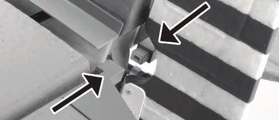
Montage des Höhenruder und des Steuergestänges
Montage des Höhenruders Montieren Sie das linke Höhenruder auf gleichem Weg. Das
Ruderhorn befindet sich unter dem Höhenruder.
1. Schieben Sie den Verbinder durch die Öffnung im Rumpf
Schieben Sie die Ruderverbinder (mit Pfeilen markiert)
zusammen.
2. Schieben Sie das rechte Höhenruderauf den
Flächenverbinder
5. Befestigen Sie das Ruder mit vier (4) Streifen klaren
Klebeband
Hinweis: Bei dem Entfernen des Klebebandes kann Lack mit
entfernt werden.
3. Schieben Sie das Ruder in die Halterung am Rumpf.
8DE
Einsetzen des Flugakkus und Einstellen des Schwerpunktes
Einsetzen des Flugakku
Hinweis: Nachdem Sie die Ruder zentriert haben, ist es sinnvoll
den Empfänger neu zu binden damit die Neutralpositonen
beim Einschalten übernommen werden.
Hinweis: Sollten Sie statt des 1300mAh Akku einen 1800 -
2200mAh Akku verwenden, wird das längere Klettband
benötigt.
ACHTUNG: Vor dem Einsetzen des Akkus sollte der
Empfänger mit angeschlossenem Regler eingebaut sein.
Hinweis: Schalten Sie vor dem Anschluß des Flugakkus immer
zuerst den Sender ein,
1. Schieben Sie den Flugakku (PKZ1033) in den Akkuhalter im
vorderen Teil des Rumpfes. 3. Sichern Sie den Akku mit dem Klettband.
4. Stellen Sie sicher, dass keine Kabel das Schließen der
2. Verbinden Sie den Akku mit dem Regler. Kabinenhaube behindern.
Der Schwerpunkt (CG)
Der Schwerpunkt befindet sich 47mm (+ - 3mm) hinter der
Fügelvorderkante. Dieser Schwerpunkt wurde mit dem 11,1 Volt
1300mAh LiPo Akku ermittelt.
9DE
Testen und Reversieren der Ruderkontrollen
Hinweis: Der Test der Ruderfunktionen beschreibt nicht Mode 5. Bewegen Sie den Seitenruderstick nach links und rechts.
1 oder Mode 2. Wird der Stick nach links gedrückt, bewegt sich das Seitenruder
Bitte sehen Sie in der Bedienungsanleitung ihres Senders zur ebenfalls nach links (von hinten auf das Flugzeug geguckt)
Belegung der Modes nach.
Vor diesem Test sollte der Sender mit dem Empfänger gebunden
sein. Bewegen Sie die Steuerknüppel um die Ruderfunktionen
zu überprüfen.
Note: When using a DSM 2 transmitter, rudder, aileron and elevator
will have to be reversed on the transmitter prior to flight
1. Bewegen Sie den Höhenruderstick am Sender nach vorne
und hinten. Wird der Stick nach vorne gedrückt, sollte sich das
Ruder nach unten bewegen.
6. Wird der Stick nach rechts gedrückt, bewegt sich das
Seitenruder ebenfalls nach rechts (von hinten auf das Flugzeug
geguckt)
2. Wir der Höhenruderstick nach hinten gedrückt, bewegt sich
das Ruder nach oben.
3. Bewegen Sie den Querruderstick nach links und rechts. Wird Sollte bei diesem Test ein Ruder nicht in die beschriebene
der Stick nach links gedrückt, bewegt sich das linke Ruder nach Richtungen laufen, ist es notwendig die Steuerfunktion am
oben und das rechte Ruder nach unten. Sender umzudrehen (zu reversieren) Bitte folgen Sie hierzu den
Anweisungen aus der Bedienungsanleitung Ihres Senders.
4. Wird der Querruderstick nach rechts gedrückt, bewegt sich
das rechte Querruder nach oben und das linke Querruder nach
unten.
10You can also read