Fault-Tolerance by Graceful Degradation for Car Platoons - DROPS
←
→
Page content transcription
If your browser does not render page correctly, please read the page content below
Fault-Tolerance by Graceful Degradation for Car
Platoons
M. Baha E. Zarrouki
TU Berlin, Ernst-Reuter-Platz 7, 10587 Berlin, Germany
baha_zarrouki@mail.tu-berlin.de

Verena Klös
TU Berlin, Ernst-Reuter-Platz 7, 10587 Berlin, Germany
verena.kloes@tu-berlin.de

Markus Grabowski
Assystem Germany GmbH, Gutenbergstraße 15, 10587 Berlin, Germany
mgrabowski@assystemtechnologies.com

Sabine Glesner
TU Berlin, Ernst-Reuter-Platz 7, 10587 Berlin, Germany
sabine.glesner@tu-berlin.de

      Abstract
The key advantage of autonomous car platoons are their short inter-vehicle distances that increase
traffic flow and reduce fuel consumption. However, this is challenging for operational and functional
safety. If a failure occurs, the affected vehicles cannot suddenly stop driving but instead should
continue their operation with reduced performance until a safe state can be reached or, in the case
of temporal failures, full functionality can be guaranteed again. To achieve this degradation, platoon
members have to be able to compensate sensor and communication failures and have to adjust their
inter-vehicle distances to ensure safety. In this work, we describe a systematic design of degradation
cascades for sensor and communication failures in autonomous car platoons using the example of an
autonomous model car. We describe our systematic design method, the resulting degradation modes,
and formulate contracts for each degradation level. We model and test our resulting degradation
controller in Simulink/Stateflow.

2012 ACM Subject Classification Computer systems organization → Embedded and cyber-physical
systems; Computer systems organization → Availability; Software and its engineering → Software
design engineering

Keywords and phrases fault-tolerance, degradation, car platoons, autonomous driving, contracts

Digital Object Identifier 10.4230/OASIcs.ASD.2019.1

 1      Introduction

In autonomous car platoons vehicles drive with short inter-vehicle distances to increase traffic
flow and reduce fuel consumption by travelling in the slipstream. The short distances can
be achieved by exploiting real-time knowledge about the driving behaviour of preceding
vehicles in the platoon. This knowledge is achieved by combining onboard sensors and
wireless communication with platoon members. If a sensor or communication failure occurs,
the required knowledge becomes unavailable and driving within a short distance is not safe
anymore. In contrast to fail-safe systems, where a shut-down of actuators leads to a safe
system state, autonomous vehicles have to be fail-operational, i.e. a shut-down of the vehicle
during operation on a highway is not acceptable. Thus, failures have to be compensated
and adherence to safety restrictions has to be guaranteed even under failure occurrence.
For autonomous car platoons, this means that the inter-vehicle distance always has to be
large enough to allow for an autonomous reaction to a sudden braking of preceding vehicles
            © M. Baha E. Zarrouki, Verena Kös, Markus Grabowski, and Sabine Glesner;
            licensed under Creative Commons License CC-BY
Workshop on Autonomous Systems Design (ASD 2019).
Editors: Selma Saidi, Rolf Ernst, and Dirk Ziegenbein; Article No. 1; pp. 1:1–1:15
                    OpenAccess Series in Informatics
                    Schloss Dagstuhl – Leibniz-Zentrum für Informatik, Dagstuhl Publishing, Germany
1:2 Fault-Tolerance by Graceful Degradation for Car Platoons
without risking a collision. The required reaction time depends on the quality and speed of
information about the behaviour of preceding vehicles, i.e. available sensors and inter-vehicle
communication, and has to be reflected in the distance. One possibility to specify safe and
fault-tolerant driving behaviour for autonomous platoons is to rely on graceful degradation.
This means to systematically define a partial-order of less and less acceptable operation
modes and to select the best achievable mode in presence of failures. Thus, the system
maintains its operation as far as possible. As an example, an autonomous vehicle can be
in the platoon-mode or in a mode of cooperative adaptive cruise control (CACC), where it
only communicates with the vehicle directly in front of it, or in the mode of adaptive cruise
control (ACC), where it relies on onboard sensors only. An operating mode in which the
system is not operated at full functionality due to failures is called degradation mode and a
sequence of less and less acceptable operation modes is called degradation cascade.
With the increasing complexity of vehicles, e.g. due to increasing functionality required for
autonomous driving, the design of degradation cascades becomes challenging, i.e. managing
the resulting amount of failure combinations. In [4], a systematic approach for design
and verification of degradation cascades for embedded systems was presented. Following a
systematic process can help to cope with the increasing complexity. Inspired by this work, we
describe a systematic design of degradation cascades for sensor and communication failures
in autonomous car platoons using the example of the autonomous model car “Velox” which
serves as a case study in the AMASS research project1 . Note that although this paper focuses
on safety, the proposed solutions can also be used to cope with security, i.e. attacks on
sensors, actuators and communication channels, as long as these attacks are identified by some
anomaly detection mechanisms (see [1] for an overview). We describe our systematic design
method, the resulting degradation modes, and formulate contracts 2 for each degradation
level. We model and test our resulting degradation controller in Simulink/Stateflow.
Car Platoons
sensors sensors sensors sensors sensors
3rd Follower 2nd Follower 1st Follower Platoon-Leader
Figure 1 A platoon-drive.
In this paper, we focus on autonomous car platoons with at least two vehicles that drive
with a small inter-vehicle distance on one lane of the highway. They synchronize their speed
and sensor data based on onboard sensors and Vehicle-to-Vehicle (V2V) communication, as
depicted in Figure 1. The platoon members can have different vehicle types (cars, trucks)
from different manufacturers. The vehicle at the front of a platoon is the platoon leader.
1
https://www.amass-ecsel.eu/
2
Contracts are pairs of assumptions and guarantees that define the behaviour of individual system
components to lower the overall complexity of large systems.M. B. E. Zarrouki, V. Klös, M. Grabowski, and S. Glesner 1:3
Based on user-inputs, it determines an efficient velocity and a desired inter-vehicle distance
for the whole platoon. As the safety of inter-vehicle distances depends on individual vehicle
characteristics (i.e. maximum braking deceleration), we assume that each platoon member
adjusts its distance control setpoint such that it is always larger or equal to the individual safe
inter-vehicle distance, and never smaller then the desired distance proposed by the platoon
leader. Furthermore, the leader keeps a safe distance to vehicles or platoons in front of it.
Each following vehicle is a follower (or platoon member) and autonomously has to maintain
the inter-vehicle distance determined by the platoon leader. This is achieved by longitudinal
control, which regulates the speed of the vehicle. The vehicles drive fully autonomously with
a driver who is not prepared to take control, i.e. as if no driver were present.
Outline
This paper is structured as follows: In Section 2, we discuss related work on degradation
concepts for car platoons. In Section 3, we systematically analyze the system architecture,
identify relevant failures for platooning and discuss how to adapt the inter-vehicle distance
to capture slower response times due to less precise information. The results are used to
infer degradation modes for sensor and communication failures. Based on these reactions, we
propose a compact degradation controller that we model in Simulink/Stateflow in Section 4.
To ensure the safety of autonomous platoons that use graceful degradation, we define contracts
and discuss how they can be analyzed and tested with our Stateflow model in Section 5. We
conclude the paper in Section 6 and outline future work.
2 Related Work
In this section, we review related work on fault-tolerant designs and degradation strategies
for CACC and platooning.
The work in [7] proposes a diagnostic system that monitors the sensors of the longitudinal
and lateral controllers in autonomous vehicles that operate in a platoon. However, it does
not detect communication failures and the authors do not define a reaction to the detected
failures. In our work, we assume that sensor and communication failures are successfully
detected and focus on appropriate and safe reactions to detected faults.
The work in [6] presents a graceful degradation technique for CACC in case of commu-
nication failures. The main idea is to estimate the acceleration of the preceding vehicle
based on distance measurement information provided by onboard sensors. This strategy
shows better performance than using ACC as a fallback option. This paper only considers
one possible failure of CACC-mode which is the communication with the preceding vehicle
and does not handle other failures i.e. distance measurement sensor failures that affect the
estimation. In our work, we cover all possible sensor and communication failures affecting
the longitudinal guidance in platoon-mode. Moreover, we define reactions and design a
global state-machine-model that guides the vehicle completely-autonomously in a running
platoon-drive. In our approach, we rely on a similar distance measurement as described in [6]
in case of communication failures with the preceding vehicle.
Our work is similar to and based on the work presented in [9], which introduces a
structured design of degradation cascades for car platoons and a contract-based design
approach to ensure safety. The presented degradation cascade only switches between Platoon,
CACC, ACC and manual driving. In our work, there is no possibility for a fallback to manual
ASD 20191:4 Fault-Tolerance by Graceful Degradation for Car Platoons
driving as we handle fully automated vehicles (SAE Level 5 3 ). Moreover, we introduce new
degradation modes that allow the vehicle to handle more failure combinations and to deliver
a better performance in the platoon.
Our work is inspired by the systematic approach to define, design, implement and
verify degradation cascades for embedded systems presented in [4]. The approach proceeds
systematically from the analysis of the system and its safety over defining degradation
cascades and its requirements down to modelling and generating code from Simulink for
real-time testing. The systematic approach is illustrated with a DC drive example. In our
work, we apply a similar approach on autonomous vehicles in a platoon-drive.
3 Systematic Analysis of Possible Failures and Alternative
Information Sources
In the regular industrial design process, the system design is followed by a safety analysis
to check whether the system adheres to safety requirements. For safe-operational systems
that rely on graceful degradation, possible failures already have to be considered during the
design of degradation modes. Thus, we follow [4], and already perform a systematic safety
analysis before the system design. With this minor change of the usual design flow, the
systematic design of degradation cascades can be easily integrated into industrial practice.
Our systematic design approach for degradation cascades consists of a systematic analysis
of the system architecture to identify a) failure sources that are relevant for platooning,
and b) fallback alternatives for faulty system components. To capture the performance loss
of fallback alternatives, we define individual failure-specific constants that we add to the
reaction time of degraded vehicles. The reaction time describes how long it takes to detect
and react to a sudden change in the behaviour of the preceding vehicle. It is used to define
the safe inter-vehicle distance xrd,i between the i-th vehicle and the preceding vehicle:
xrd,i (t) = xr + tr,i ∗ vi (1)
The parameters of the equation are the remaining distance at standstill xr , the reaction
time tr,i , and the current velocity vi of vehicle i. This distance law assumes similar vehicle
velocities and accelerations in a platoon drive.
Our failure-specific constants describe the additional time that is needed to detect sudden
breaks in the presence of specific failures. They are added to the reaction time tr,i in
equation 1. Based on our analysis results, we define degradation cascades that describe
several degradation steps as a response to sequences of failures. We combine these cascades
into a single and compact degradation controller, which we model in Simulink/Stateflow to
enable simulation, testing and later controller synthesis.
In this section, we first describe relevant parts of the system architecture of the “Velox”
car in Section 3.1. To identify degradation modes for sensor and communication failures, we
identify possible sources for required information about the environment, e.g. the distance
to the vehicle in front, and about other platoon members, e.g. the velocity of the vehicle in
front, based on available sensors and communication partners, and evaluate the influence of
alternative information sources on the reaction time of the autonomous vehicle in Section 3.2.
3
The SAE Norm [8] defines six levels of autonomy for motor vehicle automation ranging from no
automation (level 0) to full automation (level 5)M. B. E. Zarrouki, V. Klös, M. Grabowski, and S. Glesner 1:5
3.1 System Architecture
Within the scope of research projects, experimental cars on a scale of 1:8, the “Velox
Cars”, were developed by “Assystem Germany GmbH”. The prototypes were designed for
training and research purposes as well as for the development of advanced functions of highly
automated systems (HAS) with a focus on autonomous driving. Various driving assistance
functions such as a lane departure warning system, the ACC/CACC/Platoon or the Traffic
Sign Assistant, have been developed. For this purpose, the model cars are equipped with a
valuable range of sensors. In this work, the analysis is based abstractly on the architecture
of the Velox car, which is generally similar to other vehicles.
In this paper, we assume a vehicle architecture as depicted in Figure 2. Each vehicle
is equipped with ultrasonic sensors and a LIDAR (LIght Detection And Ranging) radar
to measure the distance to the vehicle in front. A sensor fusion of the ultrasonic sensor
data and the LIDAR data is performed in order to detect measurement errors. In addition,
the vehicles are equipped with an odometry unit to determine their own driving behaviour
(acceleration, velocity, distance covered and position). A camera and an inertial measurement
unit (IMU) are implemented on the vehicle. However, we assume that they are not used
by the longitudinal controller for the normal Platoon/CACC function. Note that we here
assume a similar architecture and equipment of all platoon members. However, the approach
could also include vehicles that are not fully equipped with sensors or communication devices
by handling these vehicles as vehicles with corresponding senor or communication failures.
Ego-Motion ... Longitudinal
Environment Environment
Data Control Data Velocity
Perception Modelling Platoon/CACC ...
WEnc Data Controller Controller
Wheel-Encoder
Processing Unit Object
LID Data Tracking Data Partner Vehicle
LIDAR
Processing Unit . Data
US Data Partner Vehicle
Ultrasonic Sensor .
Processing Unit Data
. Processing
IMU
Processing Unit V2V Data
Camera
External
Processing Unit
Communication
Figure 2 A simplified vehicle architecture for platooning.
The signal flow in Figure 2 goes from the input on the left to the output on the right.
The input corresponds to the sensors, and the output corresponds to the actuator control.
All sensor data is processed in the corresponding Processing Unit in the Environment
Perception layer. This layer contains function blocks such as the Wheel-Encoder Pro-
cessing Unit, which acquires the odometer data (steering angle and wheel encoder data)
and preprocesses the odometer data. The IMU is only used if the wheel encoder fails. In
the subsequent Environment Modelling layer, the environment is modelled with the help
of different algorithms. This layer contains function blocks such as a Vehicle Detection
block. The Platoon/CACC Controller decides between platoon and CACC mode and
calculates a target velocity to maintain the desired distance between the ego-vehicle and
the vehicle in front. These decisions are based on the partner’s and the ego-vehicle data.
The partner vehicle data are received by the External Communication interface for the
communication between the own vehicle and external systems (Vehicle-to-Vehicle (V2V)
ASD 20191:6 Fault-Tolerance by Graceful Degradation for Car Platoons
communication, GPS etc.). The received V2V data is then filtered by Partner Vehicle
Data Processing. Furthermore, the Platoon/CACC Controller broadcasts the Ego vehicle
data. The Velocity Controller regulates the speed of the vehicle and controls the motor
based on the provided target velocity. We design our degradation concept for the Velox
Car. In practice, it can be assumed that vehicles of different manufacturers participate in a
platoon. Thus, the platoon can be regarded as a heterogeneous system of systems of different
manufacturers. In order to realize the functionality of platoon driving, all vehicles have to
be equipped with relative distance and speed sensors as well as V2V communication. Our
results can easily be transferred to similar architectures.
3.2 Failures, Consequences, and Fallback Strategies
For the platoon operation, a Velox car needs the following capabilities: it can determine the
distance to the vehicle in front, it can measure its own (ego) motion data (acceleration, speed,
distance covered and position), and it can receive the motion of the vehicle in front and of
the first vehicle in the platoon, i.e. the platoon leader. In normal platoon operation, the
distance to the vehicle in front is determined by LIDAR and ultrasonic (US) sensor fusion,
the calculation of the ego-motion is based on the wheel encoder, information about the
front-vehicle motion is available via vehicle-2-front-vehicle communication, and the motion
of the platoon leader is available via vehicle-2-leader communication.
Table 1 Default and Fallback Information Sources.
Kind of Information Default Source 1st Fallback Source 2nd Fallback Source
Distance to vehicle in LIDAR and Ultra- LIDAR only, Ultra- GPS and Wheel-
front sonic sensor fusion sonic only Encoder (for commu-
nication packet iden-
tification only)
Ego-Motion Wheel-Encoder Inertial- Motor-model for
Measurement- speed estimation
Unit (IMU)
vehicle in front mo- vehicle-2-Front vehicle-2-Leader based on distance
tion vehicle (V2F) (V2L) measurement
Motion of Platoon V2L V2F -
Leader
In the case of sensor and communication failures, the required information has to be
obtained from alternative sources. In Table 1, we summarize available information sources in
the Velox car and introduce new sources for the fallback scenario. If, for example, the LIDAR
fails, ultrasonic data can be used without sensor fusion. However, the obtained information
is less precise. If this sensor also fails, the system can still rely on the second fallback option:
a combination of GPS and wheel-encoder that is precise enough to identify communication
packets from the vehicle in front, but not for ACC-mode.
In the following, we describe the identified fallback possibilities for sensor and commu-
nication failures and their influence on the reaction time to changes in the behaviour of
preceding vehicles. The resulting delays are expressed in terms of failure-specific constants.
These constants have to over-approximate the actual delays as precisely as possible to ensure
that the distance to the vehicle in front is as small as safely possible. The actual values
depend on the characteristics of the sensors, actuators and the efficiency of the algorithms
(fusion of data, recognition etc.) and can be determined with simulations and real-time tests.M. B. E. Zarrouki, V. Klös, M. Grabowski, and S. Glesner 1:7
Failure in Distance Measurement
In case of a failure of the LIDAR (LID_F) or the US sensor (US_F), it is no longer possible
to use sensor fusion to increase precision, but we can still rely on the remaining sensor. As a
result, the reaction time increases due to less precise sensor data. We capture this by adding
a constant failure-specific factor, e.g. tr_lid1 for LIDAR failures and tr_us1 for US failures,
that captures the necessary increase of the reaction time, to the reaction time in the normal
platoon operation tr_pl. Thus, we get tr_pl+tr_lid1 and tr_pl+tr_us1, respectively. It
applies tr_lid1 > tr_us1, since the LIDAR is more accurate than the ultrasonic sensor.
If both distance sensors fail, the system can still rely on a combination of GPS and
wheel-encoder to identify communication packets from the vehicle in front. In this case,
tr_lid_us is added to the reaction time. However, this is not precise enough for CACC-mode.
Failure in estimating the Ego-motion
An error in the wheel encoder (WEnc_F) affects the acquisition of the covered distance, the
own acceleration and speed (Ego-Motion-Data). If a wheel encoder error occurs, the system
can still obtain 3-axis acceleration data from the motion sensor (inertial measuring unit
(IMU)). However, this information is less precise. Accordingly, the reaction time increases to
tr_pl+tr_wenc. If the IMU fails (IMU_F), it is still possible to roughly estimate the own
velocity based on electrical values by using a motor model as discussed in [4]. The reaction
time has to be increased to tr_pl+tr_wenc_imu.
Communication Failures
In the platoon operation, each vehicle communicates with the platoon leader and the vehicle
in front of it. If the communication with the vehicle in front fails (V2F_F), the vehicle in
front motion can only be estimated using the slower distance measurement, which means
that the reaction times, and, thus, the safety distance, have to be increased when switching
to the corresponding ACC mode. However, if communication to the platoon leader is still
available, the platoon leader could be requested to forward messages from the vehicle in front.
To this end, an extended packet filtering algorithm has to be implemented in the Partner
Vehicle Data Processing.
If an error in the communication with the platoon leader (V2L_F) occurs (e.g. error
during a sending procedure or error with the reception), we lose any information about the
leader’s driving behaviour. As a consequence, we would need to switch to the CACC mode
and increase the inter-vehicle distance accordingly. However, if the vehicle in front is still
able to communicate with the platoon leader and the ego vehicle has a stable communication
connection to the vehicle in front, this vehicle can forward messages from the platoon leader.
As message forwarding introduces some communication delay, reactions to sudden changes
in the behaviour of the vehicle in front / the leader will also be delayed. Thus, the reaction
time increases to tr_pl + tr_front and tr_pl + tr_lead, respectively.
Based on the results of a systematic evaluation of available fallback possibilities for
relevant sensor and communication failures, we define corresponding degradation modes for
each combination of evaluated failures in the next section.
ASD 20191:8 Fault-Tolerance by Graceful Degradation for Car Platoons
4 Degradation Controller
With our systematic analysis, we have identified fallback alternatives to compensate for
sensor and communication failures within a running platoon-drive. In this section, we use the
analysis results to infer degradation modes that describe less and less acceptable operation
modes for platoon members. We propose a controller, modelled in Simulink/Stateflow, that
safely guides the graceful degradation. Note that we assume the existence of a reliable and
sufficiently fast fault detection method that we can rely on. This, of course, is not trivial, but
out of the scope of this work. Our controller receives fault detection events from the fault
detector and selects the best mode based on these events. The Stateflow model is used for
systematic testing in the next section and can be further refined for controller code synthesis.
4.1 Degradation Cascades
In case of failure combinations of different information types, our fallback strategies from
the previous section can be combined step-by-step as long as information alternatives are
available. If only knowledge about the platoon leader is missing, the vehicle can still switch
to CACC and rely on vehicle-2-front-vehicle communication. If this communication also fails,
only onboard sensor-based ACC may be possible. However, degradation is only possible as
long as any acceptable operation mode can be executed. Thus, the last degradation step
leads to a final degradation mode FIN_DEG, which describes a safe exit from the platoon.
At this point, the system cannot rely on important sensor information and may not be able
to communicate with other vehicles. Thus, it should come to a standstill as far to the right
as possible, brake and warn other road users.
4.2 Controller Model
The Stateflow model, as depicted in Figure 3, consists of three hierarchical modes. The system
starts in the nominal platoon mode. Failures cause a transition to the degraded platoon
mode. If failures are resolved, it returns to nominal platoon mode. If no further acceptable
degradation is possible, the last step leads to the final degradation mode (FIN_DEG).
Figure 3 Main Statechart.M. B. E. Zarrouki, V. Klös, M. Grabowski, and S. Glesner 1:9
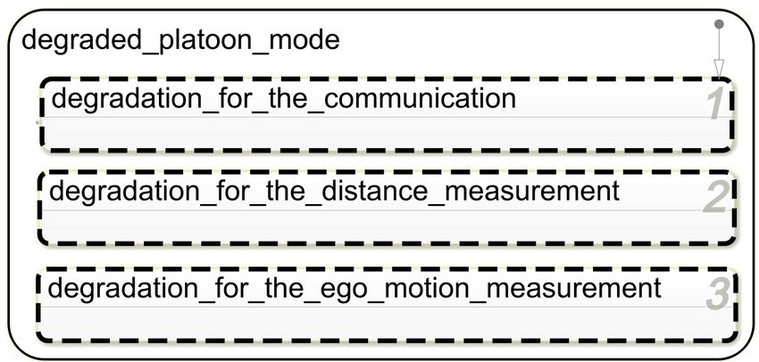
Figure 4 Statechart for the Degraded Platoon-Mode.
The degraded platoon mode, as depicted in Figure 4, consists of three parallel states,
which in turn contain further state machines: Degradation for the communication (Figure 5),
Degradation for the distance measurement (Figure 7) and Degradation for the ego motion
measurement (Figure 8) according to the failure categories: communication failures, failures
in distance measurement and failures in measurement of the ego-motion. In each parallel
state, the reaction time is adjusted as described in the previous section. The overall reaction
time is the sum of the normal reaction time tr_pl and all added constants. If, for example,
an error occurs in the LIDAR, in the communication with the vehicle in front and in the
wheel encoder, the reaction time to be added is the sum of tr_lid, tr_front and tr_wenc.
Figure 5 Degradation for Communication Failures.
The state machine for degradation in case of communication failures is shown in Figure 5.
The initial state “wait” corresponds to states without any communication errors. This state
is active if the degraded platoon-mode is activated without communication errors, but with
an error in the distance measurement or in the measurement of own motion. There are three
different variants of degradation for communication: the failure is due to communication with
the platoon leader (V2L_F), with the vehicle in front (V2F_F), or with both. When a failure
ASD 20191:10 Fault-Tolerance by Graceful Degradation for Car Platoons
in the communication with the platoon leader (V2L_F) occurs, we switch to a degradation
mode for communication with the leader. If the failure is resolved, the system returns to
“wait” again. Failures within the communication with the vehicle in front (V2F_F) are
handled analogously. If the communication with both, the leader and the preceding vehicle,
is corrupted, the ACC mode is activated (ACC_m=true) and the ACC-specific constant
tr_acc_offset is added to the reaction time. When this state is left, the offset is subtracted
again. The same holds for a switch to the CACC mode, where tr_cacc_offset is added.
It contains a sub-state machine for corrupted communication with the platoon leader
(DEG_L)as shown in Figure 6(DEG_F is similar and, thus, omitted here). The vehicle
switches to CACC mode (CACC_m=true) and tr_cacc_offset is added to the reaction time.
At the same time, a request for the data of the platoon leader is sent to the preceding vehicle.
When this data is received (pos_resp_F), the vehicle changes to a degraded state (DEG_L1)
and the reaction time is increased by tr_lead. If the preceding vehicle looses connection to
the platoon leader (F2L_F), the system returns to CACC mode. During this process, the
system continuously tries to re-establish the communication with the platoon leader in order
to switch back to an operating mode with a better performance.
Figure 6 Degradation for Communication Failures with the Leader.
The state machine for degradation in case of distance measurement failures is depicted
in Figure 7. The LIDAR and the ultrasonic sensor are mainly used for the identification
of the received communication packets or for precise distance measurement in ACC mode.
Starting from a wait state (wait), the system switches to a degraded state (DEG_LID1)
and relies on the ultrasonic sensor for identification of communication packets if a LIDAR
error occurs (LID_F). tr_lid1 is added to the reaction time. However, when ACC mode is
active (ACC_m), it switches to a degraded state (DEG_LID2) and relies on the ultrasonic
sensor for precise distance measurement. tr_lid2 is added to the reaction time. The same
applies if an error occurs in the ultrasonic sensor, i.e. tr_us1 or tr_us2 are added to the
reaction time and only the LIDAR is used. The following applies: tr_lid2 > tr_lid1 and
tr_us2 > tr_us1. For failure-free communication, an estimate is sufficient to identify the
communication packets. If the communication is faulty, an exact distance measurement is
needed. Thus, the reaction times tr_lid2 and tr_us2 are higher.M. B. E. Zarrouki, V. Klös, M. Grabowski, and S. Glesner 1:11
If the data of both sensors are faulty, the system switches to a degradation state in which
it relies on the GPS and the wheel encoder to identify communication packets. Compared to
the positions of platoon partners that were received via V2V communication, communication-
packets of the vehicle in front and the platoon leader can then be filtered. tr_lid_us is
added to the reaction time in this case. This degradation is only possible if communication
is available. Otherwise, the vehicle passes to the final degradation state (FIN_DEG).
Figure 7 Degradation for Distance Measurement Failures.
Figure 8 Degradation for the Measurement of Own Motion.
ASD 20191:12 Fault-Tolerance by Graceful Degradation for Car Platoons
In Figure 8, we depict the state machine for degradation in case of measurement failures
of the ego-motion. Starting from a wait state (wait), the system switches to a degraded state
(DEG_WENC) and relies on the inertial measurement unit to determine its own acceleration
if an error occurs in the wheel encoder (WEnc_F). tr_wenc is added to the reaction time.
If the inertial measurement unit is faulty too, we switch to a degraded state
(DEG_WENC_IMU) and add tr_wenc_imu to the reaction time. In this mode, a motor
model is introduced which estimates the motor speed from electrical values without using the
physical speed sensor. The introduction of the motor model was discussed in [4]. Although
the speed is not estimated very well, an estimation is better than a complete loss of the
measurement of the ego-vehicle motion.
The proposed fallback concept can be further refined by changing reactions to failures or
adding new actions. For example, in case of a distance measurement failure, the cameras
can be used to estimate the distances. Furthermore, the logical expression that leads to
the final degradation state can also be adjusted. This can be useful, for example, if it is
determined during simulation or testing that a safe distance cannot be maintained for a
certain combination of failures. The presented controller model contains degradation steps
for all failure combinations that were considered during our systematic system analysis.
To ensure that the controller is complete and that the reaction time estimate is safe, i.e.
leading to a safe distance to the preceding vehicle, we systematically tested our controller, as
described in the next section.
5 Assurance by Mode-Specific Contracts
To ensure a safe operation of vehicles, standards like ISO26262 [3] define concepts and
procedures which need to be considered during the development of safety-critical functions.
These standards explicitly recommend a formal system description for heavily safety-critical
systems like our car platoon. Based on the formal system description, methods like model
checking allow a partly or fully automated way of verifying and validating the system early
during development. A promising approach to this is Contract-based Design[5]. By specifying
pairs of assumptions and guarantees the behaviour of each system component can be defined
on its own and thus lowering the overall complexity of large systems. The composition of
components and their contracts can then be evaluated.
To validate our degradation controller we specify contracts in SSPL (System Specification
Pattern Language)[2], which enables a formal and verifiable description of behaviour while
also maintaining a readable appearance. We came up with 11 contracts which describe the
degradation of the platooning function. As an example, the contract defining the minimum
distance to the vehicle in front while platooning is active and no errors occur (nominal
platoon-mode) looks as follows:
Assumption all of the following conditions hold:
- platooning is ACTIVE
- com_error does not occur
- distance_meas_error does not occur.
Guarantee 1 distance_to_front is always greater than d_min_pl
Guarantee 2 Whenever break_maneuver_front occurs then in response dis-
tance_to_front is never less than distance_at_standstill starting immediately.M. B. E. Zarrouki, V. Klös, M. Grabowski, and S. Glesner 1:13
As a second example, we show a contract specifying a switch to ACC-mode (drv_mode
= ACC) when the communication to the platoon head and the preceding vehicle is lost:
Assumption No specific assumption. The contract’s guarantees shall always hold.
Guarantee 1 Whenever V2L_F changes to true while all of the following conditions hold:
- V2F_F is true
- drv_mode is not FIN_DEG
then in response drv_mode changes to ACC eventually.
Guarantee 2 Whenever V2F_F changes to true while all of the following conditions hold:
- V2L_F is true
- drv_mode is not FIN_DEG
then in response drv_mode changes to ACC eventually.
As a first step towards a verified degradation controller, we have implemented and automated
tests based on these contracts in Simulink to successfully check the state machines against
our specification. To this end, we have simulated our controller in the presence of specific
failure combinations and checked whether our guarantees hold. Figure 9 gives an overview
of internal failures and external events that we have used for systematic testing of failure
combinations. Expressing our system behaviour with semi-formal contracts in SSPL, has
eased writing proper test cases for our state machines.
Figure 9 Simulink/Stateflow model used to verify against contract specification.
6 Conclusion & Future Work
We have described a systematic design of degradation cascades for sensor and communication
failures in autonomous car platoons using the autonomous model car “Velox” as example.
We have modelled our resulting degradation controller in Simulink/Stateflow. For safety
assurance, we have formulated contracts for each identified degradation level and used them
for systematic testing. The methodology of the present work and its systematic approach is
ASD 20191:14 Fault-Tolerance by Graceful Degradation for Car Platoons
inspired by [4] and has been adapted for the platooning function. In our work, new ideas for
degradation and reactions to errors have been developed and presented at a conceptual level.
It can serve as a basis for further improvement, development and implementation in future
work. The systematic approach presented in this paper is not restricted to autonomous
platoon driving but can also be applied to other problems and different systems in general.
In contrast to traditional, non-distributive systems, cooperative systems should not
only deal with local failures, but also with failures of the other participants. Failures can,
if possible, be transmitted via communication. However, if this is not possible due to
communication failures, participants should also be able to deal with this situations and
reach a functional and safe state. In future work, the degradation concept could be extended
to feature additional modes allowing platoon members to autonomously determine which
members are affected by malfunctions. For example, if a platoon member can only estimate
its own acceleration with poor accuracy due to sensor failures, it will communicate its
degradation mode to the other platoon participants. Another approach would be to define
reactions beyond the consideration of individual vehicles on a platoon level. For example,
if the platoon leader cannot be reached by several followers, the platoon leader could be
changed, e.g. by choosing the next achievable follower as a new platoon leader. This kind of
platoon management has not been systematically coped with so far and would definitely be
a mandatory step for a robust and applicable platooning functionality.
As a first step, we have tested our concept based on formal contract specifications. By
expressing our system behaviour with semi-formal contracts in SSPL, it has already been
much easier to write proper test cases for our state machines. In future work, we aim at
automatically verifying our contract specification against the static system architecture using
model checking. A promising candidate is the model checking tool OCRA4 as it already
supports this type of contract verification. We are currently developing a translation from
SSPL to Othello, the contract specification language supported by OCRA. With an automatic
translation, the engineers will not have to cope with difficult expressions in temporal logic
but can rather use our template approach to specify and verify their systems.
References
1 Jairo Giraldo, David Urbina, Alvaro Cardenas, Junia Valente, Mustafa Faisal, Justin Ruths,
Nils Ole Tippenhauer, Henrik Sandberg, and Richard Candell. A Survey of Physics-Based
Attack Detection in Cyber-Physical Systems. ACM Computing Surveys (CSUR), 51(4):76,
2018.
2 Markus Grabowski, Bernhard Kaiser, and Yu Bai. Systematic Refinement of CPS Requirements
using SysML, Template Language and Contracts. In Ina Schaefer, Dimitris Karagiannis,
Andreas Vogelsang, Daniel Méndez, and Christoph Seidl, editors, Modellierung 2018, pages
245–260, Bonn, 2018. Gesellschaft für Informatik e.V.
3 ISO. ISO 26262 Road vehicles - Functional safety. Standard, International Organization for
Standardization, 2011. In several parts: 1: Vocabulary, 2: Management of functional safety,
3: Concept phase, 4: Product development at the system level, 5: Product development
at the hardware level, 6: Product development at the software level, 7: Production and
operation, 8: Supporting processes, 9: Automotive Safety Integrity Level (ASIL)-oriented and
safety-oriented analyses, 10: Guideline on ISO 26262.
4
Othello Contracts Refinement Analysis, https://ocra.fbk.eu/M. B. E. Zarrouki, V. Klös, M. Grabowski, and S. Glesner 1:15
4 B Kaiser, B Monajemi Nejad, D Kusche, and H Schulte. Systematic design and validation of
degradation cascades for safety-relevant systems. In Annual European Safety and Reliability
Conference ESREL, 2017.
5 Bernhard Kaiser, Raphael Weber, Markus Oertel, Eckard Böde, Behrang Monajemi Nejad,
and Justyna Zander. Contract-based design of embedded systems integrating nominal behavior
and safety. Complex Systems Informatics and Modeling Quarterly, 4:66–91, 2015.
6 Jeroen Ploeg, Elham Semsar-Kazerooni, Guido Lijster, Nathan van de Wouw, and Henk
Nijmeijer. Graceful degradation of CACC performance subject to unreliable wireless com-
munication. In 16th International IEEE Conference on Intelligent Transportation Systems
(ITSC), pages 1210–1216. IEEE, 2013.
7 Rajesh Rajamani, Adam S Howell, Chieh Chen, J Karl Hedrick, and Masayoshi Tomizuka.
A complete fault diagnostic system for automated vehicles operating in a platoon. IEEE
Transactions on Control Systems Technology, 9(4):553–564, 2001.
8 SAE International. Taxonomy and Definitions for Terms Related to On-Road Motor Vehicle
Automated Driving Systems, January 2014. doi:10.4271/J3016_201401.
9 Irfan Sljivo, Barbara Gallina, and Bernhard Kaiser. Assuring degradation cascades of car
platoons via contracts. In International Conference on Computer Safety, Reliability, and
Security, pages 317–329. Springer, 2017.
ASD 2019You can also read