Features, Benefits, and Operation - 2013 Decibel Eleven
←
→
Page content transcription
If your browser does not render page correctly, please read the page content below
Features, Benefits, and Operation
         © 2013 Decibel Eleven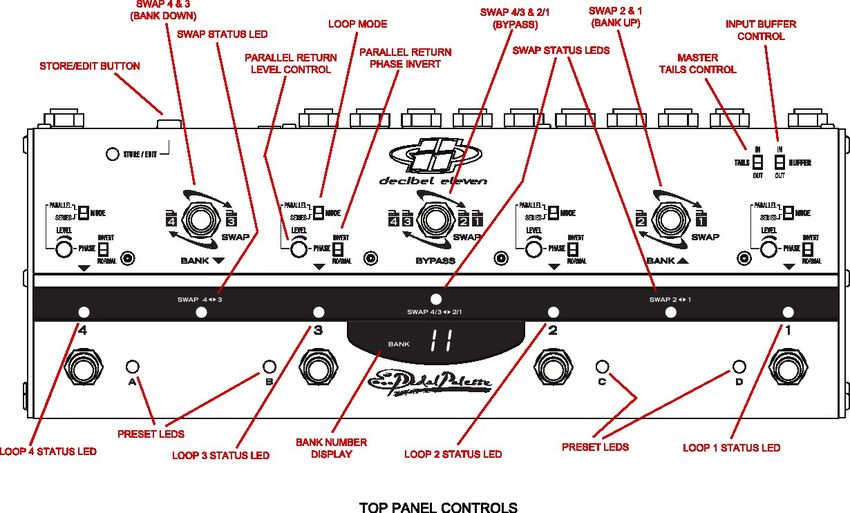
Features, Benefits, and Operation
Contents
Introduction......................................................................................... 2
Features.............................................................................................. 2
Top Panel Controls.............................................................................. 3
Operation Basics................................................................................. 4
Connections......................................................................................... 5
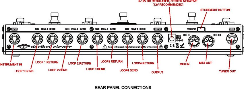
Rear Panel Diagram............................................................................ 7
True Bypass......................................................................................... 8
Series Connection............................................................................... 8
Order Swapping................................................................................... 9
Parallel Mix Bus................................................................................... 10
Tails Control......................................................................................... 12
Buffering.............................................................................................. 13
Operating Modes................................................................................. 14
Preset Control...................................................................................... 14
MIDI Control......................................................................................... 15
Settings Mode......................................................................................17
MIDI Sysex Data Dump....................................................................... 18
Specifications...................................................................................... 19
Declaration of Conformity
Decibel Eleven declares that this product complies with the European Union Council Directives and Standards
requirements for the Low Voltage Directive (2006/95/EC) and the EMC Directive (2004/108/EC).
© 2013 Decibel Eleven
1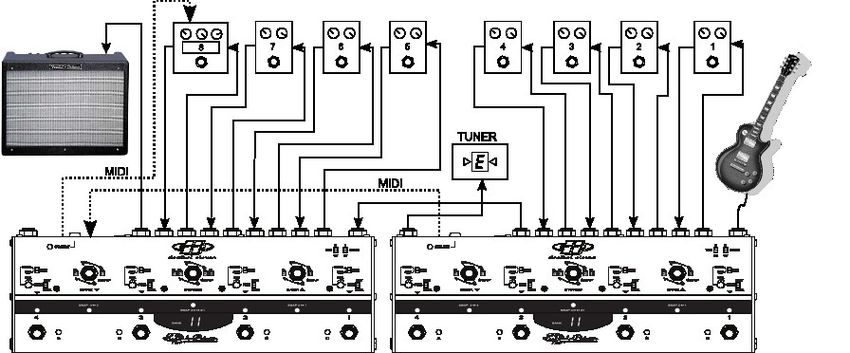
Introduction
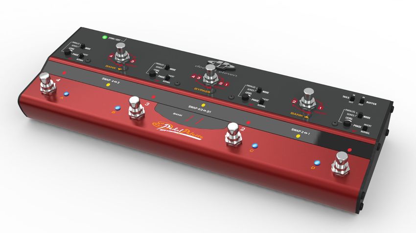
The Pedal Palette, at it's core, is a four loop, true bypass switcher designed to preserve guitar tone
and signal when pedal effects are bypassed. It features the ability to store and recall preset
combinations of pedals, enabling the user to switch multiple pedals in and out of the effect chain
simultaneously with a single button press. In addition to these base features, the Pedal Palette
expands your sonic palette by adding an available parallel mix bus to all effect returns, and adding
the ability to change the order of the effects on the fly.
The Pedal Palette is a creative tool designed with an intuitive user interface, making experimentation
simple and easy. Reading the entire manual is not necessary to begin enjoying the benefits of the
Pedal Palette, but it is highly recommended for a full understanding of it's features and operation.
Features
• 4 Pedal Effects Loops
• True Relay Bypass
• Fully Analog Signal Path
• Swap Pedal Order Instantly
• Blend any effect in Parallel
• Reverb and Delay Tails Control
• Optional Discrete Class A Input Buffer
• 128 Presets
• Send and Receive MIDI Program changes
Website
Go to decibel11.com for videos, manuals, accessories, and more.
Contact us directly at support@decibel11.com.
2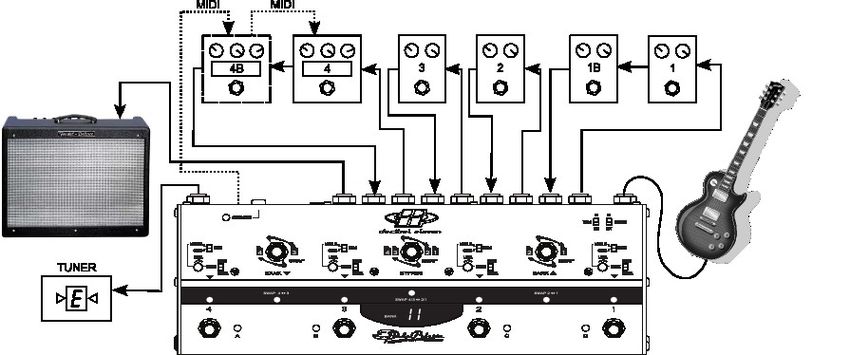
Operation Basics
This section describes the basic controls of the Pedal Palette. It is meant as a general introduction
and a guide for those wanting to get started immediately. This section only covers DIRECT MODE
functionality, which is the factory set default mode. For PRESET MODE operation, see the Preset
Control section [page 14].

Loop Mode Settings
Each loop can be configured to have either a series or parallel connection. Use the MODE switch to
select the desired mode. When the loop is in PARALLEL mode, it's return signal can be blended, or
mixed, into the Pedal Palette signal path using the LEVEL knob and the PHASE switch. For more
information on loop modes, see the Series Connection and Parallel Mix Bus sections [page 8 & 10].
NOTE: Changing the MODE settings can cause a loud click or snap with high gain amplifiers. It is
advised to keep volume low when switching these.

Controlling the Loop States
The bottom row footswitches (1-4) are used to turn the loops on or off. Status is indicated by the RED
LED directly above the switch.

Swapping the Loop Order
The top row footswitches are used to swap the order of the effects. The right-most footswitch will
reverse the order of loops 1 & 2 when activated. It's status is indicated by the YELLOW LED directly
below the footswitch. The left-most footswitch will reverse the order of loops 3 & 4 when activated.
The center footswitch reverses the order of the loop 1&2 section and the loop 3&4 section when
activated. For more information on swapping, see the Order Swapping section [page 9].

Input Buffer
When the BUFFER switch in the upper right corner is set to IN, the input buffer is active in circuit.
Setting the switch to OUT will bypass the input buffer circuit. For more details on how Pedal Palette
buffers work, see the Buffering section [page 13].

Tails Control
The TAILS switch in the upper right corner is the master setting for tails control. When this switch is
set to IN with at least one loop in parallel mode, the parallel mix bus circuit is always active. With the
switch OUT, the parallel mix bus is only active when a parallel mode loop is turned ON. For additional
control, loops can be individually configured for tails in or out [see Tails Control section – page 12].

                                                     4
Storing a Preset
A loop combination can be stored as a preset by pressing and holding the STORE/EDIT button. The
green STORE/EDIT LED will light, a bank number will be displayed, and the BLUE preset LEDs will
flash in sequence. Select the preset location to store to by first using the BANK UP and BANK DOWN
switches to select the desired bank, and then using the bottom row footswitches to select the preset
location (A-D) within the bank. Once the Bank/Preset combination is selected, press the STORE/EDIT
button again to save the preset and return to normal operation. For more details, see the Preset
Control section [page14].
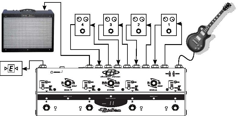
Connections
Refer to the drawings below and to the REAR PANEL CONNECTIONS figure on page 7. Each loop of
the Pedal Palette can accommodate one or more effect pedals. The SEND jack of each loop is
connected to the input of the pedal for that loop. If more than one pedal is used in the loop, then
connect the SEND to the input of the first pedal in the loop. Connect the output of the pedal (or last
pedal if more than one pedal is used in a loop) to the RETURN jack. Connect your instrument to the
INPUT jack, and connect the OUTPUT jack to the amplifier, additional pedal, or other destination.
The Pedal Palette can also be used in the effect loop of an amplifier for parallel mixing of modulation
pedals within the amp's loop. The TUNER jack can be used for “always on” tuning.
Power
The Pedal Palette can be powered by 9VDC or 12VDC at 300mA. It is highly recommended that a well
regulated and isolated 12V, 300mA (minimum) power supply is used for best performance. The
power inlet jack is a standard 2.1mm DC power jack, center negative connection.
Simple setup with one pedal per loop
5Expanded setup with optional multiple pedals per loop and MIDI
Pedal Palette in Amplifier's Effect Loop – Multiple Modulation Effects in Parallel
Expanded setup using two Pedal Palettes
6True Bypass
Passive guitar pickups are low level, high impedance sources. This means they are easily loaded
down by all the various cable and connections required when using multiple effect pedals, resulting in
a loss of high frequency response.
Many effect pedals on the market employ circuitry that is active even when the effect is turned off.
While this design allows for silent switching, the “bypass” circuitry typically has high harmonic
distortion and minimal headroom, both of which can greatly affect the tone and dynamics of your
playing. Other pedal designs use a bypass scheme where the effect's input circuitry remains
connected even when bypassed. This type of pedal continues to load the guitar signal even when the
pedal is switched off.
These types of pedal bypass issues have a cumulative effect. And, with several pedals in your effect
chain, they can result in a loss of tone, dynamics, and high frequency response - even when all your
pedals are OFF.
A true bypass pedal will completely disconnect all circuitry from the guitar signal and will route the
pedal input directly to the pedal output. This provides the most “pure” signal path. However, even if
all the pedals in your effect chain are true bypass, there still exists the possibility of poor signal
caused by all of the cables, connectors, and switches that your guitar signal must travel through.
The Pedal Palette is a true bypass switcher. The advantage to having all of your effect pedals
connected through the Pedal Palette is that, when all of the pedal loops are switched off, your guitar
signal goes directly from the input jack to the output jack, bypassing all of the cables, connectors and
pedals in the effect chain.* In order to achieve a “straight wire” type of true bypass, the Pedal Palette
utilizes relays. This provides the most transparent bypass possible. However, because relays are
mechanical switches, it is understood that they inherently cause some noise when switching.
* when the Input Buffer and Tails switches are off.
Series Connection
Guitar effect pedals are typically wired in what is known as a “series” configuration. What this means
is that the guitar is plugged into the first pedal, the output of the first pedal goes to the input of the
second pedal, the output of the second pedal goes into the third pedal, etc. [see Figure 1]. This
configuration makes it simple and easy to see what the signal path is. However, the series
configuration is limited in several ways. The series order of the effects is fixed and cannot be
8changed. And, the effects cannot be blended or mixed. Digital multi-effect processors have long been
able to obtain more complex and flexible routing and mixing capabilities. And, recording engineers will
often use multiple effects mixed in parallel to create lush and complex soundscapes. With the Pedal
Palette it is now possible to obtain these types of results with analog routing and mixing for your
favorite pedal effects.
Order Swapping
Typically, the order of your pedals in your effect chain is determined by trial and error, and through
general consensus. However, many times an alternate order of pedals can result in an equally useful
and effective sound effect. The Pedal Palette gives you the ability to swap the order of your effects in
real-time. In some cases, this can result in drastic differences. This is particularly true with tone or
frequency modifying effects such as distortion, wah, or EQ pedals. In other cases, the result is more
subtle, where one effect becomes more predominate than the other(s). Modifying effect pedal order
is great when searching for just the right sound, and it greatly expands your available sonic options.
The top row of footswitches, labeled SWAP , allow the order of the effects to be changed. The right-
most SWAP switch reverses the order of loops 1&2. The left-most SWAP switch reverses the order of
loops 3&4. The middle SWAP switch reverses the order of the loop 1&2 section and the loop 3&4
section [see Figure 2]. This method allows many possible order combinations while still being intuitive
and easy to understand. The YELLOW swap status LEDs provide simple visual feedback, making it
ideal when swapping live and in real time.
9Parallel Mix Bus
Parallel mixing has long been a useful method of achieving a desired sound effect. It is a standard
method used with reverbs and delays. All reverb and delay pedals have some type of parallel mixer
built into them. The signal seen at the input to the effect, referred to as the “dry” signal is mixed with
the delayed output of the effect (the “wet” signal). Some pedals convert the direct “dry” signal to
digital and mix it with the “wet” signal digitally before converting back to analog. Other pedals keep
the direct “dry” signal analog and mix analog. In many cases the mix is controlled through a “blend”
knob which balances the amount of “dry” signal with the amount of effected “wet” signal.
The parallel mix bus in the Pedal Palette works in a similar way, by taking the pedal's output at the
loop return jack and mixing it with the “dry” signal obtained within the Pedal Palette. In this case,
however, since the Pedal Palette has more than one effect (loop), the “dry” signal is not always the
signal at the input jack. It could also be the signal output from any active SERIES mode loop(s).
Setting a Loop in Parallel Mode
To configure a loop in parallel, set the loop MODE slide switch to PARALLEL. Once the switch is set to
PARALLEL, the loop's send signal is split and also sent to the following loop's send jack. The return
signal of the loop will now be routed to the parallel mix bus instead of to the next loop's send. See
Figure 3 below showing the signal routing when a loop is in parallel.
Level and Phase Invert Controls
When a loop is set to PARALLEL mode, there are two additional controls which can be used to set the
desired blend of the effect. The LEVEL control is used to set the amount of effect return that is mixed
in. The PHASE switch inverts the phase of the effect return. Some effect pedals will invert the phase
of the signal such that their output is out of phase with their input. With these types of effect pedals,
it will be necessary to use the INVERT position to correct the phase before mixing. Other pedals may
have some phase shift, but may not be completely out of phase. For these reasons, some
10experimentation with the PHASE switch settings is recommended. If the effect gets weaker when the
LEVEL control is turned all the way clockwise, this is an indication that the effect is out of phase, and
the PHASE switch should be toggled. In any case, use what sounds best.
Parallel Reverb and Delay
There are several practical advantages to using the Pedal Palette with delay and reverb pedals:
• The direct guitar signal remains analog. Since your “dry” sound is no longer obtained from the
effect pedal, your guitar signal will not be converted to digital and back again (as some pedals
do). Also, your “dry” guitar signal level remains consistent and it is not modified and re-mixed
at each reverb and delay pedal in the chain, which can add noise.
• Delay and reverb tails, or echoes, can continue to decay naturally after the effect is switched
off. Delay and reverb pedals that are true bypass must abruptly cut-off the reverb and delay
tails when switched off. With the Pedal Palette, their echo tails are allowed to fade out [see
Tails Control section – page 12].
• Multiple delay and/or reverb pedals active in an effects chain can all be fed the same input
signal. Using both a delay and a reverb on a source is a common technique in recording
studios. However, the same result can not be achieved in a typical series pedal effect chain.
This is because, in the series chain, one of the two effects must always come first, putting it's
imprint on the sound before reaching the second effect. With the Pedal Palette, it is now
possible to send the same input signal to both the reverb and delay effects, and then mixing
their “wet” outputs together with the “dry” signal using the parallel mix bus.
When using delay and reverb pedals in PARALLEL mode with the Pedal Palette, it is important to set
the “blend” or “mix” setting on the pedal(s) to 100% “wet”. The blending will now be controlled with
the loop's LEVEL control on the Pedal Palette. In some pedals, there may be an internal setting for
“kill dry” which can also achieve the same result.
Creative Uses of Parallel Mixing
Parallel effects mixing is widely used in recording studios as a creative tool for blending all types
effects to achieve a more distinctive soundscape. Many of these same techniques can be applied
using guitar pedal effects with the Pedal Palette. For example, the intensity of a chorus or flanger can
be easily controlled by using a parallel mix bus to blend the amount of effected signal with the direct
signal. Mixing a compressor in parallel can “fatten” the sound, while still retaining dynamics, by
blending the direct tone with a heavily compressed tone. Likewise, a distortion pedal can be blended
11with a clean tone to create a bigger, more dynamic sound.
When used in combination with effects order swapping, the parallel mix bus can yield some
interesting results. Many times, parallel mixed effects, such as delay, are used at the end of the
chain. This allows additional series effects to be inserted in front of it, with the result being that the
delay receives the affected sound. In the Pedal Palette, if the order is swapped, the result is that the
delay is now fed the clean guitar signal and the series effect is also fed the clean guitar signal,
creating a dual signal path. The outputs from both effects are then mixed via the parallel mix bus.
With some experimentation, many unique results can be achieved [see Figure 4].
Tails Control
When using reverb and delay pedals, it is often desired to have the tails, or echoes, decay naturally
after the effect is shut off. True bypass pedals inherently cut-off the echoes abruptly when the pedal
is turned off. With the TAILS control on the Pedal Palette, the send to the pedal will be muted when
the loop is off. But, the pedal return will remain connected to the mix bus, allowing the residual
echoes to ring out. This is a very useful feature when used with a reverb or delay pedal, however it
can be problematic when using the parallel mix bus with pedals that do not have echoes, and which
may be noisy. For this reason, each effect loop can be individually configured for tails IN or OUT
12Individual Loop Tails Control
Individual TAILS control for each loop is configured in SETTINGS MODE. To enter SETTINGS MODE,
press the SWAP 1-2 footswitch and the SWAP 3-4 footswitch simultaneously. The display will read SE
and the BLUE preset LEDs will sequence. To enter SETTINGS - TAILS, select the A footswitch. The
display will now read “tL and the current TAILS setting for the loops is displayed by the RED
loop status LEDs. The loop on/off footswitches are used to set the TAILS mode for each loop. When
the RED loop status LED is lighted, the TAILS for that loop is IN. When the LED is off, TAILS are OUT.
To exit SETTINGS - TAILS, press the STORE/EDIT button once to return to the SETTINGS main menu,
and press STORE/EDIT a second time to return to the current operating mode.
Master Tails Switch
The top panel TAILS switch acts as a master switch for tails control. When the TAILS switch is set to
IN, and there is at least one loop configured in PARALLEL mode, the mix bus will always be active in
circuit. When the TAILS switch is OUT, the mix bus is active in circuit only when a PARALLEL mode
loop is active, and the parallel mix bus is bypassed when no PARALLEL mode loops are active.
Buffering
The Pedal Palette can be configured to be completely true bypass when all loops are off. This is the
case when the input BUFFER and TAILS switches are set to OUT. However, there are some
configurations which require the use of buffers in the circuit, such as when mixing in parallel, or when
a loop is active. The Pedal Palette is designed such that any buffering required for a series configured
signal path is done via low distortion, discrete, Class A circuitry. For the parallel mix bus, a high
quality, low noise opamp circuit is used to achieve maximum headroom and low distortion.
The optional input buffer is a low distortion, discrete, JFET input, Class A circuit. It can be used, when
desired, to convert a high impedance signal source (such as pickups) to low impedance, thereby
eliminating the effects of capacitive loading and minimizing noise that may be caused by long cable
runs.
When the input BUFFER is switched OUT, and when LOOP1 is active and first in sequence (not
swapped), the Pedal Palette input is directly connected to the LOOP1 send. This is optimum for the
use of fuzz or other effects that sound best when plugged in straight from the guitar. This “direct-
connection” feature is unique to LOOP 1 only. Loops 2 thru 4 are buffered when on, even if first in
sequence.
13Operating Modes
The Pedal Palette has two operating modes, DIRECT MODE and PRESET MODE. Switching between
the two modes is easily accomplished by pressing both the LOOP 1 and SWAP 1-2 footswitches
simultaneously. This allows the user to easily change between operating modes during performance.
For example, if you are operating in PRESET MODE and decide you want to improvise, you can easily
change to DIRECT MODE and make changes.
DIRECT MODE
DIRECT MODE allows direct control over each loop state and swap state, and is indicated when the
numeric BANK display and the blue preset LEDs are not lighted. The functions of the footswitches are
indicated on the panel by white on red lettering. This mode is used for direct real time control of the
loop and swap states.
PRESET MODE
PRESET MODE allows the Pedal Palette to recall stored switch configurations (presets), and is
indicated by the lighted numeric BANK display and BLUE preset LEDs. In this mode, the functions for
the footswitches are indicated on the top panel in gold lettering.
Preset Control
The Pedal Palette features easy storing and recalling of preset switch configurations. A preset in the
Pedal Palette consists of the configuration and states of the stomp switches only. This includes all
LOOP ON/OFF and SWAP ON/OFF states. A preset does not include the states of the slide switches
(they are considered global switches).
There are 128 available preset locations in the Pedal Palette. Presets can be recalled directly in
PRESET MODE, or can be recalled using a MIDI controller (see MIDI Control section). In PRESET
MODE, the presets are configured in 32 banks of 4 presets. The BANK display indicates the bank (1-
32) and the blue preset LED indicates the preset (A,B,C,D) within the bank. To change the bank, use
the BANK UP and BANK DOWN switches. Then select the preset using the A, B, C, D switches.
Bypass
The BYPASS footswitch can be used in PRESET MODE to clear the current preset. When a preset is
active, pressing the BYPASS footswitch clears the SWAP states and bypasses all loops. Since there is
no current preset selected, the BLUE preset LEDs will flash in sequence. From this state, any preset
in any bank can be activated.
14Storing a preset in DIRECT MODE
The Pedal Palette allows any configuration created in DIRECT MODE to easily be stored for later
recall. When you have a configuration that you wish to save, simple press and hold the STORE/EDIT
button until the the green STORE/EDIT LED lights. The BANK display will now be lighted and the blue
preset LEDs will be sequencing. Select the preset location you wish to store by using the BANK UP
and BANK DOWN buttons to select the bank and then press the PRESET button (A,B,C ,D) within the
selected bank. Once you have the preset location selected, simply press the STORE/EDIT button
again. All LEDs will flash to indicate that the preset was saved, and the Pedal Palette will return to
DIRECT MODE.
Editing a preset in PRESET MODE
When in PRESET MODE, a preset can be easily modified and re-saved. While in PRESET MODE, select
the preset you wish to edit and press and hold the STORE/EDIT button. The green STORE/EDIT LED
lights up and the preset LED and BANK number are displayed as flashing, showing a reminder of
what is being edited. Now the LOOP and SWAP switches are active, allowing for changes to the loop
and swap states. Once the changes have been made satisfactorily, press the STORE/EDIT button. All
LEDs will flash to indicate that the (edited) preset has been saved, and the Pedal Palette will return to
PRESET MODE.
MIDI Control
The Pedal Palette can be set to send and receive MIDI Program Change commands. In order to
activate MIDI functionality, a MIDI channel must first be selected in SETTINGS MODE. Once a MIDI
channel has been set, the Pedal Palette will send MIDI Program Change messages while in PRESET
MODE, and will recall presets when receiving MIDI Program Changes in DIRECT and PRESET MODE.
Setting the MIDI Channel
To enter SETTINGS MODE on the Pedal Palette, press the SWAP 1-2 and SWAP 3-4 footswitches at
the same time. The display will read SE. Select the B footswitch to enter SETTINGS - MIDI. The
numeric display will now alternate between the current MIDI Channel and CH. Use the BANK UP and
BANK DOWN footswitches to select the desired channel, 1-16. To deactivate MIDI functionality, select
the dash-dash (--). Exit SETTINGS - MIDI by pressing the STORE/EDIT button once to return to
SETTINGS MODE and a second time to return to the current operating mode.
MIDI Echo
The Pedal Palette can be set to echo incoming MIDI commands to it's MIDI OUT port. This can be
15useful when using a master MIDI controller to control other MIDI devices in addition to the Pedal
Palette. To enable MIDI echo, enter SETTINGS - MIDI mode as described in Setting the MIDI Channel.
above. The middle BYPASS footswitch is used to set the MIDI Echo ON or OFF. The YELLOW LED
beneath the footswitch is lighted when MIDI Echo is enabled and not lighted when MIDI Echo is
disabled. Exit SETTINGS - MIDI mode by pressing the STORE/EDIT button twice.
MIDI output in PRESET MODE
The Pedal Palette has 128 preset locations available, corresponding to the 128 available MIDI
Program Change Numbers. In PRESET MODE these are configured as 32 banks of 4 presets. When a
preset footswitch is activated in PRESET MODE, a MIDI Program Change (0-127) will be sent on the
set MIDI channel. This can be used to recall presets on another Pedal Palette, or any other device
capable of responding to MIDI Program Change messages. The MIDI Program Change Number is fixed
for each preset (Bank 1, Preset A sends MIDI Program Change Number 0). Any desired preset
mapping must be achieved within each individual controlled device.
MIDI Input in PRESET MODE
In PRESET MODE, a received MIDI Program Change message on the set MIDI channel will load the
corresponding preset on the Pedal Palette. This can be used for syncing a Pedal Palette to a master
MIDI controller or another Pedal Palette.
MIDI input in DIRECT MODE
When the Pedal Palette is in DIRECT MODE, a MIDI Program Change received on the set MIDI
Channel will load the corresponding preset. This is useful for syncing the Pedal Palette to a master
MIDI controller or to another Pedal Palette. Since the Pedal Palette is in DIRECT MODE, the SWAP and
LOOP footswitches are active, allowing instant changes to be made to the loop and swap states at
any time.
Storing Changes in DIRECT MODE
When using MIDI to control the Pedal Palette in DIRECT MODE, it is possible to make changes to a
received preset and then store those changes instantly. Once a MIDI Program Change message has
been received on the set MIDI channel, changes can then be made to the SWAP and LOOP states.
Pressing and holding the STORE/EDIT button will now save these changes back to the preset location
of the received MIDI Program Change. If no MIDI Program Change message has previously been
received on the set MIDI channel, then pressing and holding the STORE/EDIT button will allow the
preset location to be selected [see Preset Control → Storing a Preset in DIRECT MODE above].
16SETTINGS MODE
The Pedal Palette SETTINGS MODE is used for configuring individual loop TAILS control, MIDI
Channel, MIDI Echo, MIDI data dump and receive, and for restoring the factory default settings.
Entering SETTINGS MODE
To enter the SETTINGS MODE, press the SWAP 1-2 and SWAP 3-4 footswitches simultaneously. The
numeric display will read SE. The BLUE preset LEDs will flash in sequence indicating the options
available:
TAILS Control
Enter settings mode as described above (Entering SETTINGS MODE). Press the A footswitch to select
the individual loop TAILS settings. Refer to the TAILS Control → Individual Loop Tails control section
on page 12.
MIDI Setup
Enter settings mode as described above (Entering SETTINGS MODE). Press the B footswitch to select
the setup for MIDI Channel and MIDI Echo. Refer to the MIDI Control -> Setting the MIDI Channel and
MIDI Echo sections [page 15-16].
MIDI Sysex Data
Enter settings mode as described above (Entering SETTINGS MODE). Select the C footswitch to
access the options for sending and receiving bulk MIDI system exclusive data. Refer to the section
MIDI Sysex Data: Bulk Dump and Receive for details [page 18].
Factory Reset
Enter settings mode as described above (Entering SETTINGS MODE). Select the D footswitch to load
the menu for initiating a full factory reset. The display will read rS and the YELLOW middle SWAP LED
will be lighted. This procedure will erase all preset data and set all settings data to the factory
defaults. Selecting the middle SWAP footswitch enables alternating y and n options. Selecting the
LOOP 3 footswitch (YES option) will proceed to erase all preset data and restore settings to their
factory default. Make sure you absolutely want to do so before proceeding. Selecting the LOOP 2
footswitch (NO option) returns to the main SETTINGS menu. To return to the current operating mode,
press the STORE/EDIT button.
17MIDI Sysex Data: Bulk Dump and Receive
The Pedal Palette is capable of sending and receiving all of it's settings and preset data via a MIDI
system exclusive message, This can be useful for backing up presets to a computer file, or for copying
presets from one Pedal Palette to another. To do this, first enter SETTINGS MODE by pressing both
the SWAP 1-2 and SWAP 3-4 footswitches simultaneously. The display will read SE and the menu
options will be indicated by the BLUE preset LEDs. Select the C footswitch to access the data dump
menu. The display will read dd and the YELLOW SWAP 1-2 and SWAP 3-4 LEDs will be lighted.
Sending a MIDI sysex data dump
To send a MIDI sysex data dump of all preset data and global settings, first connect the MIDI out jack
directly to the MIDI in of the device you wish to send the dump to. To initiate the data dump, press the
SWAP 3-4 footswitch. The display will read Ot while the YELLOW SWAP 3-4 status LED will flash
rapidly. Once the data dump is complete, the display reverts to dd and the options for data dump
and receive are again available. To exit out of SETTINGS - DATA DUMP, press the STORE/EDIT button
once to return to the SETTINGS menu and a second time to return to the current operating mode.
Receiving a MIDI sysex data dump
A MIDI sysex bulk dump can be used to restore data from a previous backup, or to duplicate the
presets from another Pedal Palette. Be aware that this procedure will overwrite the existing settings
and preset data.
To receive a MIDI sysex data dump from a previously stored dump, or from another Pedal Palette, first
connect the MIDI out of the sending device to the MIDI in jack on the Pedal Palette. To begin waiting
for the dump, press the SWAP 1-2 footswitch. The display will read In and the YELLOW SWAP 1-2
status LED will flash, indicating that it is waiting for valid data. Initiate sending from the sending
device. If the data is valid and received correctly, the Pedal Palette will flash all LEDs twice and return
to the SETTINGS – DATA DUMP menu. If the data is not received or is not valid, then the Pedal Palette
will ignore the data and not complete the write to memory. To cancel out of the “waiting for data”
state, press the SWAP 1-2 footswitch again. To exit out of SETTINGS - DATA DUMP, press the
STORE/EDIT button once to return to the SETTINGS menu and a second time to return to the current
operating mode.
18Specifications
Bypass method: Relay True Bypass or Analog Buffered.
Input Impedance: Input Buffer: 1 MΩ
Loop Return: 470 kΩ
Max. Input Level: +16 dBu
Frequency Response: +0.0/-0.2 dB, 10 Hz - 40 kHz
S/N Ratio: >96 dB, 0 dBV ref. (no weighting)
THD+N:You can also read