FIRE SAFETY Manual for existing RMG buildings
←
→
Page content transcription
If your browser does not render page correctly, please read the page content below
Manual                       October 2014

FIRE SAFETY
for existing RMG buildings
INDEX

       INTRODUCTION . . . . . . . . . . . . . . . . . . . . . . . . . . . . . . . . . . . . . . . . . . . . . . . . . . . . . . . . . . . . . .3

       FIRE SEPARATIONS – FIRE COMPARTMENTS . . . . . . . . . . . . . . . . . . . . . . . . . . . . . . . . . . . . . . . . .4

       OPENINGS IN FIRE SEPARATIONS . . . . . . . . . . . . . . . . . . . . . . . . . . . . . . . . . . . . . . . . . . . . . . . . .6

       MEANS OF EGRESS . . . . . . . . . . . . . . . . . . . . . . . . . . . . . . . . . . . . . . . . . . . . . . . . . . . . . . . . . . . .7

       EXTERIOR/EXTERNAL EXIT STAIR . . . . . . . . . . . . . . . . . . . . . . . . . . . . . . . . . . . . . . . . . . . . . . . . . .8

       EXIT PASSAGEWAYS . . . . . . . . . . . . . . . . . . . . . . . . . . . . . . . . . . . . . . . . . . . . . . . . . . . . . . . . . . .9

       OCCUPANT LOAD . . . . . . . . . . . . . . . . . . . . . . . . . . . . . . . . . . . . . . . . . . . . . . . . . . . . . . . . . . . .9

       TRAVEL DISTANCE . . . . . . . . . . . . . . . . . . . . . . . . . . . . . . . . . . . . . . . . . . . . . . . . . . . . . . . . . . . . .9

       FIRE ALARM AND DETECTION SYSTEM . . . . . . . . . . . . . . . . . . . . . . . . . . . . . . . . . . . . . . . . . . . .10

       STANDPIPE SYSTEM . . . . . . . . . . . . . . . . . . . . . . . . . . . . . . . . . . . . . . . . . . . . . . . . . . . . . . . . . . .12

       SPRINKLER SYSTEM . . . . . . . . . . . . . . . . . . . . . . . . . . . . . . . . . . . . . . . . . . . . . . . . . . . . . . . . . . .13

       PORTABLE FIRE EXTINGUISHERS . . . . . . . . . . . . . . . . . . . . . . . . . . . . . . . . . . . . . . . . . . . . . . . . .15

       APPENDIX . . . . . . . . . . . . . . . . . . . . . . . . . . . . . . . . . . . . . . . . . . . . . . . . . . . . . . . . . . . . . . . . . .16

       APPENDIX A (FREQUENTLY ASKED QUESTION). . . . . . . . . . . . . . . . . . . . . . . . . . . . . . . . . . . . . .17

       APPENDIX B (FIRE SPRINKLER SYSTEM INSPECTION CHECK LIST) . . . . . . . . . . . . . . . . . . . . . . . .21

       APPENDIX C (STANDPIPE SYSTEM INSPECTION CHECK LIST) . . . . . . . . . . . . . . . . . . . . . . . . . . .24

       APPENDIX D (FIRE PUMP SYSTEM INSPECTION CHECK LIST). . . . . . . . . . . . . . . . . . . . . . . . . . . .27

       APPENDIX E (FIRE ALARM AND DETECTION SYSTEM INSTALLATION INSPECTION CHECK LIST) .32

       APPENDIX F (EMERGENCY & EXIT LIGHTING MAINTENANCE INSPECTION CHECKLIST) . . . . . .38

       APPENDIX G (GUIDELINE FOR FIRE DOOR SELECTION) . . . . . . . . . . . . . . . . . . . . . . . . . . . . . . .40

       APPENDIX H (DESIGN SUBMISSION CRITERIA) . . . . . . . . . . . . . . . . . . . . . . . . . . . . . . . . . . . . . .42

       COLOPHON . . . . . . . . . . . . . . . . . . . . . . . . . . . . . . . . . . . . . . . . . . . . . . . . . . . . . . . . . . . . . . . .43

2|43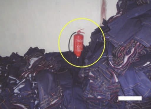
INTRODUCTION

       This manual is developed by the Accord on Fire and Building Safety to support factories in
       the implementation of fire protection measures.

       Fire protection is a fundamental Accord goal. The Accord is primarily concerned with the life
       safety aspects of fire protection. The keys to fire life safety are:

       • fire prevention

       • early warning of the fire

       • containment of the fire

       • safe exits.

       This manual addresses all of these aspects except fire prevention which is addressed in a
       separate document. This manual also deals only with existing buildings. The Accord has
       some different requirements for new construction, as there are different options available for
       achieving safety in a newly constructed building.

       Early warning of fire is achieved through automatic fire alarm systems. Automatic fire
       alarm systems are required in all garment factories. Fire alarms can be initiated
       automatically by smoke detectors or heat detectors, or manually by pull stations. The alarm
       then sounds by means of bells or horns in order to notify the occupants to evacuate the
       building.

       Containing the fire is achieved by creating fire compartments using fire resistant walls and
       floors. Fire barriers are required from floor to floor in multi-storey buildings, around certain
       rooms within the building, and to enclose exit stairwells. Sprinkler systems serve two
       functions: detecting the fire for immediate evacuation; and containing the fire at its source.

       Safe and efficient exiting is accomplished by providing necessary exits (at least two), and
       ensuring that the exits remain free of smoke and fire by requiring fire barriers around the exit
       stairs. Locks are not permitted on exits.

3|43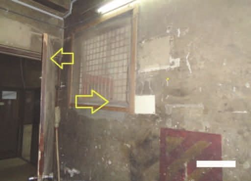
FIRE SEPARATIONS – FIRE COMPARTMENTS

       Fire separations are provided within buildings to limit the spread of fire. Certain rooms,
       areas, and occupancies in buildings are generally fire separated into fire compartments.
       These fire compartments limit fire spread for a specified period of time intended to allow
       persons to escape and to limit fire growth until the fire department extinguishes the fire.

       Consider a fire compartment to be a box. Most buildings have many fire compartments
       (boxes), which are situated side by side and on top of each other. Each fire compartment has
       walls, a floor and a ceiling. The walls are fire separations that limit the spread of fire
       horizontally from one fire compartment to an adjoining fire compartment. The top and
       bottom of each fire compartment are often referred to as floor assemblies when they separate
       one storey from another. The floor assemblies are fire separations that limit the spread of fire
       vertically from one fire compartment to another.

       Fire separations can be constructed of combustible or non-combustible elements or a
       combination of materials. For example, masonry walls and reinforced concrete floor slab
       assemblies are considered to be non-combustible. Due to the physical characteristics of the
       materials, they have substantial strength and will effectively limit the spread of fire provided
       the assembly has been properly constructed and maintained.

       The design and types of material used in the construction of a fire separation will determine
       its fire-resistance rating. The fire-resistance rating of a fire separation means the time in
       hours or fractions thereof that a material or assembly of materials will withstand the passage
       of flame and transmission of heat when exposed to fire under specified conditions of test and
       performance criteria.

       The design of the fire separation, the thickness and qualities of materials used and the
       manner of construction will determine the fire-resistance rating for the entire assembly.

       The fire resistance ratings of structural elements, building components or assemblies shall be
       determined in accordance with the test procedures outlined in ASTM E 119 or UL 263.

       Fire Resistance Rating of Common Construction Elements (From BNBC):

       Batteries                                                          Fire Resistance Rating

       1. Solid Walls
          A. 75 mm thick walls of clay bricks                             0.75 hour
          B. 125 mm thick walls of clay bricks                            1.5 hours
          C. 250 mm thick walls                                           5.0 hours

       2. RC Walls
          a. 150 mm thick RC wall                                         3.0 hours
          b. 200 mm thick RC wall                                         4.0 hours
          c. 250 mm thick RC walls                                        5.0 hours
          d. 300 mm thick RC walls                                        6.0 hours

       3. RC Slabs
          a. 100 mm RC slabs with 13 mm cover over reinforcement          1.0 hour
          b. 150 mm RC slabs with 19 mm cover over reinforcement          2.5 hours
          c. 200 mm RC slabs with 19 mm cover over reinforcement          3.75 hours
          d. 250 mm RC slabs with 25 mm cover over reinforcement          5.0 hours

       4. RC Columns (1:2:4)
          a. 250 mm x 250 mm with 25 mm cover over reinforcement          3.0 hours
          b. 300 mm x 300 mm with 25 mm cover over reinforcement          4.0 hours
          c. 400 mm x 400 mm with 25 mm cover over reinforcement          6.0 hours
          d. 400 mm x 400 mm with 50 mm cover over reinforcement          8.0 hours

4|43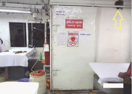
Floor assemblies and roof assemblies that have a required fire-resistance rating are
structurally supported by walls, columns or arches that have been designed and constructed
with the same fire-resistance rating as the assembly they support. This practice prevents
premature collapse of the structure under fire conditions resulting from the supporting
elements located below having a lower fire-resistance rating.
It is important to note that the fire-resistance rating of an assembly is based upon all of the
components of the assembly. The individual elements in themselves do not have a fire-
resistance rating.
Fire separations must be constructed as a continuous element to act as a barrier against the
spread of fire. A fire separation is required to be continuous and extend from one fire
separation to another or to an exterior wall or roof. Appropriate fire stopping is also essential
to retard the passage of smoke and flame, particularly at locations where a vertical fire
separation meets a floor or roof assembly.
For example, where a vertical fire separation that abuts a horizontal fire separation involving
a T-Bar ceiling assembly, the wall must extend through the concealed ceiling space and
terminate so that a smoke-tight joint is provided at the floor slab above.
Plumbing, wiring and mechanical services commonly pass through required fire separations.
The penetrations in the fire separations should be examined to determine if fire stopping has
been provided at the penetrations. These penetrations are often poorly sealed or neglected.
Ducts and ventilation openings that pass through a required fire separation must have a fire
damper installed at these penetrations. The fire damper is required in order to maintain the
integrity of the fire separation.
Special note: Openings and penetrations into and through an exit enclosure are
prohibited with the exception of required exit doors, sprinkler piping, standpipes, electrical
raceway for fire alarm equipment, and electrical conduit serving the exit enclosure only.
Shafts that are provided in a building to facilitate the installation of building services such as
mechanical, electrical and plumbing installations and facilities including elevators and
chutes must be enclosed by fire separations.
Some rooms or spaces require special consideration. These spaces are required to be
enclosed by fire separations having a specified fire-resistance rating. The enclosure confines
the fire to the area of fire origin. Areas requiring special attention include:
• Exit Stairs, elevator shafts and other vertical shafts
– 1 hour fire rating if building is less than 4 stories,
– 2 hour fire rating if building is 4 stories or greater
• Storage rooms – 1 hour fire rating,
• Boiler or furnace rooms – 1 hour fire rating,
• Generator rooms – 2 hour fire rating,
• Oil filled transformer rooms
– 2 hour fire rating unless in a high rise building
– 4 hour fire rating if in a high rise building
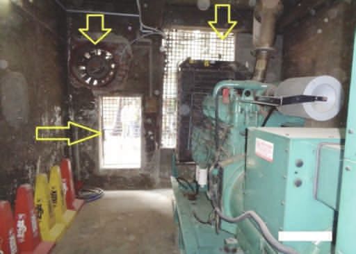
Example:
Picture 1
No proper
separation between
working floor and
fabric store has
been provided.
Picture 2
Boiler has been
installed near
production floor
without proper
separation.
5|43 1 2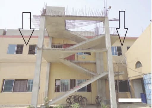
OPENINGS IN FIRE SEPARATIONS

                         Openings in fire separations are required to be protected with closures to limit the spread of
                         smoke and fire through the opening from one fire compartment to another. A closure means
                         a device or assembly for closing an opening through a fire separation. Examples of closures
                         are a door, a shutter, wired glass or glass block. All components, such as hardware, closing
                         devices, frames and anchors are included in the rated assembly.

                         Closures can consist of a variety of materials. The closures can be permanently mounted in
                         the fire separation and be fixed shut (i.e. wired glass window, glass blocks, etc.) or they may
                         be capable of being opened or closed when necessary (i.e., door, shutter, damper, etc.).

                         When closed, closures limit the spread of fire by virtue of their physical construction.
                         Closures in fire separations are required to have a specified fire rating. Closures and frames
                         usually have a permanent label attached to them identifying their listed fire rating.

                         REQUIRED RATINGS OF CLOSURES IN FIRE SEPARATIONS:
                         • 1.5-hour fire rated closure in a 2-hour fire separation,
                         • 1-hour fire rated closure in a 1-hour fire rated exit enclosure,
                         • 0.75-hour fire rated closure in a 1-hour fire separation other than exit enclosure.
                         • Fire windows shall conform to NFPA 257 or British, European, Chinese, or Indian standard
                           for fire window tests. The ASTM standard referenced in the BNBC Part 4 Section 1.5.5 has
                           been withdrawn.
                         • Fire door assemblies shall conform to NFPA 252, BS 476 Part 22, EN 1634-1, GB 12955-
                           2008, or IS 3614 Part II. The ASTM standard referenced in the BNBC Part 4 Section 1.5.4
                           has been withdrawn.

                         Example: Pictures show unsealed penetrations in different locations
          Picture 1
          Unsealed
Penetration through
                slab
          Picture 2
          Unsealed
        Penetration
          Picture 3
          Unsealed
Penetration through
   the rated wall of
        boiler room
          Picture 4
          Unsealed
penetration through

                          1                                                 2

                          3                                                 4

                         WHERE IMPROPERLY PROTECTED OPENINGS ARE SEEN IN MOST CASES:
                         In most cases unsealed penetrations and openings are found in the fire rated walls of
                         generator rooms, boiler rooms, storage areas and stairwells. Sometimes chutes are used to
                         transfer unfinished goods from higher floors to lower floors– vertical shafts must have a fire
                  6|43   resistance rating, and all openings must be protected by rated closures.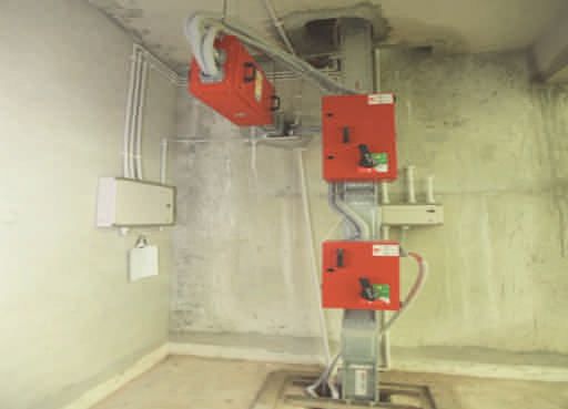
Example:
          Picture 1
Shows unprotected
         opening of
 generator room to
      the adjacent
  building or egress
               path.

          Picture 2
   Shows non-rated
   glass partitioned
 opening to the exit
enclosure and non-
rated wooden door
    has been used.

                          1                                                 2

                         Standard: Accord Standard Part-4 Section: 4.5.2.3, 4.5.4, 4.5.5, 4.5.7.3, 4.6 and BNBC Part-4
                         Section: 2.5.

                         MEANS OF EGRESS

                         A means of egress is a continuous and unobstructed way of exit travel from any point in a
                         building to a public way. A means of egress consists of three parts: exit access, exit, and exit
                         discharge. Exit access is the path from any location within a building to an exit. An exit is
                         typically a door leading to the outside or, in a multi-story building, an enclosed exit stairway.
                         Exit discharge is the path from the exit to the public way. A public way is a space that is
                         permanently deeded and dedicated to public use, most often a street or lane.

                         BASIC REQUIREMENTS FOR MEANS OF EGRESS
                         For any storey with only two exits, the maximum occupant load should not exceed
                         500 people.

                         For any storey with only three exits, the maximum occupant load should not exceed
                         1000 people.

                         For rooms with more than 49 occupants, doors must swing in the direction of egress
                         (i.e. the doors must swing out of the room).

                         For areas with more than 49 occupants, doors should be equipped with panic hardware
                         (crash bars).

                         In buildings without automatic sprinkler protection, exits must be separated by at least 1⁄2
                         the diagonal dimension of the room. In buildings equipped throughout with automatic
                         sprinkler protection, exits in each room should be separated by at least 1/3 of the diagonal
                         dimension of the room. In other words, if the room has two exits, but they are very close to
                         each other, it only counts as one exit.For example, the diagonal dimension of a square, 50’ by
                         50’ room would be approximately 70 feet. In a sprinklered building, the exit doors in this
                         room would have to be separated by at least 23 feet. In an unsprinklered building, the exit
                         doors would have to be separated by at least 35 feet.

                         Exit doors should lead to an exit stair enclosure, or directly to the exterior of the building.
                         Egress routes should not pass through adjacent rooms, and should not pass through
                         hazardous areas (such as kitchens, storage rooms, loading docks, etc.). If there are questions
                         regarding egress through adjacent areas, they should be brought to our attention for
                         further evaluation.

                         Exit doors must not be equipped with locking hardware that would allow an occupant to be
                         locked inside the room or space. Exit doors should also not be equipped with secondary
                         locking devices, such as a deadbolt or slide bolt, etc. It should be possible to open any
                         designated exit door using a single motion, without the use of a key, tool, or special
                  7|43   knowledge.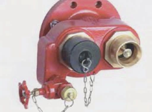
Each occupant must be provided with at least 4mm of egress width for exit doors. For
                        example, if the exit door is 32 inches wide, a maximum of 200 occupants could egress
                        through that door. Stairs require 8mm per person. The rules for minimum number of exits
                        still apply.

                        Occupant load is also limited by the size of the room, and depends on how the room is being
                        used. (See occupant load below.)

                        Minimum widths:

                         Structural Element                                         Fire Resistance Rating

                         Exit doors (existing)                                      0.8m (32 in.)

                         Exit doors (new)                                           1 m (40)

                         Aisles                                                     0.9m (36 in.)

                         Corridors                                                  1.1m (44 in.)

                         Stairs (existing)                                          0.9m (36 in.)

                         Stairs (new)                                               1.5m (59 in.)

                         Stair Landings (existing)                                  0.9m (36 in.)

                         Ramps                                                      1.1m (44 in.)

                        Standard: Accord Standard Part 6 section 6.5

                        EXTERIOR/EXTERNAL EXIT STAIR

                        Exterior exit stairs shall be separated from the building with the required ratings. If the exit
                        stair connect three or fewer stories, the stair shall be separated from the building with 1-hr
                        rated construction and if it connect four or more stories then shall be separated from the
                        building with 2-hr rated construction.

                        The rating of the exterior wall shall extend 3.05 m (10 ft) beyond the ends of the stair
                        structure.

                        Example:
           Picture
shows an external
         stair with
unprotected glass
window of left and
       right side.

                        Standard: Accord Standard Part 6 section 6.5, 6.6 and 6.8

                 8|43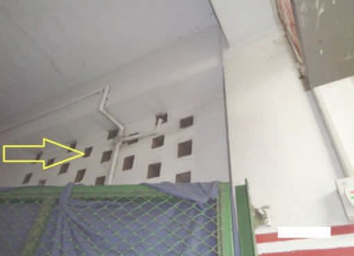
EXIT PASSAGEWAYS

                         General: An exit passageway is an exit component that is separated from other interior
                         spaces of a building or structure by fire resistance-rated construction and opening protection,
                         and provides for a protected path of egress in a horizontal direction to the exit discharge or
                         the public way.

                         Use: Exit passageways shall be considered an extension of the stairs and shall not be used for
                         any other purpose.

                         Construction Rating: Exit passageways shall have walls, ceilings, and floors that meet the
                         same rating requirement as the exit that is being served and shall not be less than 1-hr fire-
                         resistance rated construction.

                         Termination: Exit passageways shall terminate at an exit discharge.

                         OCCUPANT LOAD

                         The occupant load, in number of persons for whom means of egress are required, shall be
                         determined on the basis of the occupant load factors in BNBC Part4 Section 3.5.1 that are
                         characteristic for the use of the space or the maximum probable population of the space,
                         whichever is greater.

                         THE OCCUPANT LOAD FACTORS FROM THE BNBC ARE AS FOLLOWS:
                         • RMG (G1 & G2) factories shall have a calculated occupant load of 2.3m2 per occupant
                           (25ft2 per occupant). This occupant load factor is permitted to be increased or decreased
                           based on the actual number of occupants.
                         • Assembly (E) with tables and chairs: 1.5m2 per occupant (16ft2per occupant) net
                         • Assembly without fixed seats: 0.7m2per occupant (7ft2per occupant) net
                         • Offices(F): 10m2per occupant (100ft2per occupant) gross
                         • Other Industrial (G): 10m2per occupant (100ft2per occupant) gross
                         • Storage (H): 30m2per occupant (300ft2per occupant) gross
                         • Hazardous (J): 10m2per occupant (100ft2per occupant) gross

                         Standard: Accord Standard Part 6 section 6.4

                         TRAVEL DISTANCE

                         The maximum travel distance to reach an exit from any point in the building shall not exceed
                         45 meters unless the following requirements can be met:

            Picture
       shows travel
 distance (A-F, B-E,
      C-F, D-E) from
different locations.

                  9|43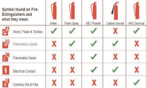
Travel distance limitations for G2 (RMG factories) shall be increased to 60 m (200 ft) where
        a complete automatic fire detection system, portable fire extinguishers, and standpipe system
        are provided in accordance with this Standard.

        Travel distance limitations for G2 (RMG factories) shall be increased to 122 m (400 ft) where
        a complete automatic sprinkler system, automatic fire alarm system, and portable fire
        extinguishers are provided in accordance with this Standard.

        Standard: Accord Standard Part 6 Section 6.13

        FIRE ALARM AND DETECTION SYSTEM

        All garment factories require an automatic fire alarm system that activates the alarm and
        occupant notification devices by manual or automatic initiating devices (e.g. smoke detector,
        heat detector, sprinkler water flow) in the event of fire.

        When complete automatic sprinkler protection is provided throughout a floor with water
        flow devices designed to initiate the alarm notification, smoke and fire detection devices can
        be eliminated throughout that floor.

        Basic components of a fire alarm system: the following is a list of the basic components that
        can be installed together to make up a typical fire alarm system:

         Alarm Initiation Devices                         /PUJůDBUJPO"QQMJBODFT

         r.BOVBM'JSF"MBSN#PYFT                      r#FMMT
         r8BUFSŰPX*OJUJBUJOH%FWJDFT)FBU            r)PSOT
           Detectors                                      r4QFBLFST
         r4NPLF%FUFDUPST                               r4JSFOT
         r3BEJBOU&OFSHZ4FOTJOH'JSF%FUFDUPST         r4USPCFT
         r0UIFS'JSF%FUFDUPST                           r$PNCJOBUJPOVOJUT

         Fire Alarm Control Units                         Batteries

         r$POWFOUJPOBMůSFBMBSNTZTUFNT                r4UBOECZ1PXFS
         r"EESFTTBCMFůSFBMBSNTZTUFNT
         r"OOVODJBUPSQBOFM

         Cables

         r.JOJNVNDPSFNN'JSFSFTJTUBOU'1DBCMFTGPS%FUFDUPSTBOE.JOJNVN
           2-core- 2.5mm2 FR/FP 200 Cables for NAC Circuit.

        Where Required: Automatic fire alarm and detection systems shall be installed throughout
        all new and existing garment factories.

        Installation requirements: All installation and design requirements outlined in BNBC Part
        4 Section 4.4 shall be supplemented by the requirements of NFPA 72.

        Documentation: Installation of new fire alarm and detection systems shall be required to
        provide shop drawings as outlined in NFPA 72.

        Documentation Review: All fire alarm installations shall be submitted to the Chief Safety
10|43   Inspector for review prior to commencement of installation.
Picture
shows examples of
BVUPNBUJDůSF
alarm and
detection systems
Smoke Detector Heat Detector
Manual Fire Alarm Call Point Fire Alarm Control Panel
Audible Notification Device Visual Notification Device
Acceptance testing: Testing of the installation shall be conducted in accordance with
NFPA 72 acceptance testing requirements. Documentation of all testing shall be submitted
for review by the Chief Safety Inspector. A final inspection and testing of the installation shall
be witnessed by the Chief Safety Inspector or designate.
Evacuation: Automatic alarm evacuation shall be provided upon initiation of any of the
following: manual alarm box, water flow alarm, or two or more automatic smoke or fire
detection devices. Notification shall be provided throughout the building for total evacuation.
Existing partial evacuation systems shall be replaced.
Monitoring: Until that time that a central station monitoring service or direct connection to
the Fire Service and Civil Defense can be set up, a person shall be assigned to contact the fire
department in the event of fire alarm activation. An annunciator shall be located in a
constantly attended location to alert this person.
11|43STANDPIPE SYSTEM
A stand pipe consists of rigid water piping which is built into buildings in a vertical position
to which fire hoses can be connected, allowing manual application of water to the fire. Within
the context of a building, a standpipe serves the same purpose as a fire hydrant.
Picture 1
shows 65mm
(Class I) standpipe
Picture 2
shows 40mm
(Class II) standpipe
connection
Picture 3
shows 65mm inlet
connections for Fire
Department.
1 2 3
Where Required: Standpipe systems shall be installed throughout all new and existing
buildings and structures where the highest occupied floor is more than 10 m (33 ft) above
grade or more than 10 m (33 ft) below grade.
Location of hose connections:
• Class I standpipe hose connections (65 mm) shall be located in all required stairwells at
each floor level including occupiable roofs.
• Class II standpipe hose connections (40 mm) shall not be required if the building is
protected with automatic sprinklers.
Installation requirements: All installation and design requirements outlined in BNBC Part
4 Chapter 4 for combined standpipe and automatic sprinkler systems shall be replaced by the
requirements of NFPA 14 with a minimum pressure of 450 kPa (65 psi) at the hydraulically
most remote hose connection. Standalone standpipe systems shall meet the BNBC
requirements with a minimum 450 kPa (65 psi) pressure at the hydraulically most remote
hose connection, or NFPA 14.
Documentation: Installation of new combined standpipe and sprinkler systems shall be
required to provide shop drawings and hydraulic calculations as outlined in NFPA 14. These
drawings shall include all details as outlined in NFPA 14.
Documentation Review: All standpipe system installations shall be submitted for review to
the Chief Safety Inspector prior to commencement of installation.
Acceptance testing: Testing of the installation shall be conducted in accordance with
NFPA 14 acceptance testing requirements. Documentation of all testing shall be submitted
for review by the Chief Safety Inspector. Final inspection and testing of the installation shall
be witnessed by the Chief Safety Inspector or designate.
Fire department connections: Fire department (Siamese) inlet connections shall be
provided to allow fire department pumper equipment to supplement the fire protection
systems. Fire department outlet connections shall be provided to allow fire department
pumper vehicles to draw water from ground-level or underground water storage tanks.
Connections shall match the Fire Service and Civil Defense hose thread standard.
12|43SPRINKLER SYSTEM
A fi re sprinkler system is an active fire protection measure, consisting of a water supply
system, providing adequate pressure and flow rate to a water distribution piping system,
onto which fire sprinklers are connected.
Where Required: Automatic sprinkler protection shall be installed throughout all portions
of new and existing high-rise buildings with an occupiable floor greater than 23 m (75 ft)
above the finished grade.
Existing buildings greater than 2 stories with nonrated construction shall not exceed 2000
m2 (22,000 sq. ft.) per floor unless automatic sprinkler protection is provided throughout.
Fire Pump: Fire pump design and installation shall be as per NFPA 20. The fire pump
capacity shall be determined by the hydraulic calculation. One duty pump and one standby
pump shall be installed. Jockey pump can be installed to overcome pressure losses due to
leakages. Pressure Relief Valve, Test valves, OS&Y Gate Valves, Non Return Valves and
Alarm check Valves are some of the valves required with the pump assembly.
Piping: Minimum wall thickness of steel pipes shall be in accordance with NFPA 13.
Zone Control Valves shall be installed in every floor or zone. A zone control valve consists
of i) Butterfly Valve, ii) Flow Switch and iii) Test and Drain. The flow switch and Butterfly
valve shall be interfaced with Fire Alarm System.
Sprinklers: Sprinkler orientation (Upright, Pendent, Sidewall etc), Sprinkler K factor,
Temperature rating of sprinklers and response type are important factors for sprinkler
selection in different hazards and commodities.
Picture
Different types of
Sprinkler Head
Conventional Upright Pendent
Horizontal sidewall
Vertical Sidewall Recessed Pendant
Recessed Pendent Concealed Horizontal Sidewall Concealed Pendent
RMG industries are considered as G2, Moderate Hazard Industrial Occupancy and as per NFPA
13|43 13 (2013) - A.5.3.2Ordinary Hazard Group II.Picture
shows typical
section of a
building, the highest
occupied floor level
of this building is
23m (75 ft.) above
ůOJTIFEHSBEF
Hence automatic
sprinkler system is
required.
Installation requirements: All installation and design requirements outlined in BNBC Part
4 Chapter 4 shall be replaced by the requirements of NFPA 13. Pipe schedules shall not be
used to size pipe. All systems shall be hydraulically calculated to meet the required NFPA 13
design requirements.
Documentation: Installation of new automatic sprinkler systems shall be required to
provide shop drawings and hydraulic calculations as outlined in NFPA 13. These drawings
shall include all details as outlined in NFPA 13.
Documentation Review: All sprinkler system installations shall be submitted for review to
the Chief Safety Inspector.
Acceptance testing: Testing of the installation shall be conducted in accordance with
NFPA 13 acceptance testing requirements. Documentation of all testing shall be submitted
for review to the Chief Safety Inspector. Final inspection and testing of the installation shall
be witnessed by the Chief Safety Inspector or designate.
Valves: All valves controlling automatic sprinkler systems, fire pumps, and water supply
systems shall be electrically supervised by a listed fire alarm system control unit.
Alarms: Activation of the water flow shall activate the fire alarm system.
Testing and maintenance: Automatic sprinkler systems shall be tested and maintained in
accordance with NFPA 25.
Storage clearance: All storage shall be maintained with a 460 mm (18 in.) minimum
clearance from the top of storage to the sprinkler deflector.
Racks: Unless in-rack automatic sprinklers have been designed and installed, solid shelf
racking shall not be used. A minimum of 50% openings in shelving material shall be
considered open shelves. See NFPA 13 for further clarification.
Shelves: Shelving units not greater than 760 mm (30 in.) deep can have solid shelves. Back
to back solid shelf units not greater than 760 mm (30 in.) deep each with a solid vertical
barrier can have solid shelves. See NFPA 13 for further clarification.
Aisles: Minimum aisles shall be maintained free of storage in accordance with NFPA 13
14|43 based on the design criteria used for the sprinkler system.PORTABLE FIRE EXTINGUISHERS
Portable fire extinguishers shall be installed throughout all new and existing facilities in
accordance with BNBC Part 4 Section 4.10 and NFPA 10.
Spacing: Extinguishers shall be placed so that maximum travel distance to the nearest unit
shall not exceed 30 m (100 ft).
Mounting height:
a. Fire extinguishers having a gross weight not exceeding 18.14 kg (40 lb) shall be installed so
that the top of the fire extinguisher is not more than 1.53 m (5 ft) above the floor (NFPA 10
6.1.3.8).
b. Fire extinguishers having a gross weight greater than 18.14 kg (40 lb) (except wheeled
types) shall be installed so that the top of the fire extinguisher is not more than 1.07 m
(3_ ft) above the floor (NFPA 10 6.1.3.8).
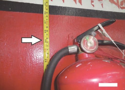
Picture 1
TIPXT ůSF
extinguisher having
a gross weight not
exceeding 18.14 kg
(40 lb) but the
mounting height of
this extinguisher is 65
in. above the floor
level which is not
complying with the
ACCORD Standard.
Picture 2
TIPXTůSF
extinguisher placed
in such a place
which is not easily 1 2
accessible and also
OPJEFOUJůDBUJPO
Signs: Fire extinguisher identification signs shall be posted near a fire extinguisher to easily
sign or marking
posted near identify the location (e.g. if the Extinguisher is on a large pole, the sign would generally be at
extinguisher by the top of the pole so it can be seen from a distance).
which it could be
FBTJMZJEFOUJůFE
Placement: The portable fire extinguisher shall be placed near the path of exit travel and it
shall be easily accessible.
Picture 3
guidelines for
selections of
QPSUBCMFůSF
extinguishers.
3
Inspection, Testing and Maintenance: Fire extinguishers shall be inspected, tested, and
maintained in accordance with NFPA 10.
15|43APPENDIX 16|43
APPENDIX A (FREQUENTLY ASKED QUESTION)

         1. Must fire exit doors be kept open?

        Answer:
        No, fire doors are normally closed. Fire doors must be equipped with automatic closers and
        latches. If fire doors are required to beheld open for functional reasons, magnetic hold open
        devices may be provided. Magnetic hold open devices must release upon fire alarm. Wedges
        under the door or tying the door open are not permitted under any circumstances.

         2. During factory operation the fire doors should be opened or closed?

        Answer:
        Closed is preferred, but, if the factory wants to keep the door open, a magnetic hold open
        device maybe used which shall be interfaced with fire alarm system in such a way that in case
        of fire the door will be closed automatically getting the signal from Fire Alarm Panel. Wedges
        under the door or tying the door open are not permitted under any circumstances.

         3. Are basket type ladders required to be installed?

        Answer:
        No. Sufficient protected exit stairways are required in all factory buildings.

         4. Is there any specific reference on the fire door approval authority? What are the
         credible organizations that can supply certified fire doors as per Accord
         requirements?

        Answer:
        1. Doors shall be tested by a UL, FM or other recognized third party complying with the
           standards mentioned in Accord standard- NFPA 252; BS 476 part 22, EN 1364-1, GB
           12955-2008 etc. The standard shall be mentioned in the certificate provided by the
           testing laboratory and the door must be manufactured in accordance with the
           certification agency terms.
        2. The fire doors and frames shall have permanent labeling with the information of
           themanufacturer, model number, the listing agency and the rating.
        3. If the doors contain glass, it must be tested and have the same fire rating of the door.
        4. The test certificate shall mention the testing of the door with glass inserts if applicable.
        5. The door hardware will also be listed as fire rated or tested as part of the assembly.

        A third party certification does the following:
        1. Tests the fire door to the approved standard.
        2. Helps to ensure the durability and reliability of the product.
        3. Verifies the manufacturing facility, audits the quality control procedures and the
            manufacturer’s ability to produce the product as tested.
        4. Provides a marking procedure used to identify the product in the field.
        [Reference: Accord Standard Part 4, Section 4.5.4]

         5. If the width of an exit opening is large (aprx. 8 to 9 feet) then what measures need
         to be taken? How are fire doors installed for those exits?

        Answer:
        Two or three fire rated doors may be needed in this circumstance. Installation procedure
        shall follow the manufacturer’s recommendations.

         6. Is a sprinkler system required to be installed on all floors of a high rise building?

        Answer:
        Yes. If the floor level of the highest occupiablefloor is equal to or greater than 23 meters (75
        feet) then a sprinkler system is required throughout the building as per NFPA13.

        [Reference: Accord Standard Part 5, Section 5.3]
17|43
7. Do all of the exit doors need to have panic hardware (push bars)?
Answer:
Yes. All fire doors to be push bar type as per the Accord standard where the floor or room
contains more than 50 occupants.
[Reference: Accord Standard Part 4, Section 4.5.4]
8. Are Alliance Building, Fire and Electrical safety reports accepted by the ACCORD?
Answer:
The Accord requires independent inspections carried out under the direction of the Accord
Chief Safety Inspector. However, the Accord has developed a policy allowing the Chief Safety
Inspector to accept Alliance inspections in most circumstances.
9. Are electrical distribution panel boards/boxes acceptable at the exit doors?
Answer:
They are not acceptable in exit stairwell enclosures.
10. If the boiler is located outside of the factory building, is a fire resistive wall
required?
Answer:
Any room or space housing boilers or other heat producing equipment shall be separated
from other spaces by a minimum 1 hour construction or by a minimum spatial separation of
3 m (10 ft) where located exterior to the building.
[Reference: Accord Standard Part 3, Section 3.4.2.1.2; BNBC Table 3.2.2]
11. Do electrical rooms requirea fire resistive door and wall?
Answer:
Yes, for electrical rooms the wall should be of minimum 2 hour fire rated construction. A 1.5
hour fire rated door is required.
12. Do fire doors need to be installed at the roof level?
Answer:
Usually not, but a swing type door is required, and if the roof is occupied then it may need to
be a fire door.
[Reference: Accord Standard Part6, Section 6.6.4]
13. Are mini boilers allowed to be installeded in the production floor close to the
workers?
Answer:
Mini boilersare allowed to be installed in the production floor insidea separate room. The
wall construction should be 1 hour fire rated and the openings should be protected by 0.75
hour fire rated assemblies. Structural column strength should be checked before installation.
14. Are boilers less than 500KG permitted to be installed in the upper floors?
Answer:
There is no problem from a fire safety point of view as long as the boiler room is separated by
fire rated construction. However, structural column strength should be checked before
installation to ensure that the floor can take the load.
15. Do sprinkler systems need to be operational 24hrs a day?
Answer:
The sprinkler system is an automatic system and shall be active at all times.
[Reference: Accord Standard Part 5, Section 5.3]
18|4315. Do sprinkler systems need to be operational 24hrs a day?
Answer:
The sprinkler system is an automatic system and shall be active at all times.
[Reference: Accord Standard Part 5, Section 5.3]
16. Are steel staircases acceptable since they have high heat and electricity
conductivity?
Answer:
Yes, they are acceptable, although they must be properly designed for structural integrity
and exit requirements.
17. A factory has 3 exit doors and they want to install another one that will be an
external steel staircase. Is that acceptable?
Answer:
Yes, it is acceptable although they must be properly designed for structural integrity and
exit requirements.
18. If the generator and substation are in the same room, must they be in separate
fire compartments?
Answer:
The standard requires a fire separation, but in existing factories we are using judgment as to
the feasibility of separating them. The combined area must be fire separated from the rest
of the building.
[Reference: Accord Standard Part 3, Section 3.4.2.1.3 & 3.4.2.1.4]
19. Can a factory do the fire door testing by themselves?
Answer:
No, the factory cannot do the test themselves. The door must be certified by an acceptable
certification company.
[Reference: Accord Standard Part 4, Section 4.5.4]
20. If a factory is not in a high-rise building, is a sprinkler system required in the
storage warehouse?
Answer:
No. If the building is not a high-rise, a sprinkler system will not be required by the Accord.
However, the storage or warehouse shall be separated by fire rated construction. Fire
service rules may require a sprinkler system in warehouse areas.
Where a separate storage room is not feasible, provide defined storage areas and limit the
storage arrangement as follows:
- Maximum height of 2.4m and maximum area of 23m2
- If sprinkler protected: maximum height of 3.66m and maximum area of 93m2
Separate the areas of unenclosed combustible storage by minimum clear distance of 3m.
[Reference: Accord Standard Part 3, Section 3.4.2.1.6]
21. Is a push bar door required for all exits?
Answer:
A push bar is required at all exit doors where the occupant load is more than 50.
[Reference: Accord Standard Part6, Section 6.8]
19|4322. When does the timeline for taking corrective action begin? From the date of
inspection, or from the date the report is received?
Answer:
The timeline for the corrective action plan begins from the date that the report is received.
23. Are fire doors required in prefabricated tin shed factories?
Answer:
If the shed consist of a ground floor only, exterior exit doors are not required to have a fire
protection rating. However, all exit doors must be swing type, opening outward, and shall
be installed with panic bars.Please note: rated fire doors are required in fire separations.
Exterior walls are typically not fire separations.
24. Since the generator room is already outside the factory, why should we need to
install fire doors?
Answer:
Generator sets shall be separated from all other occupancy areas by a minimum 2 hour
construction or by a minimum spatial separation of 3 m (10 ft) where located exterior to the
building. Fuel tanks shall be limited to a maximum 2500 L (660 gal) when located in a
building with other occupancies. Exhaust shall be in accordance with NFPA 37. All exhaust
systems shall discharge to the exterior of the building in a safe location.
[Reference: Accord Standard Part 3, Section 3.4.2.1.2.1]
25. If a staircase is directly connected to the outside with open ventilation, can we
do without the fire doors?
Answer:
No, fire doors are required to protect the staircase from a potential fire in the floor area.
20|43APPENDIX B (FIRE SPRINKLER SYSTEM INSPECTION CHECK LIST)
To be completed by the Inspector at the time of Inspection
Attach additional sheets, data or calculation as necessary to provide a complete
record
FACTORY INFORMATION
Factory Name: _____________________________________________________
Address: _________________________________________________________
Representative Name: ________________________________________________
Designation: ______________________________________________________
Phone: _________________ Fax: _______________
E-mail:_________________
INSTALLATION, SERVICE AND TESTING CONTRACTOR INFORMATION
Contractor Name: ___________________________________________________
Address: _________________________________________________________
Inspector or Tester Name: _____________________________________________
Qualification of Inspector or Tester: ______________________________________
Phone: _________________ Fax: _______________
E-mail:_________________
A Contract for Inspection & testing in accordance with NFPA is in effect as of: ________
The Contract Expires: ________________Frequency of Test: __________________
WITNESS BY
Company Name: ____________________________________________________
Address: _________________________________________________________
Representative Name: ________________________________________________
Designation: ______________________________________________________
Phone: _________________ Fax: _______________
E-mail:_________________
21|43Inspection, Testing & Maintenance: Weekly Scope Action Taken
Sprinkler heads Visual Checking YES / NO
Sprinkler Piping Visual Checking YES / NO
Control Valves Inspection YES / NO
Pumper Connections (Fire Department pumper Inspection YES / NO
connections)
Inspection, Testing & Maintenance: Monthly Scope Action Taken
Physical damage of sprinkler heads Visual Inspection YES / NO
Corrosion or leaks of sprinkler piping Visual Inspection YES / NO
Post indicator control valves Testing YES / NO
Inspection, Testing & Maintenance: Quarterly Scope Action Taken
Waterflow devices Testing YES / NO
Visual Inspection
Valve supervisory devices Testing YES / NO
Visual Inspection
Supervisory signal devices (except valve supervisory Visual Inspection YES / NO
switches)
Priming water Testing YES / NO
Low air pressure alarms Testing YES / NO
Quick-opening devices Testing YES / NO
Main Drains Testing YES / NO
Inspection, Testing & Maintenance: Scope Action Taken
Semiannually
Supervisory Switches Testing YES / NO
Valve tamper alarm Testing YES / NO
22|43Inspection, Testing & Maintenance: Annually Scope Action Taken
Position (Control Valve) Checking YES / NO
Full flow Testing YES / NO
Pressure relief valves Testing YES / NO
Backflow Prevention Assemblies Testing YES / NO
Lubrication of Control Valves Maintenance YES / NO
Preaction/Deluge Valves- If Applicable Cleaning YES / NO
Hanger/seismic bracing Inspection YES / NO
1JQFBOEůUUJOHT Inspection YES / NO
23|43APPENDIX C (STANDPIPE SYSTEM INSPECTION CHECK LIST)
To be completed by the Inspector at the time of Inspection
Attach additional sheets, data or calculation as necessary to provide a complete
record
FACTORY INFORMATION
Factory Name: _____________________________________________________
Address: _________________________________________________________
Representative Name: ________________________________________________
Designation: ______________________________________________________
Phone: _________________ Fax: _______________
E-mail:_________________
INSTALLATION, SERVICE AND TESTING CONTRACTOR INFORMATION
Contractor Name: ___________________________________________________
Address: _________________________________________________________
Inspector or Tester Name: _____________________________________________
Qualification of Inspector or Tester: ______________________________________
Phone: _________________ Fax: _______________
E-mail:_________________
A Contract for Inspection & testing in accordance with NFPA is in effect as of: ________
The Contract Expires: ________________Frequency of Test: __________________
WITNESS BY
Company Name: ____________________________________________________
Address: _________________________________________________________
Representative Name: ________________________________________________
Designation: ______________________________________________________
Phone: _________________ Fax: _______________
E-mail:_________________
24|43Inspection, Testing & Maintenance: Weekly Scope Action Taken
Control Valve - (sealed) Inspection YES / NO
Gauges Inspection YES / NO
Inspection, Testing & Maintenance: Monthly Scope Action Taken
Control Valve - (locked) Inspection YES / NO
Control Valve - (tamper switches) Inspection YES / NO
Inspection, Testing & Maintenance: Quarterly Scope Action Taken
Fire Department Connection Inspection YES / NO
Maintenance
Hose Valves Inspection YES / NO
Low Air Pressure Alarms Testing YES / NO
Main Drain Testing YES / NO
Pressure Regulating Devices and Connections Inspection YES / NO
Waterflow Alarms Testing YES / NO
Inspection, Testing & Maintenance: Scope Action Taken
Semiannually
Control Valve – (tamper switches) Testing YES / NO
Inspection, Testing & Maintenance: Annually Scope Action Taken
Cabinet Inspection YES / NO
Fire Hose Inspection YES / NO
Testing
Hose Connections Maintenance YES / NO
Hose Connection/Pressure Regulating Devices Inspection YES / NO
Hose Nozzles Inspection YES / NO
Hose Racks Inspection YES / NO
Hose Storage Device Testing YES / NO
Main Drain Testing YES / NO
Piping Inspection YES / NO
25|43Pressure Reducing Valves Inspection YES / NO
Valves (all types) Maintenance YES / NO
Inspection, Testing & Maintenance: Annually Scope Action Taken
Flow Test Most Remote Hose Connection Testing YES / NO
Hydrostatic Test (dry systems or pipe) Testing YES / NO
Pressure Control Valve Testing YES / NO
Pressure Reducing Valve Testing YES / NO
26|43APPENDIX D (FIRE PUMP SYSTEM INSPECTION CHECK LIST)
To be completed by the Inspector at the time of Inspection
Attach additional sheets, data or calculation as necessary to provide a complete
record
FACTORY INFORMATION
Factory Name: _____________________________________________________
Address: _________________________________________________________
Representative Name: ________________________________________________
Designation: ______________________________________________________
Phone: _________________ Fax: _______________
E-mail:_________________
INSTALLATION, SERVICE AND TESTING CONTRACTOR INFORMATION
Contractor Name: ___________________________________________________
Address: _________________________________________________________
Inspector or Tester Name: _____________________________________________
Qualification of Inspector or Tester: ______________________________________
Phone: _________________ Fax: _______________
E-mail:_________________
A Contract for Inspection & testing in accordance with NFPA is in effect as of: __________
The Contract Expires: ________________Frequency of Test: ___________________
WITNESS BY
Company Name: ____________________________________________________
Address: _________________________________________________________
Representative Name: ________________________________________________
Designation: ______________________________________________________
Phone: _________________ Fax: _______________
E-mail:_________________
27|43Inspection, Testing & Scope Action Taken
Maintenance: Weekly
Tank level Visual Inspection YES / NO
Checking
Tank float switch Visual Inspection YES / NO
Testing
Solenoid valve operation Visual Inspection YES / NO
Testing
Water in system Checking YES / NO
Cleaning
Flexible hoses and connectors Visual Inspection YES / NO
Oil level Visual Inspection YES / NO
Checking
Lube oil heater Checking YES / NO
Level (Cooling system) Visual Inspection YES / NO
Checking
Diesel Adequate cooling water to heat Checking YES / NO
Engine exchanger
System
Water pump(s) Visual Inspection YES / NO
Condition of flexible hoses and Visual Inspection YES / NO
connections Checking
Jacket water heater Checking YES / NO
Leakage (Exhaust system) Visual Inspection YES / NO
Checking
Drain condensate trap Checking YES / NO
Electrolyte level (Battery system) Checking YES / NO
General inspection Visual Inspection YES / NO
Pump house, heating ventilating Visual Inspection YES / NO
louvers Checking
Inspection, Testing & Scope Action Taken
Maintenance: Monthly
Electrical
System Exercise isolating switch and circuit Visual Inspection YES / NO
breaker Checking
28|43Case exterior clean and dry (Battery Testing YES / NO
system)
4QFDJůDHSBWJUZPSTUBUFPGDIBSHF Visual Inspection YES / NO
Diesel (Battery system)
Engine
System Charger and charge rate (Battery Checking YES / NO
system)
Equalize charge (Battery system) Checking YES / NO
Circuit breakers or fuses (Electrical Visual Inspection YES / NO
system)
Inspection, Testing & Scope Action Taken
Maintenance: Quarterly
4USBJOFS ůMUFS PSEJSUMFH PS Cleaning YES / NO
combination thereof
Crankcase breather (Lubrication Visual Inspection YES / NO
system) Changing
Cleaning
Diesel Water strainer (Cooling system) Cleaning YES / NO
Engine
System *OTVMBUJPOBOEůSFIB[BSET &YIBVTU Visual Inspection YES / NO
system)
Terminals clean and tight (Battery Visual Inspection YES / NO
system) Checking
8JSFDIBůOHXIFSFTVCKFDUUP Visual Inspection YES / NO
movement (Electrical system) Checking
Inspection, Testing & Scope Action Taken
Maintenance: Semiannually
Electrical
System Operate manual starting means Testing YES / NO
(electrical)
Antifreeze protection level (Cooling Testing YES / NO
system)
Diesel Flexible exhaust section (Exhaust Visual Inspection YES / NO
Engine system)
System
Operation of safeties and alarms Checking YES / NO
(Electrical system) Testing
Boxes, panels, and cabinets Cleaning YES / NO
(Electrical system)
29|43Inspection, Testing & Scope Action Taken
Maintenance: Annually
Lubricate pump bearings Changing YES / NO
Pump Check pump shaft end play Checking YES / NO
System
Check accuracy of pressure Checking YES / NO
gauges and sensors Changing
Check pump coupling alignment Checking YES / NO
Mechanical Lubricate coupling Changing YES / NO
Transmission
Lubricate right-angle gear drive Changing YES / NO
Trip circuit breaker (if mechanism Testing YES / NO
provided)
Inspect and operate emergency Visual Inspection YES / NO
manual starting means (without Testing
power)
Electrical Tighten electrical connections as Checking YES / NO
System necessary
Lubricate mechanical moving parts Checking YES / NO
(excluding starters and relays)
Calibrate pressure switch settings Checking YES / NO
Grease motor bearings Changing YES / NO
Water and foreign material in tank Cleaning YES / NO
Tank vents and overflow piping Checking YES / NO
unobstructed Testing
Piping Visual Inspection YES / NO
Rod out heat exchanger Cleaning YES / NO
Inspect duct work, clean louvers Visual Inspection YES / NO
(combustion air) (Cooling system) Checking
Diesel Changing
Engine
System Excessive back pressure (Exhaust Testing YES / NO
system)
Exhaust system hangers and Visual Inspection YES / NO
supports (Exhaust system)
Clean terminals (Battery system) Cleaning YES / NO
Tighten control and power wiring Checking YES / NO
connections (Battery system)
30|43Inspection, Testing & Scope Action Taken
Diesel Maintenance: Annually
Engine
System Oil change Changing YES / NO
0JMůMUFS T Changing YES / NO
31|43APPENDIX E (FIRE ALARM AND DETECTION SYSTEM INSTALLATION
INSPECTION CHECK LIST)
To be completed by the Inspector at the time of Inspection
Attach additional sheets, data or calculation as necessary to provide a complete
record
FACTORY INFORMATION
Factory Name: _____________________________________________________
Address: _________________________________________________________
Representative Name: ________________________________________________
Designation: ______________________________________________________
Phone: _________________ Fax: _______________
E-mail:_________________
INSTALLATION, SERVICE AND TESTING CONTRACTOR INFORMATION
Contractor Name: ___________________________________________________
Address: _________________________________________________________
Inspector or Tester Name: _____________________________________________
Qualification of Inspector or Tester: ______________________________________
Phone: _________________ Fax: _______________
E-mail:_________________
A Contract for Inspection & testing in accordance with NFPA is in effect as of: __________
The Contract Expires: ________________Frequency of Test: ___________________
WITNESS BY
Company Name: ____________________________________________________
Address: _________________________________________________________
Representative Name: ________________________________________________
Designation: ______________________________________________________
Phone: _________________ Fax: _______________
E-mail:_________________
32|43MANUFACTURER INFORMATION
System Manufacturer: ___________________________________________________
Country of Origin: ______________________________________________________
Address: ____________________________________________________________
Local Agent (If any): ___________________________________________________
Local Agent’s Address: __________________________________________________
Local Agent’s Representative Name: _________________________________________
Designation: _________________________________________________________
Phone: _________________ Fax: _______________
E-mail:______________________
SYSTEM INFORMATION
Type of System: Conventional Addressable
Repeater Panel (Specify Location): __________________________________________
Number of Detectors: Smoke Detector: ___________________
Heat Detector: ____________________
Beam Detector: ____________________
Multi Sensor Detector: _______________
Others (Specify): __________________________________________
Pull Station: __________________________________________________________
Alarm Sounder (with/without) Flasher: _______________________________________
Horn/Chime/Strobe/Speaker: _____________________________________________
Others (Specify): ______________________________________________________
Battery- Manufacturer: _______________ Type: ____________
Nominal Voltage: __________ Amp/Hour Rating: __________________
Attach additional sheets as necessary to provide a complete record
33|43INSPECTION CHECKLIST
General Information Comments
Sl. No Description Yes No
01 A copy of the Fire Alarm installation
DFSUJůDBUFBOE3FDPSEPGDPNQMFUJPOJT
QSPQFSMZůMMFEPVUBOEBWBJMBCMFGSPNUIF
installer.
02 More than one contractor was responsible Yes No N/A
for installation of the Fire Alarm System
BOEFBDIDPOUSBDUPSIBTůMMFEPVUUIF'JSF
"MBSNJOTUBMMBUJPODFSUJůDBUFBOE3FDPSE
of completion.
03 A copy of the as-built Fire Alarm System
drawing signed by a competent body is
available on site.
04 An Owner’s Manual, a copy of the
Manufacturer’s instruction, written
sequence of operation are available on
site.
05 For Addressable System a list of each
device with the corresponding location is
provided. The device addressing shall
reflect actual room names or numbers
that are current to the building use.
06 For Addressable System a copy of the
TQFDJůDTPŦXBSFXJUITPŦXBSFSFWJTJPO
number, software update date available
on site
Fire Alarm Control Panel (FACP)
07 The dedicated 220V ac branch circuit for
UIFůSFBMBSNQBOFMJTMBCFMFE“Fire Alarm
Circuit” on the panel schedule of the
electrical panel and the actual circuit
breaker is colored RED as per NFPA72.
08 The dedicated 220V ac branch circuit
shall be mechanically protected (i.e.
breaker lock) as per NFPA72.
09 Fire Alarm Control Panel is grounded
properly by Earth Continuity Conductor.
(connection can be taken from electrical
panel board’s earth bus-bar)
10 The location of the dedicated 220V ac
branch circuit shall be permanently
NBSLFEJOTJEFUIFůSFBMBSNDPOUSPMQBOFM
as per NFPA72.
34|43You can also read