Formation of ribbed bedforms below shear margins and lobes of palaeo-ice streams - The Cryosphere
←
→
Page content transcription
If your browser does not render page correctly, please read the page content below
The Cryosphere, 15, 2889–2916, 2021
https://doi.org/10.5194/tc-15-2889-2021
© Author(s) 2021. This work is distributed under
the Creative Commons Attribution 4.0 License.

Formation of ribbed bedforms below shear margins and lobes of
palaeo-ice streams
Jean Vérité1 , Édouard Ravier1 , Olivier Bourgeois2 , Stéphane Pochat2 , Thomas Lelandais1 , Régis Mourgues1 ,
Christopher D. Clark3 , Paul Bessin1 , David Peigné1 , and Nigel Atkinson4
1 Laboratoire de Planétologie et Géodynamique, UMR 6112, CNRS, Le Mans Université,
Avenue Olivier Messiaen, 72085 Le Mans CEDEX 9, France
2 Laboratoire de Planétologie et Géodynamique, UMR 6112, CNRS, Université de Nantes,

2 rue de la Houssinière, BP 92208, 44322 Nantes CEDEX 3, France
3 Department of Geography, University of Sheffield, Sheffield, UK
4 Alberta Geological Survey, 4th Floor Twin Atria Building, 4999-98 Ave., Edmonton, AB, T6B 2X3, Canada

Correspondence: Jean Vérité (jean.verite@univ-lemans.fr)

Received: 11 November 2020 – Discussion started: 21 November 2020
Revised: 28 May 2021 – Accepted: 3 June 2021 – Published: 28 June 2021

Abstract. Conceptual ice stream land systems derived from          1   Introduction
geomorphological and sedimentological observations pro-
vide constraints on ice–meltwater–till–bedrock interactions
on palaeo-ice stream beds. Within these land systems, the          The dynamics of ice sheets is largely controlled by the activ-
spatial distribution and formation processes of ribbed bed-        ity of narrow corridors of fast-flowing ice, named ice streams
forms remain unclear. We explore the conditions under which        (Paterson, 1994). In Antarctica, 10 % of the ice sheet is cov-
these bedforms may develop and their spatial organization          ered by ice streams and 90 % of the ice sheet is estimated
with (i) an experimental model that reproduces the dynam-          to discharge through these corridors that flow at a few hun-
ics of ice streams and subglacial land systems and (ii) an         dreds of m yr−1 (Bamber et al., 2000). Studies on modern
analysis of the distribution of ribbed bedforms on selected        ice streams – through remote sensing, borehole observations
examples of palaeo-ice stream beds of the Laurentide Ice           and geophysical measurements – have improved our under-
Sheet. We find that a specific kind of ribbed bedform can de-      standing of the influence of ice streams on the mass balance
velop subglacially through soft-bed deformation, where the         of ice sheets. Many investigations highlight the role of lat-
ice flow undergoes lateral or longitudinal velocity gradients      eral shear margins and frontal lobes on the overall stress bal-
and the ice–bed interface is unlubricated; oblique ribbed bed-     ance of ice streams and the importance of imparted drag,
forms develop beneath lateral shear margins, whereas trans-        along with basal drag, in controlling flow speed and ice
verse ribbed bedforms develop below frontal lobes. We infer        stream width and length (Engelhardt et al., 1990; Goldstein
that (i) ribbed bedforms strike orthogonally to the compress-      et al., 1993; Echelmeyer et al., 1994; Patterson, 1997; Tu-
ing axis of the horizontal strain ellipse of the ice surface and   laczyk et al., 2000; Raymond et al., 2001; Kyrke-Smith et
(ii) their development reveals distinctive types of subglacial     al., 2014; Minchew and Joughin, 2020). A lack of knowl-
drainage patterns: linked cavities below lateral shear margins     edge remains however on the spatial and temporal evolution
and efficient meltwater channels below frontal lobes. These        of basal conditions beneath ice streams (e.g. distribution of
ribbed bedforms may act as convenient geomorphic mark-             basal shear stresses, meltwater drainage patterns) and on the
ers to reconstruct lateral and frontal margins, constrain ice      processes acting at the ice–bed interface during the formation
flow dynamics, and infer meltwater drainage characteristics        of subglacial bedforms. This is because basal investigations
of palaeo-ice streams.                                             into modern ice streams are restricted to punctual observa-
                                                                   tions. Palaeoglaciology aims to fill this gap by using the ge-
                                                                   omorphological and sedimentological records of former ice

Published by Copernicus Publications on behalf of the European Geosciences Union.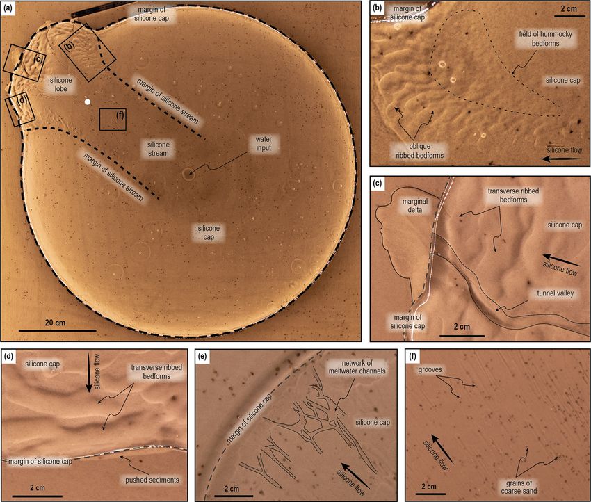
2890                 J. Vérité et al.: Formation of ribbed bedforms below shear margins and lobes of palaeo-ice streams

stream beds. Based on this approach, conceptual models of        structing spatial and temporal variations in the distribution
ice stream land systems characterized by either synchronous      of palaeo-ice streams, as well as understanding their geo-
or time-transgressive imprints have been developed (Dyke         morphic imprints across the landscape (Denton and Hughes,
and Morris, 1988; Kleman and Borgström, 1996; Clark and          1981; Patterson, 1997; Winsborrow et al., 2004; Margold et
Stokes, 2003).                                                   al., 2015). The areas where the ice starts to form channels in
   Even though general models of ice stream land systems         the upstream part of ice streams (i.e. onset areas) are char-
have now been established, the genesis of some landforms         acterized by slow ice flow and a large spectrum of flow ori-
in these land systems remains under debate, notably its rela-    entations due to the convergence of multiple tributaries. Ice
tion to ice dynamics and subglacial meltwater drainage. Af-      is then incorporated within narrow and well-defined trunks
ter mega-scale glacial lineations and drumlins, ribbed bed-      with high flow velocities (> 300 m yr−1 ; Clark and Stokes,
forms – subglacial periodic ridges that form transversely or     2003) and marked by swarms of streamlined bedforms par-
obliquely to the ice flow direction – potentially represent      allel to the ice flow direction (Fig. 1; mega-scale glacial lin-
some of the most conspicuous and ubiquitous landforms on         eations, flutes, drumlins and mega-grooves; Menzies, 1979;
palaeo-ice stream beds (Stokes, 2018). However, their distri-    Stokes and Clark, 2001, 2002a; Newton et al., 2018). Ice
bution is not clearly accommodated in current ice stream land    stream trunks are delimited by abrupt lateral shear mar-
system models (Dyke et al., 1992; Stokes and Clark, 2001;        gins, frequently underlined by continuous and linear shear
Stokes et al., 2007). Their formation is attributed to (i) bed   moraines (Dyke and Morris, 1988; Dyke et al., 1992; Stokes
deformation (e.g. Boulton, 1987; Hättestrand and Kleman,         and Clark, 2002b). Terminal zones of ice streams are charac-
1999; Lindén et al., 2008), (ii) meltwater flow (e.g. Shaw,      terized by either marine-based ice shelves and calving fronts
2002), or (iii) a combination of these (e.g. Fowler and Chap-    or land-based marginal lobation (Stokes and Clark, 2001). At
wanya, 2014). The formation of ribbed bedforms by most           the margin of terrestrially terminating ice streams, belts of
of these mechanisms involves spatio-temporal variations in       sediment ridges and mounds mimicking the lobe curvature
basal shear stress. Such variations are observed across lat-     can form in response to the ice lobe activity; stagnation pro-
eral shear margins (Raymond et al., 2001) and frontal lobe       duces hummocky moraines (e.g. Johnson and Clayton, 2003;
margins (Patterson, 1997) of ice streams. These margins          Ebert and Kleman, 2004), advances produce push moraines,
should therefore constitute preferential areas for the forma-    end moraines and overridden moraines (Totten, 1969; Boul-
tion of ribbed bedforms. However, a possible relation be-        ton, 1986; Evans and Hiemstra, 2005), and retreats produce
tween ribbed bedforms and ice stream margins has not been        recessional moraines (Chandler et al., 2016) (Fig. 1).
reported so far.                                                    Within this general model, the definition and genesis of
   In the following sections, we present a thorough review of    ribbed bedforms remains unclear. Different types and shapes
the literature on shape, size, spatial distribution and forma-   have been described; different theoretical models have been
tion of ribbed bedforms, and then we provide new constraints     proposed for their formation; various interpretations exist for
on the formation and distribution of ribbed bedforms beneath     their timing and conditions of formation compared to ice and
ice stream margins. For that purpose, we developed an ex-        subglacial drainage dynamics, and their spatial distribution
perimental model that reproduces the dynamics of ice stream      within glacial land systems is still debated.
margins together with the evolution of subglacial bedforms
and meltwater drainage. From remotely sensed images and          2.1   Types and shapes
topographic data, we also mapped ribbed bedforms below
lateral shear and frontal lobe margins of palaeo-ice streams     Ribbed bedforms are subglacial ridges of sediment, periodic,
of the Laurentide Ice Sheet (North America). By combin-          and transverse or oblique to the palaeo-ice flow (Fig. 1).
ing the experimental and geomorphological results, we pro-       We use the term “ribbed bedform” as a descriptive morpho-
pose an integrated model for the formation of ribbed bed-        logical term, without a genetic connotation, that embraces
forms associated with ice stream margins and discuss their       the following bedforms described in the literature: (i) Rogen
palaeoglaciological implications for the mapping of palaeo-      moraines (Lundqvist, 1969), (ii) ribbed moraines (Hughes,
ice streams and the reconstruction of past subglacial hydrol-    1964), (iii) mega-scale transverse bedforms (Greenwood
ogy and ice stream dynamics.                                     and Kleman, 2010) and (iv) intermediate-sized bedforms
                                                                 interpreted as the topographic expression of traction ribs
                                                                 (Sergienko and Hindmarsh, 2013; Stokes et al., 2016).
2   Ribbed bedforms in ice stream land systems                      Ribbed and Rogen moraines refer to sediment ridges origi-
                                                                 nally described during the 1960s in North America and in the
Glaciological, geomorphological and sedimentological stud-       lake Rogen (Sweden), respectively. These bedforms exhibit a
ies on terrestrially terminating and marine-terminating ice      range of possible shapes and orientations, from transverse to
streams have enabled the development of land system mod-         oblique, relative to the palaeo-ice flow direction (Aylsworth
els (Fig. 1a; Dyke and Morris, 1988; Kleman and Borgström,       and Shilts, 1989; Dunlop and Clark, 2006). They are hun-
1996; Clark and Stokes, 2003) which are critical for recon-      dreds of metres to a few kilometres in length, a few hundreds

The Cryosphere, 15, 2889–2916, 2021                                                 https://doi.org/10.5194/tc-15-2889-2021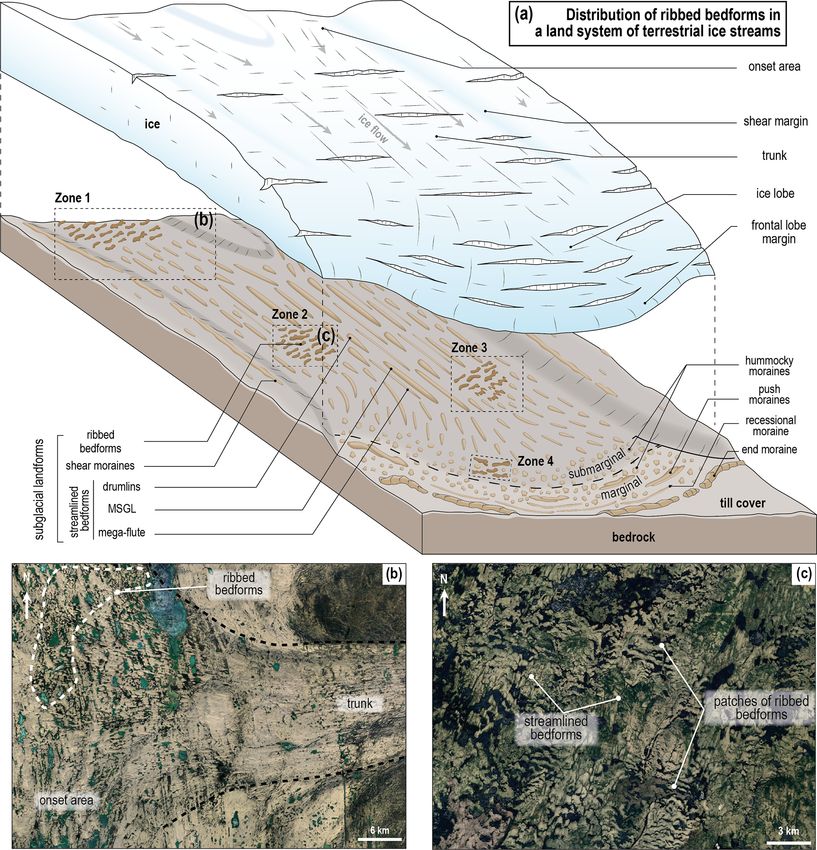
J. Vérité et al.: Formation of ribbed bedforms below shear margins and lobes of palaeo-ice streams                                      2891

Figure 1. (a) Distribution of ribbed bedforms, as currently envisaged, in an “ideal” isochronous land system of terrestrial palaeo-ice streams
(modified after Clark and Stokes, 2003). (b) Ribbed bedforms located in the cold-based onset area (Zone 1), upstream of the streamlined
bedforms, recording the warm-based trunk of an ice stream (Fisher Lake, Prince of Wales Island, Canada). (c) Patches of ribbed bedforms with
abrupt borders with surrounding streamlined bedforms (Zone 2; Lake Naococane, Canada). Also documented and shown in (a), although not
shown with specific examples, are progressive downstream transitions from ribbed bedforms to drumlins (Zone 3) and marginal relationships
between hummocky and ribbed bedforms (Zone 4) (© Landsat/Copernicus – © Google Earth).

https://doi.org/10.5194/tc-15-2889-2021                                                          The Cryosphere, 15, 2889–2916, 2021
2892                 J. Vérité et al.: Formation of ribbed bedforms below shear margins and lobes of palaeo-ice streams

of metres in width (l/w = 2.5) and tens of metres in height,      2.3    Theoretical models of formation
and their spacing is an order of magnitude lower than the ice
thickness (Paterson, 1972; Dunlop and Clark, 2006).               Theoretical models of formation invoke basal thermal con-
   Mega-scale transverse bedforms are 20 to 40 km in length,      ditions, meltwater flows or initial bed topography, to explain
3 to 6 km in width (l/w = 5.7) and 5 to 10 m in height            the shape and periodicity of ribbed bedforms. Four categories
(Greenwood and Kleman, 2010). They are depicted with a            of formation processes have been proposed: (i) deformation
perpendicular orientation relative to the ice flow direction,     or reshaping of pre-existing sedimentary mounds, such as
and their spacing is an order of magnitude higher than the        former streamlined or marginal landforms, by overriding ice
thickness of the overlying ice.                                   (Boulton, 1987; Lundqvist, 1989; Möller, 2006); (ii) frac-
   Intermediate-sized ribbed bedforms, interpreted as the         turing and extension of frozen beds along transitions from
morphological expression of traction ribs, are 1 to 6 km long,    warm-to-cold ice bases, where tensional stresses increase
0.4 to 2 km wide (l/w = 2.9) and 10 to 20 m high. They            (Hättestrand and Kleman, 1999; Sarala, 2006); (iii) sub-
are believed to form perpendicularly (90◦ ) to obliquely (20◦ )   glacial meltwater floods responsible for the formation of in-
relative to the ice flow direction and below ice thicknesses      verted erosional marks at the ice base, infilled by sediments
equal to or an order of magnitude lower than their spacing        (Shaw, 2002); and (iv) till deformation, in response to the
(Sergienko and Hindmarsh, 2013; Stokes et al., 2016).             flow of ice over bed heterogeneities resulting from varia-
   Crevasse-squeezed ridges also are subglacial periodic          tions in pore water pressure, the basal thermal regime and
ridges oriented transversally or obliquely to the ice flow        bed strength (Terzaghi, 1931; Shaw, 1979; Bouchard, 1989;
(Evans et al., 2015, 2016). However, their shapes and met-        Kamb, 1991; Tulaczyk et al., 2000; Lindén et al., 2008;
rics differ from those of the bedforms described above and        Stokes et al., 2008). The last process is consistent with phys-
are therefore not considered ribbed bedforms here.                ically based mathematical models demonstrating that ribbed
                                                                  bedforms naturally arise from wavy instabilities in the com-
2.2    Spatial distribution in ice stream land systems            bined flow of ice, basal meltwater and viscoplastic till (Hind-
                                                                  marsh, 1998a, b; Fowler, 2000; Schoof, 2007; Clark, 2010;
The palaeoglacial community agrees that some ribbed bed-          Chapwanya et al., 2011; Sergienko and Hindmarsh, 2013;
forms develop along rough ice–bed interfaces (frozen, unlu-       Fowler and Chapwanya, 2014; Fannon et al., 2017).
bricated or associated with stiff beds) with high basal shear        In conclusion, ribbed bedforms occur in a highly varied
stresses under slow-flowing portions of ice sheets. Ribbed        distribution within ice sheets and ice streams and multiple
bedforms are thus believed to be ubiquitous from the in-          hypotheses have been proposed for their formation. A size
ner, slow-moving regions of ice sheets (Aylsworth and Shilts,     and shape continuum has been suggested between ribbed,
1989; Dyke et al., 1992; Hättestrand and Kleman, 1999;            hummocky and streamlined bedforms, suggesting that these
Greenwood and Kleman, 2010; Stokes, 2018) up to the onset         subglacial bedforms could form in response to the same gov-
areas of ice streams at the transition between cold- and warm-    erning processes modulated by either ice flow velocity or ice
based ice, where the ice flow velocity increases downstream       flow duration (Aario, 1977; Rose, 1987; Dunlop and Clark,
(Fig. 1b – Zone 1; Bouchard, 1989; Dyke et al., 1992; Hättes-     2006; Stokes et al., 2013b; Ely et al., 2016; Fannon et al.,
trand and Kleman, 1999). They are thought to be less com-         2017). Moreover, ribbed bedforms are frequently overprinted
mon in ice stream trunks, where they would occur only as          by drumlins and embedded within polygenetic land systems,
isolated patches within a mosaic of sticky and slippery spots     corresponding to multiphase stories, which complicate their
associated with streamlined bedforms (Fig. 1c – zones 2, 3;       interpretation (Cowan, 1968; Aylsworth and Shilts, 1989;
Cowan, 1968; Aylsworth and Shilts, 1989; Bouchard, 1989;          Stokes et al., 2008). Previous studies emphasize the impor-
Dyke et al., 1992; Stokes and Clark, 2003; Stokes et al.,         tance of ribbed bedforms in the reconstruction of basal shear
2006a, 2008) and in submarginal areas, where they would be        stresses, ice–bed interactions, basal processes and ice dy-
associated with hummocky moraines within stagnant abla-           namics (Dyke and Morris, 1988; Alley, 1993; Stokes et al.,
tion complexes (Fig. 1 – Zone 4; Marich et al., 2005; Möller,     2008, 2016).
2006, 2010). To summarize, within an isochronous glacial
land system, ribbed bedforms are believed to form below
large-scale portions of slow-flowing ice (ice domes and stag-
                                                                  3     Methods
nant margins of ice sheets) and below localized patches of
slow ice within fast-flowing ice streams (sticky spots). Ac-      3.1    Analogue modelling
cording to this model, they would develop contemporarily
to streamlined bedforms, upstream (from ice domes to onset        The development of subglacial bedforms potentially involves
areas of ice streams), downstream (along marginal ablation        four mass transfer processes – erosion, transport, deposition
complexes) or laterally (within sticky spots).                    and deformation – that can occur simultaneously and inter-
                                                                  act beneath ice streams and four components – ice, water,
                                                                  till, and bedrock – that have complex and distinct rheolog-

The Cryosphere, 15, 2889–2916, 2021                                                  https://doi.org/10.5194/tc-15-2889-2021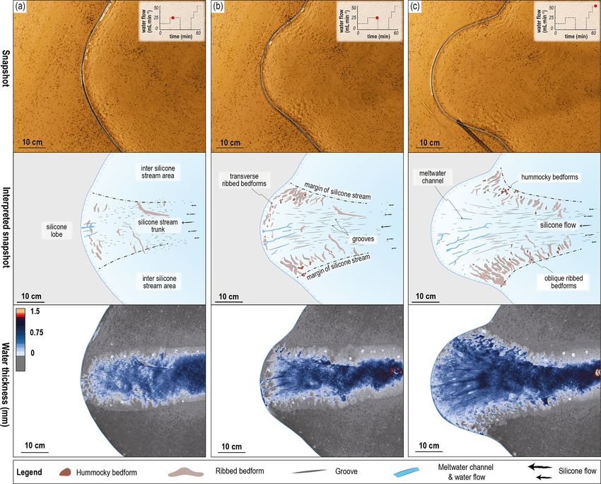
J. Vérité et al.: Formation of ribbed bedforms below shear margins and lobes of palaeo-ice streams                          2893

ical behaviours (Paterson, 1994). To understand the forma-        duration, were performed with different injection scenarios:
tion of ribbed bedforms, numerical models have been devel-        constant, binary and discontinuous (Table 1). Experimental
oped using naturally occurring typical values for the physical    scenarios were replicated at least three times in order to en-
properties of these components. In these models the growth        sure the reproducibility of the experimental setup. The exper-
of subglacial bedforms is based on (i) the development of         imental device is scaled according to the principles described
along-flow instabilities which creates wave-like bedforms re-     in Lelandais et al. (2016, 2018): to take into account the in-
sulting from infinitesimal perturbations at the surface of a      timate links between glacial dynamics, subglacial hydrology
deformable till layer (Hindmarsh, 1998a, b; Fowler, 2000;         and subglacial landform development, all physical quantities
Schoof, 2007; Chapwanya et al., 2011; Fowler and Chap-            in the experiment are defined so that the dimensionless ra-
wanya, 2014; Fannon et al., 2017) and (ii) till entrainment       tio between ice velocity and the incision rate of subglacial
and deposition resulting from till flux (driven by bed de-        erosional landforms has similar values in the model and in
formation and the ice pressure gradient) and lee-side cav-        nature. Lelandais et al. (2016, 2018) demonstrated that mod-
ity deposition (Barchyn et al., 2016). Three-dimensional nu-      els based on this scaling ratio are able to reproduce landforms
merical modelling of bedforms remains a challenging en-           representative of subglacial systems.
terprise. Their investigation is far from complete, mostly
because the involved components show drastically distinct         3.1.2   Monitoring of experiments and post-processing of
thermo-dependent and strain-rate-dependent rheologies and                 data
therefore temporal scales of activity (Paterson, 1994). To cir-
cumvent the challenge of numerically modelling these com-         The experimental device is equipped with white-light LEDs
plex interactions, Lelandais et al. (2016, 2018) developed        and UV LEDs, alternating every 15 s during an experiment.
a laboratory-based model capable of simultaneously sim-           An array of nine cameras acquires photographs (every 15 s)
ulating ice flow, subglacial hydrology and subglacial ero-        both in white light (all cameras) and in UV light (red cam-
sion/transport/sedimentation/deformation. This model con-         era only; Fig. 2a). The transparency of the injected water
tributed to better constrain the link between subglacial melt-    and the silicone cap in white light enables manual mapping
water drainage and the life cycle of ice streams, but sub-        of bedforms and reconstruction of digital elevation models
glacial bedforms were not included. We used the same ap-          (DEMs) of the bed surface from the white-light photographs,
proach with a new experimental setup, specifically designed       with a precision of ±0.1 mm, through a photogrammetric
to simulate the development of subglacial bedforms.               method developed by Lelandais et al. (2016). The morpho-
                                                                  metric properties of bedforms and drainage features (Fig. S1
3.1.1   Experimental setup                                        in the Supplement) are calculated from interpreted snapshots
                                                                  and DEMs. Maps of water distribution at the silicone–bed
The experimental device consists of a stainless-steel box,        interface are derived from the UV photographs, thanks to
5 cm high, 2 m × 2 m wide and surrounded by a gutter 5 cm         the fluorescence of the injected water. An automatic treat-
in width (Fig. 2a). A 5 cm thick bed, composed of sat-            ment of these images and a calibration with DEMs of the
urated fine sand (median grain size dmed = 100 µm; den-           sub-silicone bed allow fluorescence intensity to be converted
sity ρbulk = 2000 kg m−3 ; porosity 8s = 41 %; permeability       into water thickness. The pore water pressure is punctually
Ks = 10−4 m s−1 ), fills the box to simulate a soft, porous,      measured, 1.5 cm beneath the bed surface, with 12 pressure
permeable and erodible subglacial bed (Fig. 2b). Grains of        sensors (8 mm in diameter) distributed in two concentric cir-
coloured coarse sand (grain size d = 850 to 1250 µm), repre-      cles, 15 and 30 cm in radius, respectively, and centred on the
senting bedrock blocks, are sprinkled over the flat surface of    central water injector (Fig. 2a and b). The horizontal posi-
the bed. To simulate the ice sheet, a circular cap of viscous     tions of UV markers, 1 mm in diameter and placed with an
and transparent silicone putty (density ρsil = 967 kg m−3 ;       initial spacing of 5 cm on the silicone surface, are monitored
viscosity ηsil = 5 × 10⁴ Pa s−1 ), 3 cm thick in its centre and   with a time step of 90 s (Fig. 2b). Horizontal velocity (Vsurf )
90 cm in diameter, covers the bed. We inject a solution of        and deformation maps for the surface of the silicone cap are
mixed water and UV ink (bulk density ρw = 998 kg m−3 )            then calculated and interpolated from the temporal record of
through an injector located below the centre of the silicone      the marker displacements. The horizontal deformation of the
cap in order to produce water flow beneath the silicone and       silicone cap surface is quantified with two indicators, (i) the
highlight the flow pattern using UV light. The central in-        strain rate and orientation of the principal axes of the in-
jector, with a diameter of 8 mm, is placed 1.5 cm beneath         stantaneous strain ellipse (εextending > 0 and εcompressing < 0;
the surface of the bed and connected to a water pump. The         Ramsay and Huber, 1987) and (ii) the absolute magnitude of
injection is regulated by a flow meter (discharge Q = 0–          the horizontal shear strain rate (εshear ; Nye, 1959). Those in-
50 mL min−1 ) and is calculated to allow water circulation        dicators are computed for each triangle of a mesh, established
within the bed and along the silicone–bed interface, with a       by a Delaunay triangulation of all the UV markers (Fig. S2).
pressure of injected water exceeding the combined weights
of the bed and silicone layers. Fifteen experiments, 60 min in

https://doi.org/10.5194/tc-15-2889-2021                                                The Cryosphere, 15, 2889–2916, 2021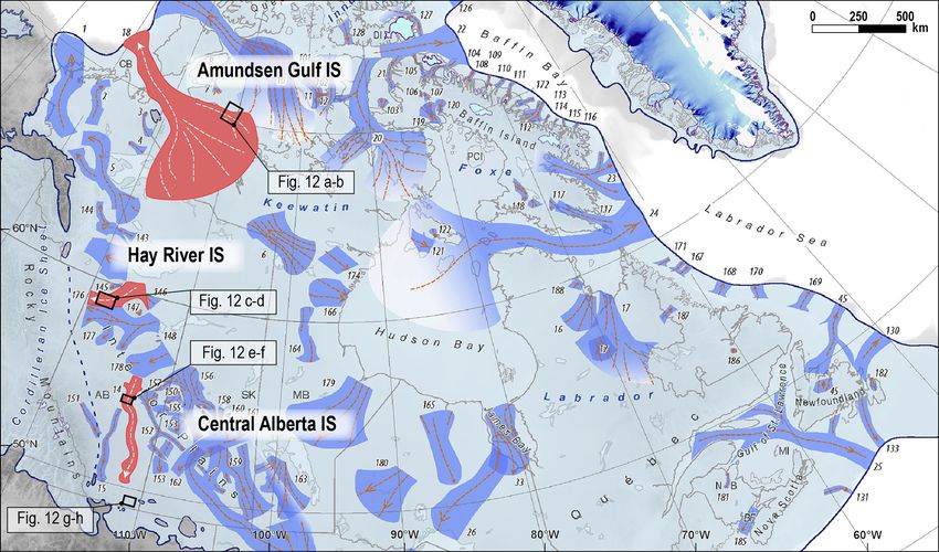
2894                   J. Vérité et al.: Formation of ribbed bedforms below shear margins and lobes of palaeo-ice streams

Figure 2. (a) Experimental model and monitoring apparatus. A cap, of transparent and viscous silicone putty, flows under its own weight
above a bed composed of water-saturated sand. We inject coloured water into the bed, through an injector located below the centre of
the silicone cap. We use a photographic acquisition device and pressure sensors to monitor the development of bedforms at the silicone–
bed interface, the silicone flow velocity, the water flow and the water pressure. (b) Transverse section of the model with the experimental
parameters.

3.1.3   Physics of silicone–water–bed interactions in the               experimental flow velocities we can simulate. Consequently,
        experiment                                                      spatial velocity gradients are expected to be smaller in the
                                                                        experiment than in nature, and the width of experimental lat-
                                                                        eral shear margins is overestimated compared to the width
The model is designed to explore the basic mechanical in-
                                                                        of experimental ice streams. The use of silicone putty also
teractions between a simplified water-routing system, a de-
                                                                        induces a major scaling limitation since the viscosity ratios
formable and erodible sedimentary bed, and an impermeable
                                                                        between the cap materials, either ice or silicone putty, and
viscous cover. The formation of sub-silicone bedforms in the
                                                                        the basal fluid, water in both cases, are different. The size
experiments involves interactions between the silicone putty,
                                                                        of erosive channelized features produced in the analogue
the injected water and the sand bed. Compared with ice, the
                                                                        model is thus overestimated compared to the dimensions of
silicone putty is Newtonian, isotropic and impermeable. Un-
                                                                        experimental ice streams. Internal production of meltwater,
der the experimental conditions (between 15–20 ◦ C and at
                                                                        complex spatial variations in subglacial hydrology, and lobe
atmospheric pressure), its viscosity is nearly independent of
                                                                        margin ablation and retreat are not reproducible either. The
temperature and the bed is constantly wet and saturated. Con-
                                                                        water-saturated sand bed is homogeneous and can deform by
sequently, temperature-dependent processes (shear heating,
                                                                        both localized and diffuse intergranular shearing; the flow of
heat softening, melting and freezing) and shear softening or
                                                                        both water and silicone can thus produce both internal de-
shear hardening related to the non-Newtonian behaviour or
                                                                        formation of the bed and erosion, transport and deposition of
the anisotropy of ice are not reproducible. Unlike ice, the
                                                                        grains at the bed–water or bed–silicone interface. The trans-
Newtonian silicone putty is thus unable to localize viscous
                                                                        port of sand grains through supra-silicone entrainment and
deformation when stress increases (in particular along lat-
                                                                        incorporation into basal silicone are not simulated.
eral shear margins) or to produce fractures in the range of

The Cryosphere, 15, 2889–2916, 2021                                                          https://doi.org/10.5194/tc-15-2889-2021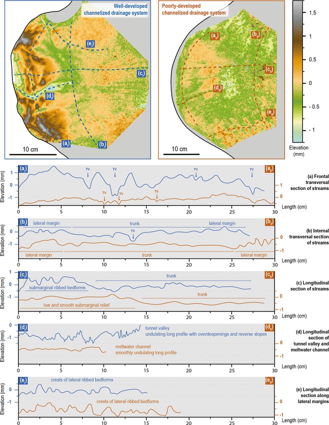
J. Vérité et al.: Formation of ribbed bedforms below shear margins and lobes of palaeo-ice streams                              2895

Table 1. Water injection scenarios and type of water drainage observed in each experiment.

      Experiment number    Water injection scenario                                            Channelized drainage beneath lobes
                                                                                              Well-developed    Poorly developed
      1                                                                                              ×
      2                                                                                              ×
      3                    Constant 25 mL min−1 (60 min)                                             ×
      4                                                                                              ×
      5                                                                                              ×
      6                                                                                              ×
      7                                                                                                                 ×
                           Constant 37.5 mL min−1 (60 min)
      8                                                                                              ×
      9                                                                                                                 ×
      10                                                                                             ×
      11                   Binary 25 mL min−1 (30 min) – 50 mL min−1 (30 min)                        ×
      12                                                                                             ×
      13                   Discontinuous 12.5 mL min−1 (15 min) – 25 mL min−1 (15 min) –             ×
      14                   0 mL min−1 (15 min) – 25 mL min−1 (5 min) –                                                  ×
      15                   37.5 mL min−1 (5 min) – 50 mL min−1 (5 min)                               ×

   The model, like all models, is not perfectly realistic since it     hillshade maps, we digitized ribbed bedforms, streamlined
reproduces neither a complete and scaled miniaturization of            bedforms indicative of predominant ice flow directions, and
nature nor all subglacial physical processes. Previous physi-          other landforms indicative of ice stream lateral and frontal
cal experiments have reproduced subglacial channelized fea-            margins at the scale of 1 : 50 000. The length (long axis),
tures (tunnel valleys) and marginal landforms (ice-contact             width (short axis) and orientation of ribbed bedforms com-
fans and outburst fans) and have suggested a close relation-           pared to the ice flow direction were extracted using the “Min-
ship between the development of tunnel valleys and the sta-            imum Bounding Geometry” tool in ArcGIS. The orientation
bilization of analogue ice streams (Lelandais et al., 2016,            values of ribbed bedforms and streamlined bedforms were
2018). It turns out that experimental models, although im-             compiled in rose diagrams for each selected region.
perfectly scaled, reproduce landforms visually conforming
to subglacial landforms, emphasizing the “unreasonable ef-
fectiveness” of analogue modelling (Paola et al., 2009).               4     Results

                                                                       4.1    Stream dynamics and development of ribbed
3.2   Mapping and morphometric analysis in palaeo-ice                         bedforms in the experiment
      stream land systems
                                                                       Without obvious dependence on the injection scenarios, the
To identify, map and characterize ribbed bedforms associ-              experiments listed in Table 1 produced two types of streams
ated with natural palaeo-ice stream margins, we compiled               and lobes related to two different types of water drainage net-
DEMs, hillshade maps and ice stream contours of the North              works beneath the silicone cap: (i) well-developed channel-
American Laurentide Ice Sheet (Margold et al., 2015) in a              ized drainage (n = 12 experiments) and (ii) poorly developed
geographic information system (GIS). Four distinct regions             channelized drainage (n = 3 experiments). In the following
(Fig. 3), covering a few thousand square kilometres, over-             section, we present the evolution of silicone stream dynam-
lapping the lateral shear and frontal lobe margins of three            ics and ribbed bedforms for one experiment representative
palaeo-ice stream beds were studied: (i) the Amundsen Gulf             of each kind: experiments 10 and 14, respectively (Table 1).
Ice Stream (21.8–12.9 ka cal BP), (ii) the Central Alberta Ice         In those two experiments, the water injection discharge was
Stream (20.5–17 ka cal BP) and (iii) the Hay River Ice Stream          doubled in stage 3 (Q = 50 mL min−1 ) compared to stages 1
(13.9–12.9 ka cal BP; Margold et al., 2018). We used a 15 m            and 2 (Q = 25 mL min−1 ).
lidar bare-earth DEM supplied by the Alberta Geological                   In both experiments, when water injection starts, a circular
Survey for the Central Alberta and Hay River ice streams               water pocket forms and grows along the silicone–bed inter-
and a 10 m digital surface model computed by optical stereo            face until it reaches a diameter of 15 to 25 cm. This pocket
imagery (ArcticDEM; Porter et al., 2018) for the Amundsen              migrates towards the margin of the silicone cap, as a con-
Gulf Ice Stream. By means of breaks in slopes observed on              tinuous water film, until it suddenly drains outside the cap.

https://doi.org/10.5194/tc-15-2889-2021                                                      The Cryosphere, 15, 2889–2916, 2021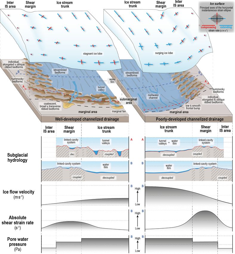
2896                   J. Vérité et al.: Formation of ribbed bedforms below shear margins and lobes of palaeo-ice streams

Figure 3. Extent of the North American Laurentide Ice Sheet during the Last Glacial Maximum with positions of known ice stream tracks
(modified from Margold et al., 2018). The areas mapped in this study in three ice streams (Amundsen Gulf, Hay River and Central Alberta
ice streams) are identified by black rectangles.

Figure 4. Evolution of pore water pressure (solid lines) measured in the trunk axis (see Fig. 5a for position) and water flow injected in the
bed through the water injector (dotted lines), for experiments 10 and 14. Points numbered 1 to 3 correspond to stages described in Sect. 4.1,
4.2 and 4.3.

The presence and migration of the water pocket induces a                 sustainability of a water film at the silicone–bed interface,
local increase in silicone flow velocity (from Vsurf = 0.2 ×             once the initial drainage event is over, contributes to main-
10−2 mm s−1 to Vsurf = 10 × 10−2 mm s−1 ) forming a 20 cm                taining a fast and durable silicone flow; the silicone stream
wide stream that propagates from the margin towards the                  switches on, and the silicone lobe keeps growing.
centre of the silicone cap. A lobe forms at the extremity of the            Landforms produced in the experiments are illustrated and
fast-flowing corridor in response to this drainage and surge             annotated in Fig. 5: these include grooves, ribbed and hum-
event. In Experiment 10, seven water pockets successively                mocky bedforms beneath the streams and marginal deltas and
form and produce an equal number of drainage events and                  pushed sediments in front of the lobes. The successive stages
lobe advances; in Experiment 14, only one drainage event                 (Figs. 6–9) are described below in relation to (i) the stream
occurs (Fig. 4). The drainage events generate marginal deltas            evolution derived from surface measurements; (ii) the for-
along the silicone margin, constituted by sand grains eroded             mation, evolution and morphometric characteristics of bed-
from the bed during the migration of the water pocket. The               forms derived from photographs in white light and DEMs;

The Cryosphere, 15, 2889–2916, 2021                                                           https://doi.org/10.5194/tc-15-2889-2021
J. Vérité et al.: Formation of ribbed bedforms below shear margins and lobes of palaeo-ice streams                                    2897

Figure 5. Illustration of bedform assemblages produced during the experiments. (a) Overall surface view of the silicone cap at the end of an
experimental run, showing the distribution of bedforms beneath a stream/lobe system characterized by well-developed channelized drainage
(Experiment 10). The white dot indicates the position of the pressure sensor where pore water pressure presented in Fig. 4 is measured.
(b) Close-up on oblique ribbed and hummocky bedforms observed at the right lateral shear margin. (c) Transverse ribbed bedforms parallel
to the lobe frontal margin and formed submarginally. Tunnel valley and associated marginal delta. (d) Transverse ribbed bedforms parallel
to the lobe frontal margin and pushed marginal sediments bulldozed by the lobe margin. (e) Network of meltwater channels extending
parallel and perpendicularly to the silicone flow (not located in panel a, because it was observed in Experiment 14, characterized by poorly
developed channelized drainage). (f) Field of grooves inscribed in the bed and oriented parallel to silicone flow with embedded sand grains
at the grooves’ downstream extremities.

and (iii) the evolution of water drainage systems derived from          ing strain rate of the strain ellipse and the shear strain rate
UV photographs and DEMs.                                                are zero in the centre of the stream trunk and in the sur-
                                                                        rounding ice cap, while they are maximal along lateral mar-
4.1.1   Stage a – initiation of ribbed bedforms beneath                 gins of the streams where the velocity gradient is the highest
        incipient shear and lobe margins                                (Figs. 7a and 9a; εcompressing = −2.5 × 10⁻⁴ s−1 ; εshear = 3
                                                                        to 5 × 10⁻⁴ s−1 ). These patterns of high shear deformation
The streams flow 10 to 20 times faster (Fig. 7a, Vsurf =                define symmetrical bands on the silicone surface and resem-
0.08 mm s−1 ; Fig. 9a, Vsurf = 0.17 mm s−1 ) than in the inter-         ble those of natural lateral shear margins (Echelmeyer et al.,
stream areas (Vsurf < 0.01 mm s−1 ), inducing velocity gradi-           1994; Raymond et al., 2001).
ents across the lateral margins of the streams. The compress-

https://doi.org/10.5194/tc-15-2889-2021                                                        The Cryosphere, 15, 2889–2916, 2021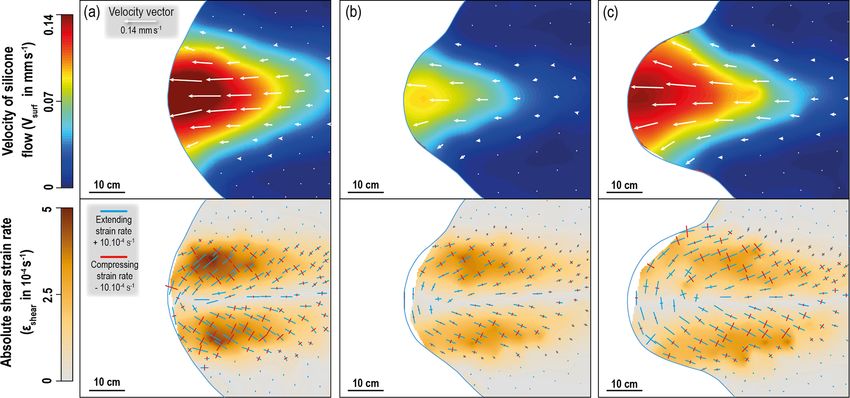
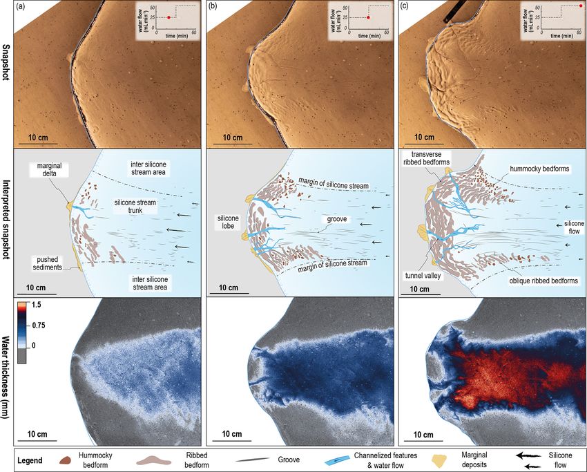
2898                   J. Vérité et al.: Formation of ribbed bedforms below shear margins and lobes of palaeo-ice streams

Figure 6. Temporal evolution (stages a, b and c) of the silicone stream and lobe system, for a typical experiment with a well-developed
channelized drainage system (Experiment 10), illustrated with snapshots representative of the three main stages of development. The upper,
intermediate and lower panels show, respectively, (i) white-light photographs of the surface of the model, (ii) interpretations of bedforms
observed on the photographs and (iii) thickness (in mm) of the water film flowing beneath the silicone cap, derived from UV photographs.

   In Experiment 10 (Fig. 7a), the stream velocity de-                  (1 mm wide, 10 to 20 mm long) highlighting the stream trunk
creases from the centre (Vsurf = 0.08 mm s−1 ) towards the              and the direction of the silicone flow (Figs. 5f). Below frontal
frontal and lateral margins (Vsurf = 0.06 mm s−1 and Vsurf =            and lateral margins, fields of periodic ridges develop trans-
0.04 mm s−1 , respectively), while the silicone–bed interfaces          versely to the ice flow, with undulating crests and an aver-
of these margins are dewatered (Fig. 7a; water thickness =              age wavelength of 8 mm (Figs. 6a and 8a). They are on av-
0). Beneath the lobe, meltwater channels, 50 to 70 mm in                erage a few millimetres thick, 7 mm wide and 30 mm long,
length and 4 to 8 mm in width, start to develop by regressive           i.e. 4 times larger in length than in width. Their shapes (un-
erosion from the margin and initiate channelization of the              dulating crest, elongation ratio) and periodic spatial organi-
water flow (Figs. 6a and 8a). Sand grains washed away by                zation (Fig. 5b and d) resemble those of ribbed bedforms ob-
bed erosion are transported within these incipient channels             served in glacial land systems. In the experiments, ribbed
towards the marginal deltas (Figs. 5c and 6a). Radial growth            bedforms initiate perpendicularly (90◦ ) to obliquely (60◦ )
and advance of the lobe over the marginal deltas form ridges            to the compressing axis of the instantaneous strain ellipse
of pushed sediments, 5 mm in width and 40 mm in length                  measured at the surface of the overlying silicone (Figs. 7a
(Figs. 5d and 6a). Below the streams (Fig. 6a and 8a), some             and 9a). Most of them form below the lobe margins perpen-
coarse sand grains are lodged in the base of the fast-flowing           dicularly to the silicone flow direction, and some scattered
silicone and carve the bed to form sets of parallel grooves             and isolated ones form below the lateral margins perpendicu-

The Cryosphere, 15, 2889–2916, 2021                                                          https://doi.org/10.5194/tc-15-2889-2021
J. Vérité et al.: Formation of ribbed bedforms below shear margins and lobes of palaeo-ice streams                                      2899

Figure 7. Temporal evolution (same stages a, b and c as in Fig. 6) of the silicone stream and lobe system, for a typical experiment with
well-developed channelized drainage (Experiment 10). The upper and lower panels show (i) the velocity field of silicone flow (mm s−1 ) and
the velocity vector maps of the silicone cap upper surface and (ii) extrapolated maps of absolute shear strain rate (s−1 ) and the orientation
of the principal axes of the instantaneous strain ellipse whose length corresponds to either the extending or the compressing strain rate (ε
in s−1 ), respectively. Maps highlight the development of the fast-flowing corridor (i.e. silicone stream) surrounded by stagnant or very slow
moving silicone (i.e. inter-stream area) and the formation of two symmetrical shear bands on both sides of the stream (i.e. the lateral shear
margins).

larly (90◦ ) to obliquely (45◦ ) to the silicone flow. Other bed-        multaneously, the stream velocity decreases by half, result-
forms with circular to ovoid shapes (mounds) form in be-                 ing in a slowdown in the advance of the frontal lobe margin
tween the ribbed bedforms. These mounds are typically less               (Fig. 6b, 28 cm in width; Fig. 7b, Vsurf = 0.04 mm s−1 ). Pro-
than 0.1 mm high, 4 mm wide and 6 mm long, with an aver-                 portionally to the slowdown intensity, the lateral shear mar-
age spacing of 10 mm. Their long axes do not show a prefer-              gins record a halving of the shear strain rate (Fig. 7b, εshear =
ential orientation (Figs. 6a and 8a). The shape and spatial or-          1.25 × 10⁻⁴ s−1 ) and strain ellipse deformation (εextending =
ganization of these mounds (Fig. 5b) resemble those of some              +2.5 × 10⁻⁴ s−1 ; εcompressing = −1.3 × 10⁻⁴ s−1 ).
hummocky bedforms in glacial land systems.                                  In contrast to the above, in Experiment 14 the pre-existing
                                                                         meltwater channels remain shallow and keep a constant
4.1.2   Stage b – channelization of the drainage system                  width but lengthen downstream in response to the migration
        below protruding lobes and evolution of ribbed                   of the lobe margin (Fig. 8b, 0.4 cm wide, 12 cm long, 0.04 cm
        bedforms                                                         deep). Meltwater channels are rectilinear with poorly de-
                                                                         veloped tributaries and lack deltas at their downstream ex-
After 30 min, channelized drainage networks develop be-                  tremities (Fig. 5e). In parallel, the silicone streamflow main-
neath the silicone lobe, draining water fed from the upstream            tains a high velocity, although a small deceleration oc-
water film towards the margin. The morphological evolution               curs (Fig. 9b, Vsurf = 0.13 mm s−1 ), sustaining lobe growth
of these networks differs between both types of experiments,             (36 cm in width). As a result, the lateral shear margins record
and we suggest it is a controlling influence on the distinc-             a small decrease in the shear strain rate (Fig. 9b, εshear =
tive evolution of stream dynamics from this point. From the              3.5 × 10⁻⁴ s−1 ) and a downstream-to-upstream decrease in
previous stage, the incipient network of meltwater channels              the strain ellipse deformation (εextending = +4.4 × 10⁻⁴ s−1 ;
in Experiment 10 evolves into tunnel valleys – character-                εcompressing = −1.9 × 10⁻⁴ s−1 ).
ized by undulating long profiles with over-deepening and ad-                Within the trunk of both experiments, the orientation and
verse slopes (Fig. 5c) – increasing in width (up to 1.2 cm),             direction of the grooves match the velocity vectors of the
length (15 cm) and depth (0.07 cm), and marginal deltas con-             silicone flow. The grooves are restricted to the fast-flowing
tinue to grow (Fig. 6b). Three individual tunnel valley sys-             corridor and display lengths of up to 5 and 8 cm for experi-
tems, two slightly sinuous valleys with some tributaries and             ments 10 and 14, respectively, and they tend to keep a con-
one anastomosed valley network, are observed (Fig. 6b). Si-

https://doi.org/10.5194/tc-15-2889-2021                                                          The Cryosphere, 15, 2889–2916, 2021
2900 J. Vérité et al.: Formation of ribbed bedforms below shear margins and lobes of palaeo-ice streams Figure 8. Temporal evolution (stages a, b and c) of the silicone stream and lobe system, for a typical experiment with poorly developed channelized drainage (Experiment 14). Same panels as in Fig. 6. stant width of approximately 0.1 cm. Grooves remain recti- 1 cm wide and 5 cm long). Their wavelength is typically 0.6 linear and parallel to the mean silicone displacement in the to 0.7 cm in Experiment 10 (Fig. 6b), while it is 1.0 to 1.5 cm upstream part of the streams but diverge and curve in the in Experiment 14 (Fig. 8b). Beneath the lobe margin of Ex- downstream area following the fan-shaped pattern of sili- periment 10, the water film ceases to exist in between the cone velocity vectors in the lobe (Figs. 6b and 8b). During tunnel valleys (Fig. 6b). These water-free areas coincide with this second stage, the ribbed bedforms keep growing but dif- the growth of pre-existing submarginal ribbed bedforms and fer below lateral shear margins (i.e. lateral ribbed bedforms) the formation of new ones parallel to the lobe margin and and frontal lobes (i.e. submarginal ribbed bedforms). Be- perpendicular to silicone velocity vectors and compressing low shear margins, new lateral ribbed bedforms with arcu- axes (Fig. 7b). They develop below the lobe from (i) the ate planforms progressively develop obliquely (45 to 60◦ ) to initial sandy bed and (ii) the recycled marginal landforms silicone velocity vectors and perpendicularly to compress- (i.e. marginal deltas and pushed sediments). The develop- ing axes of the horizontal strain ellipses. They first appear ment and the coalescence of these bedforms below the lobe near the lobe and then develop towards the upstream area tend to form a belt composed of broad, arcuate and trans- of the trunk borders. Pre-existing and newly formed lateral verse submarginal ribs (Fig. 6b; up to 1.6 cm in width, up to ribbed bedforms increase in length and width, parallel to the 8 cm in length and 1.1 cm in wavelength). In Experiment 14, extending axes and perpendicularly to the compressing axes characterized by smaller meltwater channels, only a few and of the horizontal strain ellipse, respectively (Figs. 6b and 8b; scattered submarginal ribbed bedforms – most are inherited The Cryosphere, 15, 2889–2916, 2021 https://doi.org/10.5194/tc-15-2889-2021
J. Vérité et al.: Formation of ribbed bedforms below shear margins and lobes of palaeo-ice streams                                 2901

Figure 9. Temporal evolution (same stages a, b and c as in Fig. 8) of the surface behaviour of the silicone stream and lobe system, for a
typical experiment with poorly developed channelized drainage (Experiment 14). Same panels as in Fig. 7.

from the previous stage, and a few are newly formed – of               down (Lstream = 20 cm; Vsurf = 0.02 mm s−1 ), and silicone
smaller dimensions appear (Fig. 8b; up to 0.8 cm in width              thickness along the lobe margin stabilizes at between 5 and
and up to 4 cm in length). The population of mounds re-                15 mm. In response to this slowdown, the lateral velocity
sembling hummocky bedforms keeps increasing (from 15 to                gradient decreases across the lateral stream margins, whose
40 in Experiment 10 and from 0 to 17 in Experiment 14).                width becomes constant (Lshear margin = 11 cm). In these ar-
Some mounds observed in the previous stage have evolved                eas, the deformation of the strain ellipse (εextending = +1.9 ×
into ribbed bedforms, and new mounds form with constant                10−4 s−1 ; εcompressing = −1.0×10⁻⁴ s−1 ) and the shear strain
dimensions (0.5 cm in width, 0.7 cm in length), especially in          rate (εshear = 1 × 10⁻⁴ s−1 ) stabilize at low values (Fig. 7c).
the bending zone between lobe borders and shear margins                New and pre-existing submarginal ribbed bedforms form and
(Figs. 6b and 8b).                                                     grow perpendicularly to obliquely (70◦ ) to the trunk axis and
                                                                       perpendicularly to compressing axes of the strain ellipses, re-
4.1.3   Stage c – morphological response to changes in                 spectively (Figs. 7c and 11c). Submarginal ribbed bedforms
        drainage characteristics                                       with oblique orientations correspond to bedforms that form
                                                                       and grow during the lobe spreading where the silicone veloc-
After 60 min, the two experimental runs described here show            ity vectors deviate from the trunk axis orientation. Individ-
distinctive drainage systems (well-developed vs. poorly de-            ual submarginal ribbed bedforms increase in dimensions and
veloped), silicone streams dynamics and landform develop-              tend to evolve into a roughly coalescent belt that strike per-
ment histories.                                                        pendicularly to compressing axes of the strain ellipses along
                                                                       the lobe margin (Figs. 7c and 10c; 1.4 cm in width, 4.2 cm
Well-developed channelized drainage system
                                                                       in length and 0.1 cm in height), although they still display a
(Experiment 10)
                                                                       regular wavelength, from 1.0 to 1.5 cm. New lateral ribbed
                                                                       bedforms form upstream below shear margins with orienta-
In response to the imposed increase in water discharge, tun-
                                                                       tions perpendicular to compressing axes of the strain ellipses
nel valleys increase in number (from three to four) and in
                                                                       Elevation profiles reveal they remain smaller in dimensions
dimensions (up to 1.1 cm wide, up to 16 cm long and up to
                                                                       and display lower relief than their submarginal counterparts
0.10 cm deep) and keep ensuring the drainage of the dis-
                                                                       (Fig. 10e; 2.3 cm in length, 0.7 cm in width and up to 0.07 cm
tributed water film. Tunnel valleys continue to grow down-
                                                                       in height). Pre-existing and newly formed lateral ribbed bed-
stream, tracking the advance of the lobate margin, and they
                                                                       forms are arranged in regular and oblique patterns, with a
incise the belt of submarginally produced ribbed bedforms
                                                                       mean long-axis orientation of 45◦ to the trunk axis (Fig. 11c)
formed during the previous stage, as indicated by eleva-
                                                                       and with a wavelength close to 0.7 cm (Fig. 6c). The grooves
tion profiles (Figs. 6c and 10a, d). The silicone flow ve-
                                                                       still increase in length but at a slower rate than during pre-
locity decreases along the stream axis; lobe growth slows

https://doi.org/10.5194/tc-15-2889-2021                                                      The Cryosphere, 15, 2889–2916, 2021
2902 J. Vérité et al.: Formation of ribbed bedforms below shear margins and lobes of palaeo-ice streams Figure 10. DEMs of the bed surface beneath the lobes of the silicone streams at the final stage of Experiment 10 (blue) and Experiment 14 (brown). Ten elevation profiles (a–e) within the lobes are drawn to compare the morphological imprint beneath the two types of stream. The Cryosphere, 15, 2889–2916, 2021 https://doi.org/10.5194/tc-15-2889-2021
J. Vérité et al.: Formation of ribbed bedforms below shear margins and lobes of palaeo-ice streams                                      2903

Figure 11. Morphometric properties of bedforms produced beneath each type of stream at the final stage of experiments 10 (b, d) and
14 (a, c) plotted according to the distance from the silicone stream central axis. (a, b) Relationship between groove length and silicone flow
velocity (mm s−1 ). (c, d) Variation in orientation relative to silicone stream axis of each population of bedforms (lateral ribs, submarginal
ribs, hummocky) compared to the silicone flow velocity and the shear band position (grey columns; defined as εshear > 0.5 × 10⁻⁴ s−1 ).

vious stages, although remaining subparallel (0–10◦ ) to the             with a strain ellipse rotation increasing downstream (α is up
silicone flow direction (Fig. 11c). The position and length of           to 18◦ ; LR = 25 %) and a maximal value of the shear strain
the grooves correlate with the time-averaged velocity profile            rate localized along stream borders (εshear = 3 × 10⁻⁴ s−1 ).
measured across the silicone stream (Fig. 11a). Hummocky                 As the lobe advances, the stream thins and the silicone col-
bedforms occur either sparsely between lateral ribbed bed-               umn is 20 mm thick along shear margins. The shear margins
forms or more densely in lobe corners. Their average length              widen downstream, reaching a maximum width at the sil-
is 0.6 cm, and their average width is 0.4 cm (Fig. 6c).                  icone cap margin within the lobe corners (Lshear band is up
                                                                         to 20 cm). Simultaneously with the downstream migration of
Poorly developed channelized drainage system                             the water film, the submarginal ribbed bedforms are eroded
(Experiment 14)                                                          and evolve into a single shallow and smooth submarginal re-
                                                                         lief slightly higher than the trunk (Fig. 10c). Located beneath
In response to the imposed increase in water discharge, the              the shear margins, the lateral ribbed bedforms keep increas-
sparse, shallow and narrow meltwater channels characterized              ing in number (from 26 to 42) and in dimensions (Figs. 8c
by smoothly undulating long profiles (Fig. 10a and d; n = 9,             and 10e; 3.6 cm in length, 1.1 cm in width and up to 0.09 cm
up to 0.5 cm in width and up to 0.05 cm in depth) are not                in height). New lateral ribbed bedforms form almost perpen-
able to evacuate all the water transmitted to the bed. Thus,             dicularly (70 to 90◦ ) to compressing axes of the strain el-
the distributed water film, hitherto constrained to the upper-           lipses, while some pre-existing ones become progressively
most part of the stream, spreads down to the lobe (Fig. 8c).             rotated because of the lobe spreading, resulting in the shift
The stream velocity increases, and the lobe undergoes a surge            and rotation of the downstream part of the lateral shear mar-
(Fig. 9c; Vsurf = 0.15 mm s−1 ). The high velocity gradient              gins. Lateral ribbed bedforms are characterized by subnormal
between the stream and the inter-stream area maintains a high            to oblique long axes, deviating by 80 to 40◦ from the main
rate of deformation of the silicone along the shear margins,             trunk axis and with a mean orientation of 50◦ (Fig. 11d).

https://doi.org/10.5194/tc-15-2889-2021                                                          The Cryosphere, 15, 2889–2916, 2021
2904 J. Vérité et al.: Formation of ribbed bedforms below shear margins and lobes of palaeo-ice streams
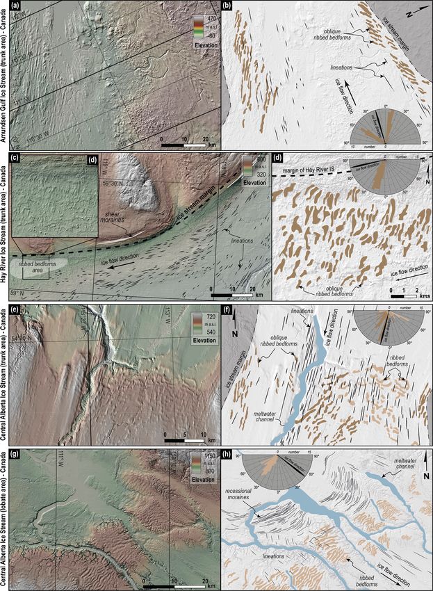
They are spaced with a wavelength of between 1.5 and 1.9 cm In the upstream portion of the Central Alberta Ice Stream
(Fig. 10e) and develop on both sides of a flat and grooved (CAIS), oblique and transverse ribbed bedforms (n = 71) are
trunk (Fig. 10c). The corridors of lateral oblique ribbed bed- also recognized. Similarly to for the AGIS and HRIS, the
forms thus constitute two bands of topographic highs below ice stream trunk is characterized by topographic borders, a
the shear margins (Fig. 10b). smoother bed than the surrounding landscape, a meltwater
The grooves are more elongated near the trunk axis where channel and a swarm of lineations. The ribbed bedforms lo-
the highest flow velocities and the greatest cumulative dis- cated to the east of the meltwater channel are superimposed
placement are recorded (Fig. 11b). Following the radial by lineations, while the oblique ribbed bedforms along the
spreading of the silicone velocity vectors towards the lobate ice stream margins are apparently not overprinted by other
margin, the groove orientations curve and form a fan-shaped structures. The ribbed bedforms display orientations rang-
swarm (Fig. 8c). Groove orientations mostly remain subpar- ing from 15 to 25◦ to streamlined bedforms for the slightly
allel to the local silicone flow, with a maximum deviation of oblique set, while the transverse set displays orientations de-
15◦ from the silicone flow direction (Fig. 11d). Sparse hum- viating by 85◦ . They are 2660 m in length and 690 m in width
mocky bedforms (width is 0.6 cm; length is 1.0 cm) occasion- – thus displaying a mean elongation ratio of 3.8 – and have
ally occur within the corridors of lateral ribbed bedforms. a mean wavelength of 685 m (Fig. 12e and f). The oblique
ribbed bedforms are characterized by less arcuate and more
elongated shapes than the transverse ones. Downstream and
4.2 Palaeoglaciology – ribbed bedforms beneath ice
further south in the CAIS is a widespread belt of transverse
stream margins
ribbed bedforms (n = 92; mean orientation is 95◦ ) over-
printed with perpendicular lineations and cross-cut by large
Palaeo-ice stream trunks of the Laurentide Ice Sheet – both meltwater channels (width is 6 to 3.4 km). This belt presents
with marine (Fig. 12a and b) and terrestrial (Fig. 12c–h) mar- a regular pattern of arcuate and coalescent ribbed bedforms
gins – are characterized by dense swarms of streamlined bed- (wavelength is 600 to 1200 m), paralleling a curved belt of
forms (e.g. mega-scale glacial lineations, drumlins), evidenc- fine, linear and almost continuous ridges – similar to reces-
ing former ice flow directions. Several ice streams have been sional moraines – depicted further north. The mean length
identified, mapped and described by others and were com- (4350 m), width (1350 m) and elongation ratio (l/w = 3.0)
piled by Margold et al. (2015). These streams were recog- of the ribbed bedforms show that these ridges are longer
nized through sharp transitions in streamlined bedform zona- and wider but less elongated than the oblique and transverse
tion, topographic borders, shear moraines and marginal bed- ridges upstream (Fig. 12g and h).
forms. In total, we mapped 303 ribbed bedforms in four dis-
tinct areas on three palaeo-ice stream beds.
In the eastern branch of the marine-based Amundsen Gulf 5 Discussion
Ice Stream (AGIS), the trunk is characterized by streamlined
bedforms delimited by two topographic borders. Two fields 5.1 Morphometric comparisons between experimental
of ribbed bedforms (n = 62) elongated obliquely (mean ori- and natural ribbed bedforms
entation is 25 to 45◦ ) to the streamlined bedforms occur
along the lateral margins. The internal part (i.e. close to the Our experiments and observations suggest that ribbed bed-
trunk axis) of those two fields is partially overprinted by the forms can develop in lateral corridors and submarginal belts
streamlined bedforms observed along the trunk. The ribbed displaying transverse or longitudinal ice velocity gradients,
bedforms display elongated and arcuate shapes (l/w = 4.2; like shear margins and lobes of ice streams, respectively.
mean length is 4780 m; mean width is 1110 m) and a mean They occur along the borders of swarms of elongated struc-
wavelength of 1450 m (Fig. 12a and b). tures (Figs. 6, 8 and 12; i.e. lineations in nature and grooves
In the northern portion of the Hay River Ice Stream in the experiments) that reveal fast-flowing trunks (Stokes
(HRIS), broad arcuate to rectangular ribbed bedforms (n = and Clark, 2001; Clark and Stokes, 2003). Beneath the shear
78) strike obliquely to the streamlined bedforms of the trunk. margins of the experimental ice streams, the lateral ribbed
The ridges are clustered in an elongated corridor located be- bedforms form perpendicularly to the compressing axis of
tween the northern shear margin and the swarm of stream- the strain ellipse. Their mean long-axis orientation strikes at
lined bedforms. The shear margin is marked by topographic ∼ 45◦ to the trunk axis and to the boundaries of lateral shear
borders, a sharp transition between a rough inter-ice-stream margins (Fig. 10c and d), and they tend to gather in corridors
terrain and a smooth trunk covered by lineations, and lin- elongated parallel to the flow direction. In the experiments,
ear ridges similar to shear moraines. The ribbed bedforms their elongation ratio of 3.3 (mean length is 3 cm; mean width
exhibit a mean orientation of 55◦ to streamlined bedforms is 0.9 cm) lies in between those of natural intermediate-sized
and a mean wavelength of 460 m. Those ridges are shorter ribbed bedforms considered the topographic expression of
(1040 m in length and 360 m in width) and slightly less elon- traction ribs and those of mega-scale transverse ridges, fit-
gated (l/w = 2.9) than those of the AGIS (Fig. 12c and d). ting a moderately elongated type of ribbed bedform. The
The Cryosphere, 15, 2889–2916, 2021 https://doi.org/10.5194/tc-15-2889-2021You can also read