Fronius Symo 3 - 8,2 kW - Fronius International
←
→
Page content transcription
If your browser does not render page correctly, please read the page content below
/ Perfect Charging / Perfect Welding / Solar Energy

                                                                                Installations instructions
Fronius Symo 3 - 8,2 kW                                                   EN

                                                                                Grid-connected inverter

                 42,0426,0172,EN 019-06112019

Fronius prints on elemental chlorine free paper (ECF) sourced from certified sustainable forests (FSC).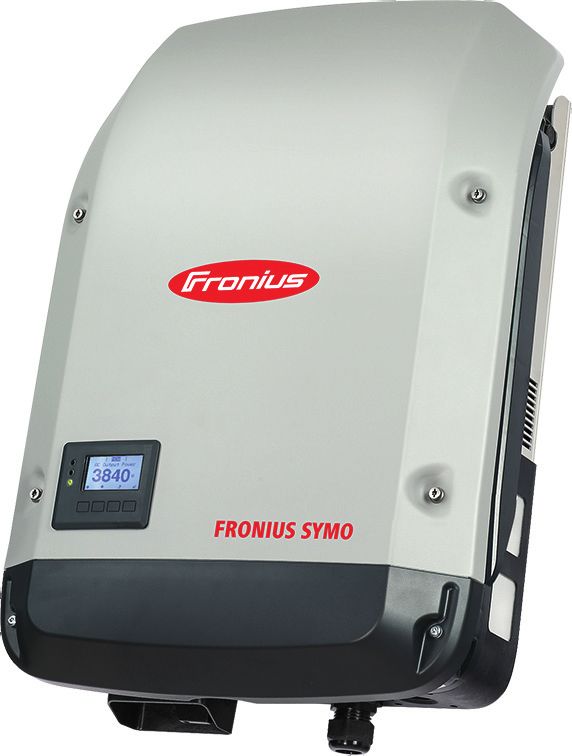
2
Contents
EN
Installation location and position ................................................................................................................ 5
Explanation of safety notices ................................................................................................................ 5
Safety.................................................................................................................................................... 5
Proper use/intended purpose................................................................................................................ 6
Inverter installation location .................................................................................................................. 7
Explanation of symbols - installation position ....................................................................................... 8
General comments regarding inverter installation location ................................................................... 9
Attaching the Mounting Bracket ................................................................................................................. 10
Safety.................................................................................................................................................... 10
Selecting wall plugs and screws ........................................................................................................... 10
Recommended screws ......................................................................................................................... 10
Opening the inverter ............................................................................................................................. 10
Fitting the mounting bracket to a wall ................................................................................................... 11
Fitting the mounting bracket to a mast or support................................................................................. 12
Fitting the mounting bracket to metal supports ..................................................................................... 12
Do not warp or deform the mounting bracket........................................................................................ 13
Connecting the inverter to the public grid (AC side) .................................................................................. 14
Safety.................................................................................................................................................... 14
Monitoring the grid ................................................................................................................................ 14
Type of AC cable .................................................................................................................................. 14
Preparing the aluminium cables for connection .................................................................................... 14
AC terminals ......................................................................................................................................... 15
Cross section of the AC cable............................................................................................................... 15
Connecting the inverter to the public grid (AC) ..................................................................................... 16
Maximum fuse rating on alternating current side .................................................................................. 16
Notes regarding inverters with single and multiple MPP trackers .............................................................. 18
Inverter with single MPP tracker ........................................................................................................... 18
Inverter with multiple MPP trackers ...................................................................................................... 18
Connecting solar module strings to the inverter......................................................................................... 20
Safety.................................................................................................................................................... 20
General comments regarding solar modules ........................................................................................ 21
DC terminals ......................................................................................................................................... 21
Connecting aluminium cables ............................................................................................................... 21
Solar module strings - checking the polarity and voltage...................................................................... 22
Connecting solar module strings to the inverter (DC) ........................................................................... 22
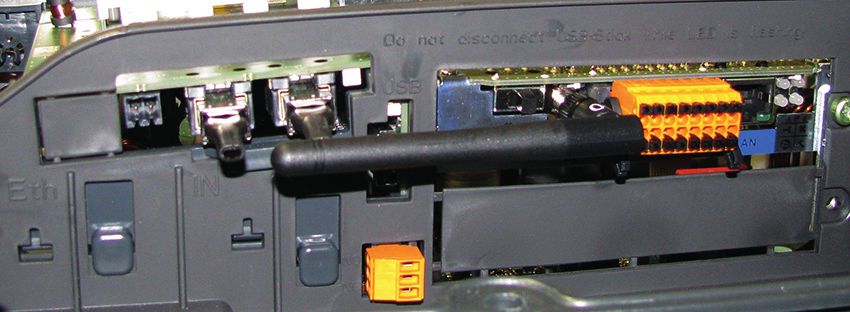
Data communication .................................................................................................................................. 26
Routing data communication cables ..................................................................................................... 26
Installing the Datamanager in the inverter ............................................................................................ 26
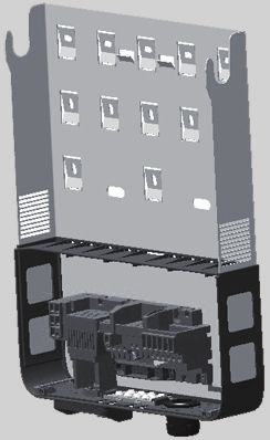
Attaching the inverter to the mounting bracket .......................................................................................... 29
Attaching the inverter to the mounting bracket ..................................................................................... 29
Starting for the first time ............................................................................................................................. 31
Starting the inverter for the first time..................................................................................................... 31
Notes regarding software updates ............................................................................................................. 33
Notes regarding software updates ........................................................................................................ 33
USB Stick as a Data Logger and for Updating Inverter Software .............................................................. 34
USB flash drive as a datalogger ........................................................................................................... 34
Data on the USB stick........................................................................................................................... 34
Data volume and storage capacity........................................................................................................ 35
Buffer memory ...................................................................................................................................... 36
Suitable USB flash drives ..................................................................................................................... 36
USB stick for updating the inverter software......................................................................................... 37
Remove USB stick ................................................................................................................................ 37
Notes regarding maintenance.................................................................................................................... 38
Maintenance ......................................................................................................................................... 38
Cleaning................................................................................................................................................ 38
Australian cable protection hoses .............................................................................................................. 39
Seal cable protection hoses tightly ....................................................................................................... 39
Seal Conduits........................................................................................................................................ 39
Serial Number Sticker for Customer Use ................................................................................................... 40
Serial number sticker for customer use ................................................................................................ 40
3
4

Installation location and position

                                                                                                          EN
Explanation of
safety notices           DANGER!
                 Indicates immediate danger.
                 ► If not avoided, death or serious injury will result.

                         WARNING!
                 Indicates a potentially hazardous situation.
                 ► If not avoided, death or serious injury may result.

                         CAUTION!
                 Indicates a situation where damage or injury could occur.
                 ► If not avoided, minor injury and/or damage to property may result.

                  NOTE!
                 Indicates a risk of flawed results and possible damage to the equipment.

Safety
                         WARNING!
                 Danger due to incorrect operation and incorrectly performed work.
                 This can result in serious injury and damage to property.
                 ► Only qualified staff are authorised to commission your inverter and only within the
                     scope of the respective technical regulations.
                 ► Read the Installation and Operating Instructions before installing and commissioning
                     the equipment.

                         WARNING!
                 Danger due to work that has been carried out incorrectly.
                 This may result in serious injury and damage to property.
                 ► A surge protective device must only ever be installed and connected by a qualified
                     electrical engineer.
                 ► Follow the safety rules.
                 ► Ensure that both the AC side and the DC side of the inverter are de-energised before
                     carrying out any installation and connection work.

                 Fire prevention

                                                                                                      5
CAUTION!
                 Danger due to poor or unprofessional installation.
                 This may result in damage to inverters and other live
                 photovoltaic system components.
                 Poor or unprofessional installation can cause overheat-
                 ing of cables and terminal connections and result in
                 arcs. These can cause heat damage, which in turn may
                 lead to fires.

                 Observe the following when connecting AC and DC ca-          3
                 bles:
                 ► Tighten all terminals to the torque specified in the    2
                     Operating Instructions
                                                                                           1
                 ► Tighten all grounding terminals (PE / GND), includ-        2.5 Nm
                     ing free ones, to the torque specified in the Operat-
                     ing Instructions
                 ► Do not overload cables
                 ► Check cables for damage and verify that they are laid correctly
                 ► Take note of the safety instructions, Operating Instructions and any local connection
                     regulations

                 ► Using fastening screws, always screw the inverter firmly to the mounting bracket to the
                   torque specified in the Operating Instructions.
                 ► Ensure that the fastening screws are tight before starting the inverter!

                 Note! Fronius will not accept any costs associated with production downtimes, installer
                 costs, etc., that may arise as the result of a detected arc and its consequences. Fronius
                 accepts no liability for fires that can occur despite the presence of the integrated arc detec-
                 tion/extinguishing system (e.g. fires caused by a parallel arc).

                 Note! After an arc has been detected, the entire photovoltaic system must be checked for
                 possible damage before resetting the inverter.

                 Observe the manufacturer's connection, Installation and Operating Instructions at all times.
                 To reduce the hazard potential to a minimum, perform all installation and connection work
                 carefully according to the instructions and regulations.
                 Refer to the device Installation Instructions for the tightening torques to be used at the rel-
                 evant terminal connections.

Proper use/in-   The inverter is intended exclusively to convert direct current from solar modules into alter-
tended purpose   nating current and to feed this into the public grid.
                 Utilisation not in accordance with the intended purpose comprises:
                 -     Any use above and beyond this purpose
                 -     Making any modifications to the inverter that have not been expressly approved by
                       Fronius
                 -     the installation of components that are not distributed or expressly approved by Froni-
                       us.

                 Fronius shall not be liable for any damage resulting from such action.
                 No warranty claims will be entertained.

                 Proper use also includes:
                 -   Carefully reading and obeying all the instructions and all the safety and danger notices
                     in the Operating Instructions and Installation Instructions
                 -   Performing all stipulated maintenance work
                 -   Installation as specified in the Installation Instructions

6
When designing the photovoltaic system, ensure that all components are operated within
                     their permitted operating ranges at all times.

                                                                                                                         EN
                     Observe all the measures recommended by the solar module manufacturer to ensure that
                     the solar module retains its properties in the long term.

                     Obey the regulations of the power supply company regarding connection methods and en-
                     ergy fed into the grid.

Inverter installa-
tion location
                                     The inverter is suitable for installation indoors.

                                     The inverter is suitable for installation outdoors.

                                     Its IP 65 degree of protection means that the inverter is resistant to water
                     IP 65
                                     jets from any direction and can also be used in damp environments.

                                     In order to minimise the heating up of the inverter, do not expose it to di-
                                     rect insolation. Install the inverter in a protected location, e.g. in the vicin-
                                     ity of the solar modules or beneath the eaves.

                      2500 m
                       UDCmax =      UDCmax at an altitude of:
                       900 V
                      2000 m         0 to 2000 m = 1000 V
                      2000 m
                       UDCmax =      2000 to 2500 m = 900 V
                       1000 V
                                     2500 to 3000 m = 815 V
                                     3000 to 3400 m = 750 V
                       > 3400 m
                       3400 m
                        UDCmax =
                        750 V
                       3000 m
                                     IMPORTANT! The inverter must not be installed or used at altitudes
                       3000 m
                        UDCmax =
                                     above 3400 m.
                        815 V
                       2500 m

                        NH3
                                     Do not install the inverter in:
                                     -   areas where ammonia, corrosive vapours, acids or salts are present
                                         (e.g. fertiliser stores, ventilation openings from cattle sheds, chemi-
                                         cal plants, tanneries, etc.)

                                     As the inverter generates low levels of noise under certain operating con-
                                     ditions, it should not be installed close to living areas.

                                     Do not install the inverter in:
                                     -   places where there is an increased risk of damage from farm ani-
                                         mals (horses, cattle, sheep, pigs, etc.)
                                     -   stables or adjoining areas
                                     -   storage areas for hay, straw, chaff, animal feed, fertilisers, etc.

                                                                                                                     7
All inverters are designed to be dust-tight. However, in areas with a
heavy build-up of dust, the thermal efficiency may still be impaired by
dust forming on the cooling surfaces. Regular cleaning is necessary in
such situations. It is therefore not recommended to mount the device in
rooms or areas in which a heavy build-up of dust is expected.
Do not install the inverter in:
- greenhouses
- storage or processing areas for fruit, vegetables or winegrowing
products
- places used to prepare grain, green fodder or animal feeds
Explanation of
symbols - instal-
lation position
The inverter is designed to be installed vertically on a vertical wall or pil-
lar.
The inverter is suitable for horizontal installation.
The inverter is suitable for installation on a sloping surface.
Do not install the inverter on a sloping surface with its connection sockets
facing upwards.
Do not install the inverter at an angle on a vertical wall or pillar.
Do not install the inverter horizontally on a vertical wall or pillar.
8EN
Do not install the inverter on a vertical wall or pillar with its connection
sockets facing upwards.
Do not install the inverter such that it overhangs with its connection sock-
ets facing upwards.
Do not install the inverter such that it overhangs with its connection sock-
ets facing downwards.
Do not install the inverter on the ceiling.
General com- The following criteria should be taken into account when choosing a location for the invert-
ments regarding er:
inverter installa-
tion location
Install only on a solid, non-flammable surface
Max. ambient temperatures:
150 mm -25 °C / +60 °C
Relative humidity:
0 - 100%
The airflow within the inverter is from the
left to the top (cold air taken in from the
100 mm
left, hot air dissipated out of the top).
100 mm The exhaust air can reach a temperature
-25 °C
of 70 °C.
-+
0 - 100 60 °C
%
If the inverter is installed in a switch cabinet or a similar sealed area, then forced-air ven-
tilation must be provided to ensure adequate heat dissipation.
If the inverter is to be installed on the outer wall of a cattle shed, maintain a minimum all-
round clearance of 2 m between the inverter and all ventilation and other openings in the
building.
The installation location must not be exposed to ammonia, corrosive vapours, salts or ac-
ids.
9Attaching the Mounting Bracket
Safety
WARNING!
Danger due to residual voltage in capacitors.
This may result in an electric shock.
► Wait for the capacitors to discharge. The discharge time is five minutes.
CAUTION!
Danger due to dirt or water on the terminals and contacts of the inverter's connec-
tion area.
This may result in damage to the inverter.
► When drilling, ensure that terminals and contacts in the connection area do not be-
come dirty or wet.
► The mounting bracket without a power stage set does not conform to the protection
class of the inverter as a whole, and therefore must not be installed without a power
stage set.
► The mounting bracket should be protected from dirt and moisture during installation.
Note! Degree of protection IP 65 is only applicable if
- the inverter is placed in the mounting bracket and permanently attached using
screws
- the cover for the data communication area is permanently attached to the inverter with
screws.
Degree of protection IP 20 applies to the mounting bracket with no inverter and the venting
duct.
Selecting wall Important! Different fixings may be required to fit the mounting bracket depending on the
plugs and screws type of underlying surface. Fixings are therefore not included in the scope of supply of the
inverter. The installer is responsible for selecting the right type of fixing.
Recommended To install the inverter, the manufacturer recommends the use of steel or aluminium screws
screws with a diameter of 6 - 8 mm.
Opening the in-
verter WARNING!
Danger from inadequate ground conductor connection.
This can result in serious injury and damage to property.
► The housing screws provide a suitable ground conductor connection for grounding the
housing and must NOT be replaced by any other screws that do not provide a reliable
ground conductor connection.
101 2
1 2
EN
3 4
3 4
Fitting the mount-
1 2
1 2
ing bracket to a
wall
Tip: Install the inverter so that its display is at eye level
113
3 Note! When mounting the mounting bra-
cket on the wall, ensure that the mounting
bracket does not become warped or defor-
med.
Fitting the mount- When installing the inverter on a mast or
ing bracket to a support, Fronius recommends the "Pole
mast or support Clamp" kit from Rittal GmbH (order no. SZ
2584.000).
This kit enables the inverter to be installed
on round or rectangular masts with the fol-
lowing diameters: from 40 to 190 mm
(round mast), from 50 to 150 mm (rectan-
gular mast)
Fitting the mount- The mounting bracket must be securely screwed to at least four points.
ing bracket to
1
1
metal supports
12Do not warp or Note! When fitting the mounting bracket to the wall, ensure that the mounting bracket does
EN
deform the not become warped or deformed.
mounting bracket
13Connecting the inverter to the public grid (AC side)
Safety
WARNING!
Danger due to incorrect operation and incorrectly performed work.
This may result in serious injury and damage to property.
► Only qualified staff are authorised to commission your inverter and only within the
scope of the respective technical regulations.
► Read the Installation and Operating Instructions before installing and commissioning
the equipment.
WARNING!
Danger due to grid voltage and DC voltage from solar modules that are exposed to
light.
This may result in an electric shock.
► Ensure that both the AC side and the DC side of the inverter are de-energised before
carrying out any connection work.
► Only an authorised electrical engineer is permitted to connect this equipment to the
public grid.
CAUTION!
Danger due to incorrectly tightened terminals.
This may result in heat damage to the inverter, which may lead to fire.
► When connecting AC and DC cables, ensure that all the terminals are tightened to the
specified torque.
Monitoring the To provide the best possible grid monitoring, the resistance in the leads to the AC-side ter-
grid minals should be as low as possible.
Type of AC cable The following types of AC cable can be connected to the AC terminals of the inverter:
Cu / Al Cu
- copper or aluminium: round, single wire
- Copper: round, finely stranded up to conductor category 4
Preparing the alu- The AC-side terminals are suitable for connecting single-wire, round aluminium cables. Be-
minium cables for cause of the formation of a non-conductive oxide layer due to the reaction of aluminium
connection with air, the following points must be considered when connecting aluminium cables:
- the reduced rated currents for aluminium cables
- the connection conditions listed below
Always follow the cable manufacturer instructions when using aluminium cables.
When designing cable cross-sections, take local regulations into account.
Connection conditions:
141 Carefully clean the oxide layer from the bare end of the cable by scraping it, e.g. with
a knife
EN
IMPORTANT! Do not use brushes, files or emery paper, as the aluminium particles get
trapped and can be transferred to other conductors.
2 Once the oxide layer is removed, rub the end of the cable with a neutral grease, such
as non-acidic and non-alkaline Vaseline
3 Immediately connect the cable end to the terminal
IMPORTANT!Repeat the procedure if the cable has been disconnected and is to be re-
connected.
AC terminals PE Ground conductor / grounding
L1-L3 Phase conductor
N Neutral conductor
Max. cross-section of each conductor cab-
le:
16 mm²
Min. cross-section of each conductor cable:
in accordance with the fuse rating on the
AC side, but at least 2.5 mm²
The AC cables can be connected to the AC
terminals without ferrules.
IMPORTANT! When using ferrules for AC cables with a cross-section of 16 mm², the fer-
rules must be crimped with a right-angled cross-section.
The use of ferrules with insulating collars is only permitted up to a max. cable cross-section
of 10 mm².
Cross section of For a standard M32 metric screw joint with a reducer:
the AC cable Cable diameter from 7-15 mm
When using an M32 metric screw joint (reducer removed):
cable diameter from 11-21 mm
(with a cable diameter of less than 11 mm, the strain-relief force is reduced from 100 N to
a maximum of 80 N)
With cable diameters greater than 21 mm, the M32 screw joint must be replaced by an M32
screw joint with a larger clamping area – item number: 42,0407,0780 – strain-relief device
M32 x 1.5 KB 18–25.
15Connecting the
1 2
1 2
inverter to the
public grid (AC) 1
OFF
Cu / Al Cu
max. Class 4
> 250 mm
PE
AC
15 mm PE ~
> 200 mm
3
3 Note! Observe the torque values marked
on the side underneath the terminals.
Torque (Nm /
lbf.in.) → see
printing near
wire terminal
Maximum fuse
rating on alternat-
ing current side AC ~
max. C 25 A
Inverter Phases AC power Maximum Recommend-
fuse rating ed fuse rating
Fronius Symo 3.0-3-S / -M 3 3000 W C 25 A C 10 A
Fronius Symo 3.7-3-S / -M 3 3700 W C 25 A C 13 A
Fronius Symo 4.5-3-S / -M 3 4500 W C 25 A C 16 A
Fronius Symo 5.0-3-M 3 5000 W C 25 A C 16 A
Fronius Symo 6.0-3-M 3 6000 W C 25 A C 16 A
Fronius Symo 7.0-3-M 3 7000 W C 25 A C 20 A
Fronius Symo 8.2-3-M 3 8200 W C 25 A C 25 A
16IΔN ≥ 100 mA
EN
? RCD
§ YES
National Standards
Type A
Note!
Local regulations, the electricity retailer or other factors may require a residual-current pro-
tective device in the AC connection lead.
A type A residual-current circuit breaker with a trip current of at least 100 mA is generally
sufficient in this case. In particular cases, and depending on local factors, however, the
type A residual-current circuit breaker may trip at the wrong time. For this reason, Fronius
recommends that a residual-current circuit breaker that is suitable for frequency converters
should be used.
17Notes regarding inverters with single and multiple
MPP trackers
Inverter with sin- Fronius Symo 3.0-3-S / 3.7-3-S / 4.5-3-S
gle MPP tracker
In the case of these inverters, there are 3
Fronius Symo terminals available for each DC+ and DC-.
3.0-3-S / 3.7-3-S / 4.5-3-S The terminals are internally connected and
are not fused. This means that a maximum
PV 1 of three strings can be connected directly to
the inverter in parallel.
In this case, the solar modules must be able
to carry at least the single reverse current
(for 2 strings) or twice the reverse current
DC-1
(for 3 strings) (see data safety sheet for so-
DC+1 DC+ DC- lar module).
1 2 3 1 2 3
Where there are more than three strings, an
external combiner box with string fuses
must be used. In this case, the strings must
contain the same number of solar modules.
Connecting one solar module field to an inverter with a
single MPP tracker
Inverter with mul- Fronius Symo 3.0-3-M - 8.2-3-M
tiple MPP track-
ers In the case of inverters with multiple MPP
Fronius Symo 3.0-3-M - 8.2-3-M
trackers, there are two independent DC in-
PV 1
PV 2 puts (MPP trackers) available. These can
be connected to an unequal number of so-
lar modules.
There are two terminals for DC+ available
per MPP tracker. In total there are four ter-
minals for DC-.
DC-1 DC-2
DC+1 DC+2 Connecting two to four strings in multiple
DC+1 DC+2 DC- MPP tracker mode:
1 1 2 2 1234 divide the strings between the two MPP tra-
cker inputs (DC+1/DC+2). The DC- termi-
nals can be used however you wish, as
they are internally connected.
When starting for the first time, set MPP
Connecting two solar module fields to an inverter with TRACKER 2 to "ON" (this can also be done
multiple MPP trackers later in the Basic menu)
18Fronius Symo 3.0-3-M - 8.2-3-M Single MPP tracker mode on an inverter
with multiple MPP trackers:
PV 1
EN
PV 2
If the strings are connected using a string
combiner box and only one bus is used for
String current > 32 A
connect
connection to the inverter, the connection
DC+1 and DC+2 * DC+1 (pin 2) and DC+2 (pin 1) must be
jumpered.
DC+1 DC+2 DC-
1 1 2 2 1234 The wire diameter of the DC connection
lead and the jumpering must be the same.
DC-1 DC+1 Jumpering of the DC terminal is not neces-
* sary, as these terminals are jumpered inter-
nally.
* D1 D1
= When starting for the first time, set MPP
TRACKER 2 to "OFF" (this can also be
Connecting multiple interconnected solar module done later in the Basic menu)
fields to an inverter with multiple MPP trackers using
one lead If the inverter with multiple MPP trackers is
operated in single MPP tracker mode, the
currents from the connected DC leads are
divided evenly across both inputs.
19Connecting solar module strings to the inverter
Safety
WARNING!
Danger due to incorrect operation and incorrectly performed work.
This can result in serious injury and damage to property.
► Only qualified staff are authorised to commission your inverter and only within the
scope of the respective technical regulations.
► Read the Installation and Operating Instructions before installing and commissioning
the equipment.
WARNING!
Danger due to grid voltage and DC voltage from solar modules that are exposed to
light.
This may result in an electric shock.
► Ensure that both the AC side and the DC side of the inverter are de-energised before
carrying out any connection work.
► Only an authorised electrical engineer is permitted to connect this equipment to the
public grid.
WARNING!
Danger due to grid voltage and DC voltage from solar modules.
This may result in an electric shock.
► The DC main switch is only to be used to de-energise the power stage set. The con-
nection area is still live when the DC main switch is switched off.
► Ensure that the power stage set and connection area are disconnected from one an-
other before carrying out any maintenance or service tasks.
► The power stage set, which is enclosed in a separate housing, must only be discon-
nected from the connection area when in a de-energized state.
► Maintenance and servicing in the power stage set of the inverter must only be carried
out by Fronius-trained service technicians.
CAUTION!
Danger due to incorrectly tightened terminals.
This may result in heat damage to the inverter, which may lead to fire.
► When connecting AC and DC cables, ensure that all the terminals are tightened to the
specified torque.
CAUTION!
Danger due to overloading.
This may result in damage to the inverter.
► Fronius Symo: The maximum amperage when connecting to a single DC terminal is 33
A.
► Fronius Eco: The maximum amperage when connecting to a single DC terminal is 15
A.
► Connect the DC+ and DC- cables to the DC+ and DC- terminals on the inverter, taking
care to ensure that the polarity is correct.
► Observe the maximum DC input voltage.
20Note! The solar modules connected to the inverter must comply with the IEC 61730 Class
A standard.
EN
Note! When photovoltaic modules are exposed to light, they supply current to the inverter.
General com- To enable suitable solar modules to be chosen and to use the inverter as efficiently as pos-
ments regarding sible, it is important to bear the following points in mind:
solar modules - If insolation is constant and the temperature is falling, the open circuit voltage of the
solar modules will increase. The open circuit voltage must not exceed the maximum
permissible system voltage. If the open circuit voltage exceeds the specified values,
the inverter will be destroyed and no warranty claims will be entertained.
- The temperature coefficients on the solar modules data sheet must be observed.
- More exact values for dimensioning the solar modules can be provided by suitable cal-
culation programs, like the Fronius Solar.configurator (which can be downloaded from
http://www.fronius.com).
Note! Before connecting up the solar modules, check that the voltage for the solar modules
specified by the manufacturer corresponds to the actual measured voltage.
DC terminals Cable cross sections of each DC cable:
D+ / D- Strings
minimum 2.5 mm² - maximum 16 mm²
min. 2,5 mm² - max. 16 mm²
The DC cables can be connected to the DC
terminals without ferrules.
DC= (+) DC= (-)
D1 D1 Note! To ensure effective strain relief of the
solar module strings, only use cables with
identical cross-sections.
D1
D1
D2 D3
IMPORTANT! When using ferrules for DC cables with a cross-section of 16 mm², the fer-
rules must be crimped with a right-angled cross-section.
The use of ferrules with insulating collars is only permitted up to a max. cable cross-section
of 10 mm².
Connecting alu- The DC-side terminals are suitable for connecting single-wire, round aluminium cables.
minium cables Because of the formation of a non-conductive oxide layer due to the reaction of aluminium
with air, the following points must be considered when connecting aluminium cables:
- the reduced rated currents for aluminium cables
- the connection conditions listed below
Note! Always follow the cable manufacturer instructions when using aluminium cables.
21Note! When designing cable cross-sections, take local regulations into account.
Connection conditions:
1 Carefully clean the oxide layer from the bare end of the cable by scraping it, e.g. with
a knife
IMPORTANT! Do not use brushes, files or emery paper, as the aluminium particles get
trapped and can be transferred to other conductors.
2 Once the oxide layer is removed, rub the end of the cable with a neutral grease, such
as non-acidic and non-alkaline Vaseline
3 Immediately connect the cable end to the terminal
IMPORTANT! Repeat the procedure if the cable has been disconnected and is to be re-
connected.
Solar module
strings - checking 900V
the polarity and 815V CAUTION!
750V
voltage Danger due to incorrect polarity and vol-
tage.
This may result in damage to the inverter.
► Check the polarity and voltage of the
solar module strings before making the
connection. The voltage must not
exceed the following values:
► When installed between 0 and 2000 m
above sea level: 1000 V
► When installed between 2001 and 2500
m above sea level: 900 V
► When installed between 2501 and 3000
m above sea level: 815 V
► When installed between 3001 and 3400
m above sea level: 750 V
Connecting solar Note! Only break out as many target break points as there are cables.
module strings to
the inverter (DC)
1 2
1 2
223 4
3 4
EN
D > 6 mm
15 mm
70 mm
D1 D1
D2 D1
D1
D3
5 6
5 6
7
7
3.0-3-S
3.7-3-S
PV PV PV
4.5-3-S
3.0-3-M
3.7-3-M
4.5-3-M
5.0-3-M PV1 PV1 PV2 PV2
6.0-3-M
7.0-3-M
8.2-3-M
238
8 Note! Observe the torque values marked
on the side underneath the terminals.
Torque (Nm / lbf.in.) → see
printing near wire terminal
9 10
9 10
If DC cables are laid over the shaft of the
DC main switch or across the connection
block of the DC main switch, they may be
damaged when the inverter is swung in or
they may even prevent the inverter from
being swung in.
IMPORTANT! Do not lay DC cables over
the shaft of the DC main switch or across
the connection block of the DC main switch.
24If overlength AC or DC cables are to be laid
in loops in the connection area, attach the
EN
cables with cable ties to the eyelets provi-
ded on the top and bottom of the connecti-
on block.
25Data communication
Routing data IMPORTANT! Operating the inverter with one option card and two broken-out option card
communication slots is not permitted.
cables To cater for this eventuality, a suitable blanking cover (42,0405,2020) is available from Fro-
nius as an option.
IMPORTANT! If data communication cables are wired into the inverter, observe the follow-
ing points:
- depending on the number and cross-section of the data communication cables that
are being introduced, take the relevant blanking plugs out of the sealing insert and in-
sert the data communication cables.
- the relevant blanking plugs must be inserted into the free openings on the sealing in-
sert.
1 2
1 2
5
1
3 4
2
3 4
3 4
1 2
3
4
5
6
Installing the Da-
tamanager in the WARNING!
inverter Danger due to residual voltage in capacitors.
This may result in an electric shock.
► Wait for the capacitors to discharge. The discharge time is five minutes.
26WARNING!
EN
Danger from inadequate ground conductor connection.
This can result in serious injury and damage to property.
► The housing screws provide a suitable ground conductor connection for grounding the
housing and must NOT be replaced by any other screws that do not provide a reliable
ground conductor connection.
IMPORTANT! Observe the ESD guidelines when handling option cards.
IMPORTANT! Only one Fronius Datamanager in master mode is permitted per Fronius
Solar Net ring. Switch any other Fronius Datamanagers to slave mode or remove them.
Seal off the unoccupied option card slot by replacing the cover (item number
42,0405,2094); alternatively, use an inverter without a Fronius Datamanager (light ver-
sion).
IMPORTANT! Only break out one opening
for the PC board when installing a Datama-
nager in the inverter.
1 2
1 2
1
273 4
3 4
1
1
TX20
2
10.6 lbf.in
1.2 Nm
5 6
5 6
22.1 lbf.in
2.5 Nm
28Attaching the inverter to the mounting bracket
EN
Attaching the in-
verter to the WARNING!
mounting bracket Danger from inadequate ground conductor connection.
This can result in serious injury and damage to property.
► The housing screws provide a suitable ground conductor connection for grounding the
housing and must NOT be replaced by any other screws that do not provide a reliable
ground conductor connection.
The side sections of the housing lid are designed to function as holding and carrying han-
dles.
Note! For safety reasons, the inverter is fitted with a latch that prevents the inverter from
being swung into the mounting bracket unless the DC main switch is switched off.
- Never attach the inverter to the mounting bracket or swing it in unless the DC main
switch is switched off.
- Never use force to attach the inverter or swing it in.
The fastening screws in the data communication area of the inverter are used for securing
the inverter to the mounting bracket. Correctly tightened fastening screws are a prerequi-
site if proper contact is to be established between the inverter and mounting bracket.
CAUTION!
Danger due to incorrectly tightened fastening screws.
This may result in arcs occurring when the inverter is in operation, which may lead to fire.
► Always use the specified torque when tightening the fastening screws.
1 2
1 2
293 4
3 4
30Starting for the first time
EN
Starting the in-
verter for the first WARNING!
time Danger due to incorrect operation and incorrectly performed work.
This can result in serious injury and damage to property.
► Only qualified staff are authorised to commission your inverter and only within the
scope of the respective technical regulations.
► Read the Installation and Operating Instructions before installing and commissioning
the equipment.
When starting the inverter for the first time, it is necessary to select various setup settings.
If setup is interrupted before it is complete, it can be restarted by means of an AC reset.
An AC reset can be carried out by switching the automatic circuit breaker off and on again.
The country setup can only be set when using the inverter for the first time. If the country
setup needs to be changed at a later date, please contact your Technical Support team.
1
1
AC
ON
2
I
0
1
3
2 3
2 3
Select Country
50 Hz
International 50 Hz
1 2 1 2
31* Country setups
50Hz International 50 Hz DKA1 Danmark Anlægsstørrelse IT4 Italia: Dimensioni
60Hz International 60 Hz 11.08 kVA
AT2 Österreich: Anlagengröße DU1 دبي LK Sri Lanka
> 3,68 kVA und < 13,8 kVA < 10 kW MG50 Microgrid 50 Hz
AT3 Österreich: Anlagengröße DU2 دبي MG60 Microgrid 60 Hz
> 13,8 kVA > 10 kW and < 400 kW NIE1 Northern Ireland / Tuais-
AU Australia ES España ceart Éireann < 16 A
BE Belgique / België ESOS Territorios españoles en el NIE2 Northern Ireland / Tuais-
BR2 Brasil: < 6 kVA extranjero (Spanish Over- ceart Éireann > 16 A
seas Islands) NL Nederland
BR3 Brasil: > 6 kVA
Eesti Vali Setup PO NO Norge
CH Schweiz / Suisse / Svizzera
/ Svizra FR France NZ New Zealand
CL Chile FROS Territoire d'Outre-Mer PF1 Polynésie française (French
(French Overseas Islands) Polynesia)
CY Κύπρος / Kıbrıs / Cyprus
GB Great Britain PT Portugal
CZ Česko
GR Ελλάδα RO România
DE1 Deutschland: Anlagengröße
< 3,68 kVA HR Hrvatska SE Konungariket Sverige
DE2 Deutschland: Anlagengröße HU Magyarország SI Slovenija
> 3,68 kVA und < 13,8 kVA IE Éire / Ireland; Malta SK Slovensko
DE3 Deutschland: Anlagengröße IL س ر ائيل
إ/ יש רא ל/ Israel TR Türkiye
> 13,8 kVA IN India UA Україна
ZA South Africa / Suid-Afrika
4 5
4 CONFIG 5
1 2
6 7
6 7 BASIC
MPP TRACKER 2
1 2 1 2
8 9
8 9
32Notes regarding software updates
EN
Notes regarding If the inverter is supplied with a USB flash
software updates drive, the inverter software must be up-
dated as soon as the inverter has been
USB
commissioned:
+
1 Plug the USB flash drive into the data
communication area of the inverter
1
2 Open the Setup menu
3 Select the "USB" menu item
2 2 3
4 Select "Software Update"
5 Update the software
4 4 5
33USB Stick as a Data Logger and for Updating Invert-
er Software
USB flash drive If a USB flash drive is connected to the USB A socket it can function as a datalogger for
as a datalogger an inverter.
The logging data stored on the USB flash drive can be viewed at any time in third-party
programmes (e.g Microsoft® Excel) using the CSV file logged at the same time.
Older versions of Excel (before Excel 2007) are limited to a maximum of 65,536 rows.
Data on the USB If the USB stick is being used as a data logger, three files will be created automatically:
stick
- FRONIUS.sys system file:
This file stores information from the inverter that is irrelevant to the customer. The file
must not be deleted separately. Only delete all of the files (sys, fld, csv) at one time.
- DALO.fld log file:
A log file for reading the data in the Fronius Solar.access software.
Further details on the Fronius Solar.access software can be found in the "DATCOM
Details" operating instructions at http://www.fronius.com
- DATA.csv log file:
A log file for reading the data in a spreadsheet program (e.g.: Microsoft® Excel)
(1) USB root directory
USB_Drive (1) (2) Fronius inverters (Fronius Galvo,
Fronius Symo, Fronius Primo or
GALVO / SYMO / PRIMO / ECO Fronius Eco)
(2) (3) Inverter number - can be set in the
Setup menu under DATCOM
01 (3)
FRONIUS.sys If there are several inverters with the same
DALO.fld inverter number, the three files will be sa-
DATA.csv ved in the same folder. A digit is added to
the file name as a suffix (e.g.: DALO_02.fld)
02
FRONIUS.sys
DALO.fld
DATA.csv
Data structure on the USB stick
Structure of the CSV file:
(1) (2) (3) (4) (5) (6) (7)
34(8) (9)
EN
(1) ID
(2) Inverter no.
(3) Inverter type (DATCOM code)
(4) Logging interval in seconds
(5) Energy in watts per second, relative to the logging interval
(6) Inductive reactive power
(7) Capacitive reactive power
(8) Average values during the logging interval (AC voltage, AC current, DC voltage,
DC current)
(9) Additional information
Data volume and A USB flash drive with a storage capacity of 1 GB can record logging data for roughly sev-
storage capacity en years at a logging interval of five minutes.
CSV file
CSV files can only store 65,535 lines (data records) (up to Microsoft® Excel 2007; there is
no restriction from this version onwards).
At a five-minute logging interval, the 65,535 lines will be written within approximately seven
months (CSV data size of approx. 8 MB).
In order to avoid data loss, the CSV file should be backed up to a PC and deleted from the
USB flash drive within this seven-month period. If the logging interval is set to a longer pe-
riod, this time frame will be increased accordingly.
FLD file
The FLD file should not be larger than 16 MB. This will provide enough storage capacity
for approximately six years at a logging interval of five minutes.
If the file exceeds the 16 MB limit, it should be backed up to a PC and all of the data on the
USB flash drive should be deleted.
After backing up and removing the data, the USB flash drive can be reconnected immedi-
ately to resume recording the logging data without any further steps being required.
Note! Using a full USB flash drive can lead to data loss or data being overwritten. When
using USB flash drives, always ensure that there is sufficient storage capacity on the flash
drive.
NOTE!
Risk of USB flash drive becoming full.
This may result in data being lost or overwritten.
► When using USB flash drives, always ensure that there is sufficient storage capacity
on the flash drive.
35Buffer memory If the USB stick is unplugged (e.g. for data backup purposes), the logging data is written to
a buffer memory in the inverter.
As soon as the USB stick is plugged in again, the data is copied automatically from the buff-
er memory to the stick.
The buffer memory can store a maximum of six logging points. Data is only logged while
the inverter is running (output greater than 0 W). The logging interval is permanently set at
30 minutes. Data can be recorded on the buffer memory for a three-hour time period as a
result.
When the buffer memory is full, the oldest data in the memory will be overwritten by the
next batch of data.
IMPORTANT! The buffer memory requires a permanent power supply.
If there is a power failure while the inverter is in operation, all the data in the buffer memory
will be lost. To avoid losing data during the night, the automatic night switch-off facility must
be deactivated (switch the "Night Mode" setup parameter to ON - see the Datamanager
2.0 Operating Instructions, section "Setting and displaying the menu items", "Viewing and
adjusting parameters in the DATCOM menu item").
On the Fronius Eco or Fronius Symo 15.0-3 208, the buffer memory also functions with just
a DC supply.
Suitable USB Due to the variety of USB flash drives available on the market, it cannot be guaranteed that
flash drives every USB flash drive will be detected by the inverter.
Fronius recommends that only certified, industry-grade USB flash drives are used (look out
for the USB-IF logo).
The inverter supports USB flash drives with the following file systems:
- FAT12
- FAT16
- FAT32
Fronius recommends that the USB flash drives employed should only be used for record-
ing logging data or updating the inverter software. The USB flash drives should not contain
any other data.
USB symbol on the inverter display, e.g. in display mode 'NOW':
If the inverter detects a USB flash drive,
the USB symbol will appear in the top right
corner of the display.
When inserting a USB flash drive, check
whether the USB symbol is displayed (it
may also flash).
NOW
AC Output Power
36Note! Please note for outdoor applications that conventional USB flash drives are often
only guaranteed to work within a restricted temperature range.
For outdoor applications ensure that the USB flash drive also functions, for example, at low
EN
temperatures.
USB stick for up- With the help of the USB stick, end customers can also update the inverter software via the
dating the invert- USB item on the SETUP menu: the update file is first saved to the USB stick, from where
er software it is then transferred to the inverter. The update file must be saved in the root directory on
the USB stick.
Remove USB
Security note concerning the removal of a USB stick:
stick
IMPORTANT! To avoid any loss of data, a
X Do not disconnect USB stick may only be removed if the fol-
lowing conditions are met:
USB-Stick - only remove a USB stick via the
while LED is flashing! 'Safely remove USB / HW' item on the
SETUP menu
- the 'Data transmission' LED has
stopped flashing or comes on steady.
37Notes regarding maintenance
Maintenance Note! When installed outdoors in a horizontal position: once a year, check that all screw
joints are tight!
Maintenance and servicing may only be carried out by Fronius-trained service technicians.
Cleaning Clean the inverter as required with a damp cloth.
Do not use cleaning agents, abrasives solvents or similar to clean the inverter.
38Australian cable protection hoses
EN
Seal cable protec- Ensure that the cable protection hoses are tightly sealed.
tion hoses tightly
rigid or flexible
Seal Conduits
NOTE!
Outside Inside
Condensation within the conduits can
damage the inverter or components of
the photovoltaic systems.
DC=
To avoid undesirable air circulation and
condensation in the conduits,
► seal all conduits being used with a per-
manently elastic sealant,
Conduit ► seal every incoming and outgoing con-
duit,
AC~ ► seal both conduit ends.
Air circulation Conduit
Condensation
1
1
Conduit fitting
Outside Inside Conduit
1
2
DC=
1
1 3
Permanently elastic
Conduit sealant
Inverter housing
AC~
4 Seal all used conduits!
Conduit Seal every incoming and every outgoing conduit!
Permanently elastic sealant
Seal both conduit ends!
39Serial Number Sticker for Customer Use
Serial number The serial number of the inverter is located
sticker for cus- on the rating plate on the bottom of the in-
tomer use verter.
Depending on the installation position of the
inverter, the serial number can be difficult to
access or read, e.g. if the inverter has been
installed in a dark or shaded area.
?
Serial No. on rating plate
Two serial number stickers are enclosed
with the inverter's Installation Instructions:
* * 57 x 20 mm
** 67 x 20 mm
Fronius Inverter These can be affixed by the customer in a
Installation +
DRM‘s for 3/7 1/5
Australia I8 I6
visible location of his choosing, e.g. on the
4/8
I9
front of the inverter or on the Operating Ins-
2/6
I7
I4 IO2 IO0 12V+ 12V+ D+
I5 IO3 IO1 GND GND D-
RG/0
CL/0
tructions.
**
Application example
Application example:
Serial number sticker on the Operating Ins-
tructions or on the front of the inverter
I9 I7 I5 IO3 IO1 GND GND D-
4/8 2/6 CL/0
DRM‘s for 3/7 1/5
Australia I8 I6
RG/0
I4 IO2 IO0 12V+ 12V+ D+ only Australia
2 1
* 4/8
DRM‘s for 3/7 1/5
Australia I8 I6
I9
2/6
I7 I5 IO3 IO1 GND GND D-
CL/0
RG/0
I4 IO2 IO0 12V+ 12V+ D+
** For Australia only:
Affix the DRM Australia sticker in the Data-
manager area.
Fronius Inverter
Operating
Instructions
* Serial Number Sticker for Customer Use, 57 x 20 mm
** DRMs for Australia for Customer Use, 67 x 20 mm
40EN 41
42
EN

43
FRONIUS INTERNATIONAL GMBH
       Froniusstraße 1, A-4643 Pettenbach, Austria
               E-Mail: sales@fronius.com
                   www.fronius.com

Under www.fronius.com/contact you will find the addresses
   of all Fronius Sales & Service Partners and locations

              Find your
              spareparts
              online
You can also read