G-Stor Pro User Manual Carbon Composite Cylinder - NGV America
←
→
Page content transcription
If your browser does not render page correctly, please read the page content below
G-Stor Pro                                           ™

   Carbon Composite Cylinder
   User Manual
   Alternative Fuel Cylinders

   Guide to the use, maintenance and
   periodic inspection of Luxfer carbon
   composite AF cylinders
A guide to the use, maintenance and periodic
inspection of Luxfer carbon composite AF cylinders       1
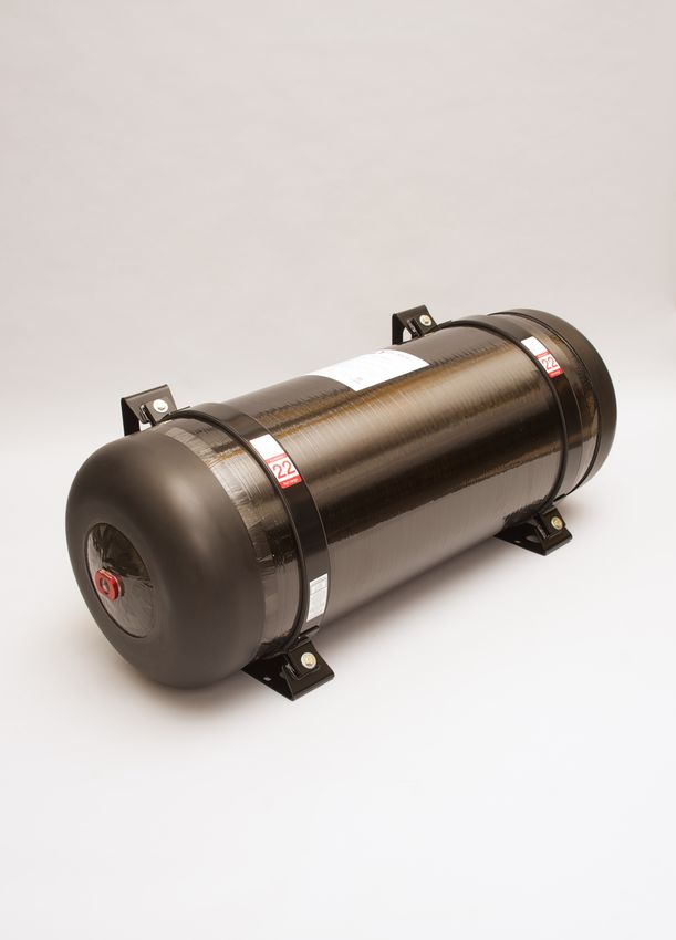
Table of Contents
         1.0      Introduction ................................................................................................................ 4
            1.1        Distribution and proper use of this manual .......................................................................... 4
            1.2        Applicability ........................................................................................................................ 4
         2.0      Product description ..................................................................................................... 5
            2.1        Cylinder identification and labels ......................................................................................... 6
         3.0      Operating conditions ................................................................................................... 8
            3.1        Gas composition .................................................................................................................. 8
            3.2        Service life ........................................................................................................................... 8
         4.0      Cylinder handling, storage and installation ............................................................... 10
            4.1        Handling ............................................................................................................................ 10
            4.2        Storage .............................................................................................................................. 10
            4.3        Preliminary inspection ....................................................................................................... 10
            4.4        Installation ........................................................................................................................ 11
               4.4.1      Cylinder installation and protection ................................................................................................... 11
               4.4.2      Mounting cylinders ............................................................................................................................. 11
               4.4.3      Strap or band or “belly” mounting ..................................................................................................... 12
               4.4.4      Neck mounting ................................................................................................................................... 13
            4.5        Valve and pressure-relief device (PRD) installation and removal........................................ 14
               4.5.1      Valve and/or plug installation............................................................................................................. 14
               4.5.2      Valve and/or plug removal ................................................................................................................. 15
               4.5.3      Pressure-relief device (PRD) ............................................................................................................... 15
         5.0      Fueling (filling) and defueling (evacuating) cylinders ................................................. 18
            5.1        Filling................................................................................................................................. 18
               5.1.1      Initial filling (fueling) ........................................................................................................................... 18
               5.1.2      Standard filling (refueling) .................................................................................................................. 19
            5.2        Defueling ........................................................................................................................... 20
         6.0      Inspection.................................................................................................................. 21
            6.1        Mounting inspection ......................................................................................................... 21
            6.2        Fuel system inspection ...................................................................................................... 21
            6.3        Cylinder inspection ............................................................................................................ 21
               6.3.1      General system inspection ................................................................................................................. 22
               6.3.2      Periodic inspection ............................................................................................................................. 23
               6.3.3      Inspection training .............................................................................................................................. 23
            6.4        Recommended equipment ................................................................................................ 24
               6.4.1      Inspection tools .................................................................................................................................. 24
               6.4.2      Cut measurement ............................................................................................................................... 25
               6.4.3      Abrasion measurement ...................................................................................................................... 26

A guide to the use, maintenance and periodic
inspection of Luxfer carbon composite AF cylinders                                                                                                                                   2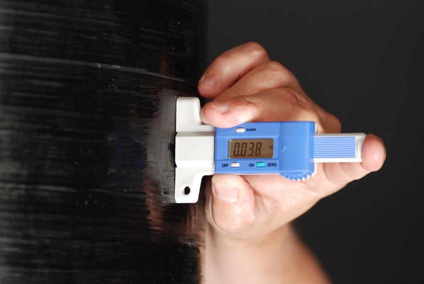
6.5        Types of damage ............................................................................................................... 28
               6.5.1       Cuts, scratches and gouges ................................................................................................................. 28
               6.5.2       Fire and heat damage ......................................................................................................................... 30
               6.5.3       Chemical attack .................................................................................................................................. 32
               6.5.4       Weathering ......................................................................................................................................... 33
               6.5.5       Abrasion .............................................................................................................................................. 33
               6.5.6       Impact damage ................................................................................................................................... 35
               6.5.7       Disbond and delamination.................................................................................................................. 36
            6.6        Leak Testing....................................................................................................................... 37
               6.5.7   Background Information on Gas Leakage and Permeation ................................................................ 37
               6.6.2   Inspection guidelines for determining gas leakage ............................................................................ 38
               6.6.2.1    Using leak detection fluid .............................................................................................................. 38
               6.6.2.2    Using a flammable gas detector .................................................................................................... 38
            6.7        Table of damage levels ...................................................................................................... 39
         7.0       Repair ....................................................................................................................... 41
            7.1        Repair tools ....................................................................................................................... 41
            7.2        Repair procedure ............................................................................................................... 41
            7.3        Repairing delamination ..................................................................................................... 44
         8.0       Destruction of condemned or expired cylinders ......................................................... 49
         9.0       Summary ................................................................................................................... 49
            9.1        Care and maintenance ....................................................................................................... 49

A guide to the use, maintenance and periodic
inspection of Luxfer carbon composite AF cylinders                                                                                                                                      3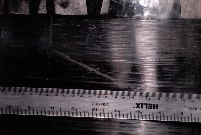
1.0 Introduction
                  Luxfer carbon composite fully wrapped (Type 3: aluminum-lined and Type 4: plastic-lined) and
                  hoop-wrapped (Type 2: aluminum-lined) cylinders are among the lightest gas cylinders available
                  for alternative fuel applications. These products, which meet the needs of many end users in
                  alternative fuel (AF) applications, offer a lightweight storage solution for compressed natural gas
                  (CNG).

                  High-pressure carbon composite cylinders are designed to be durable for the demanding usage
                  they receive. Nevertheless, like all compressed gas equipment components, cylinders must be
                  well maintained and properly used. This guide is intended to assist trained personnel in safely
                  operating, valving, installing and inspecting Luxfer composite AF cylinders.

                  You must be familiar not only with Luxfer’s instructions about properly and safely filling your
                  Luxfer composite cylinders, but also with all applicable filling guidelines, regulations, requirements
                  and laws of all appropriate local and/or national authorities and industry organizations.

                  1.1      Distribution and proper use of this manual
                           This document must be provided to all parties involved in distributing, handling, installing,
                           inspecting and using Luxfer composite AF cylinders. The manual may be reproduced to
                           provide sufficient copies for this purpose, but its contents must not be altered in any way.
                           Luxfer accepts neither responsibility nor liability for consequences resulting from
                           unauthorized alternations to this manual or for failure to follow the instructions herein.

                  1.2      Applicability
                           This manual applies to cylinders used in the storage of compressed natural gas (CNG) as
                           a vehicle fuel only and does not address all unique requirements for cylinders used to
                           store CNG for bulk transport in commerce.

              Carbon Composite Cylinder User Manual: Alternative Fuel Cylinders (ML58REV02JAN2016)

                                      Copyright © 2018 by Luxfer Inc. All rights reserved.
                                    Except as permitted under the U.S. Copyright Act of 1976
                                   and under provisions cited in paragraph 1.1, above, no part
                                      of this book may be reproduced in any form without
                                            the express written consent of Luxfer Inc.
                                               Published in the USA by Luxfer Inc.
                                        3016 Kansas Avenue, Riverside, CA 92507 USA
                                           Tel: (951) 684-5110 • Fax: (951) 781-6596
                                                    www.luxfercylinders.com

                               Luxfer Gas Cylinders is a member of Luxfer Group (NYSE:LXFR).

A guide to the use, maintenance and periodic
inspection of Luxfer carbon composite AF cylinders                                                                         4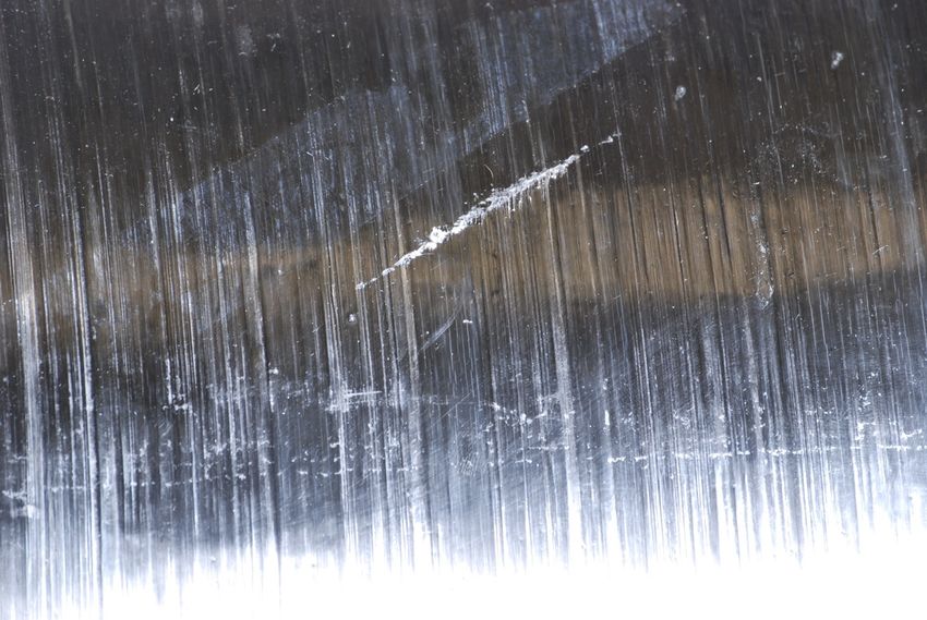
2.0 Product description
G-Stor™ Pro Type 3 AF cylinder
G-Stor™ Go Type 4 AF cylinder
A guide to the use, maintenance and periodic
inspection of Luxfer carbon composite AF cylinders 5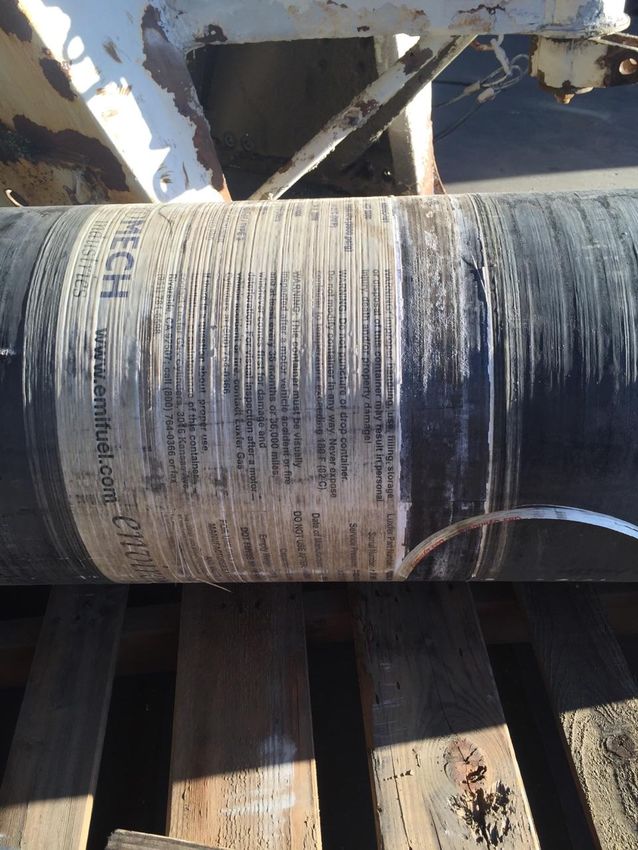
2.1 Cylinder identification and labels
CNG ONLY
Luxfer Part Number: A1159D-301
Serial Number: AIR
WARNING
Improper handling, use, filling, storage or disposal of this
Service Pressure: 24820 kPa (3600 psig) container may result in personal injury, death and/or property
at 21 C (70 F) damage!
Date of Manufacture: 10 2013 Do not puncture or drop container. Do not modify container in
DO NOT USE AFTER: 10/2033 any way. Never expose container to temperature exceeding
180ºF (82ºC).
Capacity: 111 Liters
This container must be visually inspected after a motor
Empty Weight: 100 lb. vehicle accident or fire and at least every 36 months or
36,000 miles, whichever comes first for damage and
deterioration. For visual inspection after a motor vehicle
accident or fire, contact Luxfer Gas Cylinders at (800)
DOT FMVSS 304 / NGV2-07 / TYPE 3 764-0366.
FOR USE ONLY WITH THE CONTAINER
MANUFACTURER'S APPROVED PRD AND VALVES. If there is a question about proper use,
installation, or maintenance of this container
contact Luxfer Gas Cylinders, 3016 Kansas
THE LUXFER USER MANUAL FOR ALTERNATIVE FUEL CYLINDERS IS AVAILABLE AT Ave., Riverside, CA 92507; call (800)
http://www.luxfercylinders.com/downloads/
For more information, visit the Luxfer Gas Cylinders website at www.luxfercylinders.com or call Luxfer customer
764-0366 or fax (951) 781-6598.
service at (800) 764-0366, Fax (951) 781-6598.
Example: NGV2/FMVSS 304 label.
CNG ONLY
DO NOT USE AFTER 2033/10
Luxfer Part Number: A2173C-101
Serial Number: AHF
Service Pressure: 20.0 MPa / 15 C
Test Pressure: 30.0 MPa
Date of Manufacture: 2013/10
Capacity: 250 Liters
Empty Weight: 90.3 Kg
ECE R 110 CNG-3
110 R-000250 2009/11
FOR USE ONLY WITH THE CONTAINER
MANUFACTURER'S APPROVED PRD AND VALVES.
EMER PRD200 / MARK SERIES - Torque: 217 10 N-m
VTI PRD K905 / RV200 - Torque: 134 4 N-m
THE LUXFER USER MANUAL FOR ALTERNATIVE FUEL CYLINDERS IS AVAILABLE AT
http://www.luxfercylinders.com/downloads/
For more information, visit the Luxfer Gas Cylinders website at www.luxfercylinders.com or call Luxfer customer
service at (800) 764-0366, Fax (951) 781-6598.
Example: ECE R110 label.
A guide to the use, maintenance and periodic
inspection of Luxfer carbon composite AF cylinders 6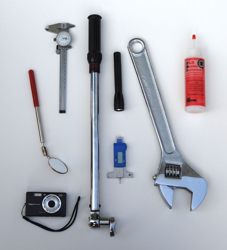
CNG ONLY
Luxfer Part Number: A2843D-101 WARNING
Serial Number: AJB Improper handling, use, filling, storage or disposal of this
Service Pressure: 24820 kPa (3600 psig) container may result in personal injury, death and/or property
at 21 C (70 F) damage!
Date of Manufacture: 11 2012 Do not puncture or drop container. Do not modify container in
DO NOT USE AFTER: 11/2015 any way. Never expose container to temperature exceeding
Capacity: 282 Liters 180ºF (82ºC).
Empty Weight: 165 lb. This container must be visually inspected after a motor
vehicle accident or fire and at least every 36 months or
36,000 miles, whichever comes first for damage and
deterioration. For visual inspection after a motor vehicle
DOT FMVSS 304 / TYPE 4 accident or fire, contact Luxfer Gas Cylinders at (800)
764-0366.
FOR USE ONLY WITH THE CONTAINER
MANUFACTURER'S APPROVED PRD AND VALVES. If there is a question about proper use,
installation, or maintenance of this container
contact Luxfer Gas Cylinders, 3016 Kansas
THE LUXFER USER MANUAL FOR ALTERNATIVE FUEL CYLINDERS IS AVAILABLE AT Ave., Riverside, CA 92507; call (800)
http://www.luxfercylinders.com/downloads/
For more information, visit the Luxfer Gas Cylinders website at www.luxfercylinders.com or call Luxfer customer
764-0366 or fax (951) 781-6598.
service at (800) 764-0366, Fax (951) 781-6598.
Example: FMVSS 304 ONLY label.
A guide to the use, maintenance and periodic
inspection of Luxfer carbon composite AF cylinders 7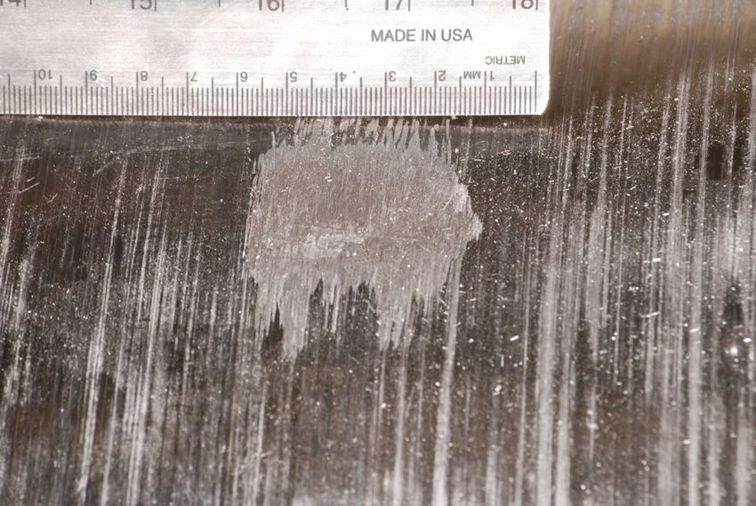
3.0 Operating conditions
                  Operating conditions include the pressure, temperature, gas type and environment in which the
                  cylinder is used. Various standards provide multiple cylinder operation pressures and
                  temperatures for different applications and gas services. The best source of pressure and
                  temperature limits is the cylinder label for each individual product. Please refer to those
                  guidelines and contact Luxfer Gas Cylinders with any questions.

                  WARNING: An over-pressure condition can occur as a result of filling to service pressure
                  in cold weather. As temperature increases, the pressure will increase and the settled
                  condition could exceed the service pressure. Temperature must always be considered and
                  compensated for during filling.

                  3.1      Gas composition
                           Luxfer carbon composite AF cylinders are designed and approved for storage of natural
                           gas for use as a motor vehicle fuel. The natural gas used must comply with:
                           Recommended Practice for Compressed Natural Gas Vehicle Fuel, SAE J1616;
                           Canadian General Standards Board Standard for Natural Gas for Vehicles, CGSB 3.513;
                           an equivalent national standard; and/or as shown below.

                                    Dry Gas - Water vapor would normally be limited to less than 32 mg/m3
                                    (2 lbs/MMscf), a pressure dewpoint of -9ºC (16ºF) at 20 700 kPa (3,000 psi).
                                    There would be no maximum constituent limits for dry gas, except for:

                                     1. Hydrogen Sulfide                       23 mg/m3
                                     2. Oxygen                                 1.0 percent by volume
                                     3. Hydrogen                               2.0 percent by volume

                                    Wet Gas - Gas that contains 32 mg/m3 (2 lbs/MMscf) of water or more normally
                                    meets the following maximum constituent limits:

                                     1. H2S and other soluble sulfides        23 mg/m3 (1 gr/100scf)
                                     2. Total Sulfur                          115 mg/m3 (5 gr/MMscf)
                                     3. Oxygen                                1 percent by volume
                                     4. CO2                                   3 percent by volume
                                     5. Hydrogen                              0.1 percent by volume

                                    Under wet gas conditions, a minimum of 1 mg of compressor oil per kilogram of
                                    gas (0.007 grains of compressor oil per pound of gas) is necessary to protect
                                    metallic containers, liners and bosses.

                  3.2      Service life
                           Luxfer carbon composite AF cylinders have a maximum service life as defined by the
                           country of use or the design standard to which they are built. The service life of a cylinder
                           can be determined from the “Do not use after” designation on the cylinder label.

A guide to the use, maintenance and periodic
inspection of Luxfer carbon composite AF cylinders                                                                         8
WARNING: NEVER use a cylinder past the “Do not use after” date. Personal injury
                           or death may result.

                           If a label is unreadable, an inspector or user can determine the cylinder serial number
                           from the end-plug label or stamping on the liner neck. Contact Luxfer Gas Cylinders and
                           provide the serial number to learn the final date of use and to obtain replacement labels.
                           When the service life stated on the label has been reached, the user must remove the
                           cylinders from service. Cylinders removed from service must be disabled or destroyed in
                           accordance with applicable regulations.

A guide to the use, maintenance and periodic
inspection of Luxfer carbon composite AF cylinders                                                                      9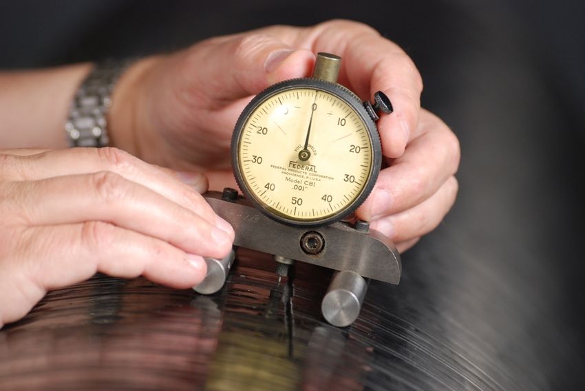
4.0 Cylinder handling, storage and installation
                  Use the following guidelines to install Luxfer AF cylinders into vehicles.

                  4.1      Handling

                           To prevent cylinder damage, Luxfer recommends the following:

                               •    Only handle AF cylinders with appropriate lifting devices and equipment that will
                                    not cause damage.
                               •    Do not walk on cylinders! Walking on cylinders can cause level 2 damage.
                               •    Do not handle cylinders with internal pressure above 3 bar (40 psi).
                               •    Do not drag, drop or roughly handle cylinders.
                               •    Protect cylinder labels to ensure legibility.
                               •    When transporting a valved cylinder, protect the valve and properly secure the
                                    cylinder. Never handle cylinders by their fittings, valves, pressure relief devices or
                                    piping.

                  4.2      Storage

                           Luxfer cylinders must be stored in a dry environment away from direct sunlight (UV
                           radiation), chemicals, heat sources and corrosive environments. Prevent cylinders and/or
                           assemblies from rolling or moving. Protect cylinders from any contaminants and damage.
                           Luxfer recommends storing cylinders in their original shipping packaging.

                           Cylinders should not be stored completely unpressurized. If a cylinder is stored
                           unpressurized at very low temperatures, moisture condensation and contamination could
                           damage the cylinder. Install plugs and/or valves and O-rings intended for use according
                           to the valve manufacturer’s recommendations. Store cylinders with a small positive
                           pressure (not less than 25 psi and not more than 40 psi) of a dry inert gas or natural gas.

                  4.3      Preliminary inspection

                           Before beginning any installation, visually inspect the cylinder for damage caused by
                           shipping and handling. If no damage is found, proceed with installation. If damage is
                           found or suspected, complete a thorough visual inspection (see Section 6) before
                           installing the cylinder.

A guide to the use, maintenance and periodic
inspection of Luxfer carbon composite AF cylinders                                                                           10
4.4 Installation
4.4.1 Cylinder installation and protection
When the cylinder is installed on a vehicle, use shielding to protect the cylinder
from damage caused by road debris and contact with vehicle components and
cargo. The preferred shielding is open mesh, which not only protects the cylinder,
but also permits easy reading of cylinder labels.
To prevent cylinder damage:
• Avoid direct contact between the shielding and the cylinder.
• Avoid trapping solid debris or liquids between the shielding and the
cylinder.
• Avoid cylinder contact with vehicle components (e.g., brake lines, etc.).
• Avoid exposure to vehicle heat.
• Avoid exposure to harmful liquids and gases.
• Avoid prolonged exposure to sunlight.
4.4.2 Mounting cylinders
Various mounting methods may be used with Luxfer cylinders. The mounting
method and appropriate mounting hardware are often specified by the system
manufacturer and may be supplied by Luxfer. While typical, the sample mounting
methods and parts list shown below are provided for general information only
and do not overrule or supersede requirements of system manufacturers or
specific instructions provided either by system manufacturers or Luxfer for
particular mounting configurations. Refer to applicable instructions and
specifications provided by the system manufacturer before attempting to mount
cylinders.
Cylinders used to store natural gas as vehicle fuel and bearing NGV2 or
FMVSS304 markings should be installed in accordance with NFPA 52
requirements.
When installing a cylinder in an underbody configuration, give proper
consideration to damage that could occur from impact with large objects. Luxfer
carbon composite cylinders should be shielded not only from road debris, but
also from impact with curbs, high traffic bumps, deep potholes, pavement
protrusions and large objects in the road that could damage cylinders and cause
hazardous situations.
CAUTION: During pressurizing and de-pressurizing of a composite
cylinder, it is normal for the cylinder to expand and contract. The chosen
mounting system must allow for this expansion and contraction; otherwise,
damage to the cylinder and fuel storage system may occur.
A guide to the use, maintenance and periodic
inspection of Luxfer carbon composite AF cylinders 114.4.3 Strap or band or “belly” mounting
Figure 4.4.3a
Minimum dimensions: A = 25mm (0.984”), B = 1/3 of cylinder length
PARTS LIST
ITEM DESCRIPTION
1 Composite cylinder
2 Belly mounting strap
3 Rubber strip†
If a cylinder is sufficiently long or heavy to require more than two brackets during
installation, follow the bracket manufacturer’s installation guidelines. Brackets
should be installed 6 to 8 inches apart near the cylinder ends. Do not use one
bracket in the center and one on each end; this may lead to damage of brackets
and/or the cylinder.
Figure 4.4.3b
Vertical mounting of a cylinder with straps is not permitted. The cylinder may
slide out of the straps due to gravity and vibration and cause damage to the fuel
system components and/or the cylinder, which could cause personal injury or
death.
Any straps or bands used to secure a cylinder must not induce a pressure on the
outer surface of the cylinder greater than 3.45MPa (500 psi) at any cylinder fill
pressure.
A guide to the use, maintenance and periodic
inspection of Luxfer carbon composite AF cylinders 12CAUTION: When using the strap or “belly” mounting method, a strip of
rubber must be installed between the cylinder and metal straps to protect
the carbon composite exterior of the cylinder. The mounting should also be
sufficiently flexible to allow for longitudinal cylinder expansion and
contraction.
NOTE: Optional Luxfer-approved straps are offered, for an additional charge,
with all Luxfer G-Stor™ Go strap-mount cylinders. Luxfer-approved straps are
specifically designed for use with Luxfer cylinder diameters to allow for hoop
expansion during fill. Luxfer assumes no responsibility for any damage that
occurs as a result of improper cylinder installation with non-approved straps.
4.4.4 Neck mounting
Figure 4.4.4
PARTS LIST
ITEM DESCRIPTION
1 Composite cylinder
2 Fixed neck block
3 Sliding neck block
4 Bearing
5 Bolt
6 Washer(s) (optional)
Visually inspect end-mounting blocks regularly for signs of corrosion and
premature wear. When lubrication of the neck block is required, use an
aluminum-compatible, silicon-based lubricant.
Vertical mounting of Luxfer cylinders is authorized only when neck mounts are
used. Care should be taken in the design of the neck mount, because the weight
of the cylinder will be completely on one block. If the cylinder is vertically
mounted, ample room must be allowed for any valves, plugs, tubing or other
components to ensure there is no rubbing or abrasion of the cylinder or
components.
A guide to the use, maintenance and periodic
inspection of Luxfer carbon composite AF cylinders 134.5 Valve and pressure-relief device (PRD) installation and removal
Use only approved valves and pressure-relief devices that comply with applicable
standards and regulations (e.g., NGV 3.1 and PRD-1). Contact Luxfer for a list of
approved valves and PRDs (or pressure-relief devices).
WARNING: Do not use valves or pressure-relief devices that have not been tested
and approved by Luxfer.
4.5.1 Valve and/or plug installation
Inspect the valve in accordance with the valve manufacturer’s recommendations
prior to installation. Do not install any valve that has not passed such an
inspection.
WARNING: Do not use valves or pressure-relief devices that have not been
tested and approved by Luxfer.
Valve threads must be free from damage. Visually inspect threads to ensure that
the mating surface of the valve is smooth and free from damage.
Not all O-ring materials are compatible with all gases. To ensure that the O-ring
material being used is suitable for natural gas service, follow the
recommendations of the valve manufacturer or use an O-ring supplied by the
manufacturer. The natural gas industry generally recognizes Nitrile (also called
Buna N), with a 70 – 90 Durometer hardness, as the standard O-ring material. If
you have questions, please contact the system manufacturer, the valve
manufacturer or Luxfer.
Check to make sure that the O-ring groove and threads in the cylinder are clean
and free from debris and damage. Install a new O-ring on the valve or plug in
accordance with the valve or plug manufacturer’s recommendations. Luxfer
recommends lubricating the O-ring prior to installation with a lubricant compatible
with the O-ring and natural gas (unless the valve or plug manufacturer specifies
otherwise). For any O-ring sold by Luxfer, or an O-ring on a Luxfer brand valve or
plug, only use Krytox GPL 100 oil or Krytox GPL 200 grease. Never use
Molykote 55 or other lubricant, which may cause O-ring failure.
For installation of a Luxfer brand valve, refer to the Luxfer operation manual S-
OP-MPV for installation instructions and proper torque values. For installation of
a Luxfer brand plug, follow the installation and torque guidelines as stated in this
section.
Apply a small amount of aluminum-compatible, silicon-based lubricant to the
bottom three valve threads, taking care not to apply lubricant to the bottom face
of the valve body. Only a thin application of lubricant is necessary—too much
lubricant can cause sealing problems.
Insert the valve into the cylinder neck and tighten it by hand to make sure threads
are properly aligned. Then tighten the valve to the torque value recommended by
the valve manufacturer.
A guide to the use, maintenance and periodic
inspection of Luxfer carbon composite AF cylinders 14Note: Some valve manufacturers may require special or specific tools for valve
installation; if so, using a standard wrench could damage the valve or valve
connections. Follow valve manufacturer instructions.
Note: Valve torque guidelines in the table below are provided for general
information only and do not overrule or supersede valve manufacturers’ torque-
level recommendations, which should be used in preference to the values shown.
Table 1—Valve torque guidelines
PARTS LIST
Thread Min. N-m (ft.lb.) Max. N-m (ft.lb.)
1.125 – 12 UNF 167 (123) 186 (137)
4.5.2 Valve and/or plug removal
Follow the system manufacturer’s guidelines to depressurize the system.
Following the recommendations of the system manufacturer or valve
manufacturer, ensure that the cylinder is completely empty before attempting to
remove the valve and/or plug. Luxfer recommends removal of the valve before
attempting removal of any plugs. Removal of a plug while under pressure can
lead to serious injury or death.
WARNING: If the valve is hard to remove, STOP! If you suspect for any
reason that a valve may be defective, do not attempt to remove the valve—
because a valve that is damaged or not functioning properly may cause
you to think erroneously that the cylinder is empty when you do not hear
gas being released. Handle all valved cylinders—even those you think are
empty—as if they were under pressure! To check whether a hard-to-remove
valve is functioning properly, add to the cylinder a small amount of the gas
specified on the cylinder label to prove that gas actually goes in and out of
the valve. If the valve works properly during this check, fully depressurize
the cylinder and then carefully remove the valve. If you have questions
about valve function or require further instructions, contact the valve
manufacturer.
Once the valve and/or plug is removed, inspect it thoroughly if it will be reused in
the installation or another installation. Check valve and/or plug threads for
damage and inspect cylinder threads to verify that they are clean-cut and
undamaged. Clean and inspect the cylinder O-ring gland (groove) to verify that
there is no damage.
REJECT cylinders with damaged threads.
REJECT cylinders with O-ring gland damage that prevents an effective,
safe seal.
4.5.3 Pressure-relief device (PRD)
Use only approved pressure-relief devices that comply with applicable standards
and regulations (e.g., PRD-1). Contact Luxfer for a list of approved PRDs and
PRD configurations.
A guide to the use, maintenance and periodic
inspection of Luxfer carbon composite AF cylinders 15Some PRDs are integrated into the valve, while others must be installed
A B
separately. If a vent line is required to vent gas away from the cylinder, take note
that no valves or flow restrictions are allowed anywhere in the inlet or outlet flow
path of a PRD. Below are sample PRDs installation methods.
Single PRD configuration—Where only a single PRD is required, use one of
the following configurations approved by Luxfer for the specific cylinder model
being considered:
CNG valve with an integrated PRD
Valve with a retrofitted PRD
Separate end-plug PRD
Double PRD configuration—There are three possible configurations for double
PRDs:
(1) A valve either with an integrated PRD or an installed PRD plus a separate
end-plug PRD. (2) A valve with a PRD that has been piped to the center of the
cylinder plus a separate end-plug PRD. (3) Two PRDs piped from either the
valve or the plug of the cylinder and centrally located along the length of the
cylinder.
Multiple (more than two) PRD configuration—Figure 4.5.3 (below) is an
example of a cylinder configured with three PRDs—one integrated in the valve, a
second end-plug PRD in the opposite cylinder end and a third, L-shaped PRD
piped from the valve to a central position. Additional T-shaped PRDs could also
be installed in series along the pipe from the valve.
Figure 4.5.3
Shared PRDs—Some fuel systems can have multiple cylinders plumbed to a
single PRD or set of PRDs; these are generally plumbed either from end plugs of
multiple cylinders or from valves of multiple cylinders. Contact Luxfer for more
information about approved configurations for shared PRDs.
A guide to the use, maintenance and periodic
inspection of Luxfer carbon composite AF cylinders 16General guidelines that apply to all PRD installations:
• Ensure that threads are undamaged.
• Clean threads thoroughly.
• Dry threads and ensure that the area is free from debris.
• Select the proper O-ring or copper-crush washer specified by the PRD
manufacturer. Do not reuse copper-crush washers or O-rings. Always
use a new copper-crush washer or O-ring; failure to do so may cause a
leak.
• Remove the used copper-crush washer or O-ring before replacing the
PRD. Do not double-stack copper-crush washers or O-rings.
• If recommended by the PRD manufacturer, apply lubricant to the O-ring
or copper-crush washer.
• Place the O-ring or copper crush-washer properly on the fitting, being
careful not to damage the O-ring or copper crush-washer.
• Thread the fitting into the mating surface.
• Apply the proper installation torque recommended by the PRD
manufacturer.
A guide to the use, maintenance and periodic
inspection of Luxfer carbon composite AF cylinders 175.0 Fueling (filling) and defueling (evacuating) cylinders
The following procedures apply for initial fueling (filling), re-fueling, and defueling (evacuation) of
cylinders.
Note: During fueling (filling) and defueling, expansion or contraction of the cylinder sometimes
causes snapping or popping noises. This is normal and is not a cause for concern.
WARNING: Rapid flow of gas can generate a static electrical charge, which can ignite
escaping gas. Therefore, the cylinder, attached components (including the vent pipe used
for defueling) and vehicle must be connected to a ground for purging, fueling (filling) and
defueling (evacuating).
Prior to filling the cylinder, it is important to understand the characteristics and hazards of natural
gas, including explosion, fire and asphyxiation.
Fuel (fill), defuel (evacuate) and purge all systems in a well-ventilated area that is free from
possible ignition sources, including (but not limited to) open flames, electric sparks and static
electricity.
WARNING: When working with flammable gases in a confined area, always use gas-
monitoring equipment.
5.1 Filling
WARNING: Always remove all oxidants (including air) from a cylinder prior to
filling the cylinder with flammable gas! Failure to remove oxygen or other oxidants
from the cylinder before filling with natural gas can create a combustible mixture
that can ignite and cause serious injury or death. Be alert to the fact that air may
enter the cylinder whenever the cylinder has been vented or exposed to ambient
pressure, including during initial filling, after valve installation or any time the
system has been bled to zero pressure.
5.1.1 Initial filling (fueling)
WARNING: Failure to follow the fuel system manufacturer’s instructions on
filling may lead to serious injury or death!
An “initial fill” is the first pressurization that occurs after the cylinder has been
vented or exposed to ambient pressure, including initial filling, after valve
installation or any time the system has been bled to zero pressure. Before filling
a cylinder with natural gas, the cylinder must be purged of any oxidants. Failure
to purge any oxidants can create a combustible mixture that can ignite and lead
to serious injury or death. Do not perform the purge operation or the initial filling
of a Luxfer G-Stor Go cylinder if the cylinder has been stored in an environment
at or below 0F (-18°C). Allow the cylinder to warm up to room temperature, 60°F
or greater, before attempting to purge or fill an empty cylinder.
Follow the fuel system manufacturer’s guidelines to purge the system before the
initial fueling, if required, or use the following procedure to purge any oxidants
A guide to the use, maintenance and periodic
inspection of Luxfer carbon composite AF cylinders 18before filling the cylinder with CNG. The following is a guideline to safely remove
or reduce any oxidants (including oxygen from air) in the cylinder.
Guideline:
1. Ensure that the cylinder is grounded and in a well-ventilated area.
2. Pressurize the cylinder or assembly to at least 5 bar (72.5 psi) with dry
nitrogen.
3. The cylinder or assembly is now ready to be pressurized with CNG.
During the initial filling of a cylinder that has been purged of oxidants, fill with
natural gas to a pressure of at least 50 psi. If the cylinder is filled to a pressure
less than 50 psi with natural gas, there is still a potential to create a flammable
mixture that could ignite.
During the initial filling of a Luxfer G-Stor Go cylinder, it is TYPICAL and
NORMAL to experience AIR LEAKAGE through the composite reinforcement.
During manufacture, air collects between the internal polymer liner and the
carbon composite when it is unpressurized. During its first pressurization, the
trapped air is forced out. Escaping air will be most noticeable where the metal
end hardware meets with the composite. However, air leakage may be noticed in
other locations as well. It usually takes between 10 to 45 minutes for trapped air
to escape. This is not a defect or leak of the cylinder.
5.1.2 Standard filling (refueling)
If the residual pressure in the cylinder is less than 300 psi and the
cylinder/vehicle has been stored in an environment that is 0°F (-18°C) or lower
do not fill the cylinder. Bring the cylinder and/or vehicle inside and allow the
cylinder to warm up to 60°F or higher before filling. If the residual pressure is
higher than 300 psi, the cylinder may be filled as long as the temperature is
above -40°F (-40°C).
WARNING: Fill the cylinder such that the settled pressure does not exceed
the marked service (working) pressure at 21°C (70°F). Never fill the cylinder
greater than 1.25 times the marked service pressure immediately after
filling, regardless of the temperature.
A guide to the use, maintenance and periodic
inspection of Luxfer carbon composite AF cylinders 195.2 Defueling
WARNING: When working with flammable gases in a confined area, always use
gas-monitoring equipment and ground (earth) all equipment.
Follow the fuel system manufacturer’s guidelines for venting CNG from the system.
Otherwise, if possible, the preferred method of de-fueling is to run the engine. Note that
some residual pressure will likely remain in cylinders and will need to be vented. During
defueling, make sure pressure is sufficiently low that those performing the procedure will
not be harmed if gas escapes due to a leak or broken seal. However, defueling pressure
must be slightly higher than atmospheric pressure to stop air from entering the cylinder
if a seal is broken. Vent gas properly through a flue or flare stack to prevent
contaminating the environment and to avoid a potentially hazardous gas accumulation.
Always make sure that all equipment is properly grounded. Use caution and avoid any
uncontrolled ignition sources during any defueling operation.
A guide to the use, maintenance and periodic
inspection of Luxfer carbon composite AF cylinders 206.0 Inspection
Using proper equipment and safety apparatus, inspect cylinders routinely to determine whether
damage has occurred. Before beginning any inspection, remove all dirt and debris from the
cylinder. If necessary, you may use a mild soap-and-water solution. Do not use solvents, harsh
cleaners or abrasives. Always carefully inspect cylinders if a vehicle has been involved in an
accident.
6.1 Mounting inspection
Ensure that all mounting blocks, brackets and other components are in good condition
and properly secured. If any mountings are loose, re-tightened them by following
procedures specified by the fuel system manufacturer. If a mounting is damaged, you
must conduct a re-certification inspection. If parts are missing or need replacement,
please contact the fuel storage system manufacturer.
6.2 Fuel system inspection
CAUTION: Never allow air or debris to enter a cylinder. When disconnecting
fittings (seals) during maintenance or inspection, make sure that air or debris do
not enter through the opening.
Fuel system inspection includes checking all attached components, such as valves,
tubing, end plugs, fittings and pressure-relief devices. During inspection, make sure that
each device is securely attached. If any is loose, tighten it in accordance with the fuel
system manufacturer’s instructions. If any component is missing, contact the fuel storage
system manufacturer and do not put the system back into service.
6.3 Cylinder inspection
IMPORTANT: The Luxfer-recommended “accept” and “reject” criteria provided in
this manual do not replace or supersede any criteria established by regulatory
authorities either now or in the future.
Alternative fuel cylinders are designed and manufactured for a limited design life, which is
indicated on the cylinder label. Always check the label first to ensure that the cylinder has
not exceeded its expiration date.
REJECT and remove from service any cylinder that either lacks a label containing
mandatory information or has a label that has become illegible. If you can
positively determine that Luxfer produced such a cylinder and you know the
cylinder serial number, contact Luxfer for disposition instructions.
A guide to the use, maintenance and periodic
inspection of Luxfer carbon composite AF cylinders 21Inspect for the following conditions during periodic inspection:
• Cuts, scratches and gouges
• Fire and heat damage
• Chemical attack
• Debonding
• Delamination
• Weathering
• Abrasion
• Impact damage
Inspection Type Inspection Description Inspection Frequency Qualification
Performed by the Recommended every 3 Performed by the
operator, driver, months or at specified operator, driver,
maintenance personnel, maintenance intervals maintenance personnel,
or other service depending on operating or other service
technician. It is primarily conditions. technician. Review of this
General Inspection. a visual inspection to cylinder manual is
ensure that the cylinder, recommended.
mounting and plumbing
are in good condition
and remain secure.
Performed by trained Check with local authority Luxfer or External
personnel who are and cylinder label, but is Training Certificate in
certified in accordance most commonly Fuel Storage System and
with local authority. It is performed immediately Cylinder Inspection.
Detailed Visual a more in-depth after installation, then
Inspection. examination of the every 3 years or 36,000mi
cylinder, mounting and (58,000km), whichever
plumbing and evaluates comes first.*
system code
compliance.
*Detailed Visual/Requalification inspection intervals specified by local authorities and standards may be more or less than 3 years.
Recommended inspection intervals also vary with operating conditions.
6.3.1 General system inspection
This inspection, usually performed by a driver, maintenance person or service
technician, is a basic visual inspection to ensure that the cylinder and mountings
are in good condition. The inspection includes, as a minimum, examining the
mounting system, cylinder and plumbing, as well as checking for gross leaks and
damage.
Perform this inspection at least every three months under normal operating
conditions and more frequently during more demanding conditions.
A guide to the use, maintenance and periodic
inspection of Luxfer carbon composite AF cylinders 226.3.2 Periodic inspection
This is an in-depth examination of the cylinder, mounting system and plumbing
for external damage and deterioration, including the cylinder surface under the
support straps. A competent agency or person approved or recognized by
applicable regulatory authorities must conduct the inspection in accordance with
all applicable regulations and Luxfer specifications. Under normal operating
conditions, perform the inspection every three years or 36,000 miles, whichever
comes first. In addition, you must perform a recertification inspection following
any accident or fire, as well as at the time of any reinstallation. (This
recertification inspection is mandatory under most CNG cylinder and system
standards; however, the prescribed frequency may vary from standard to
standard.)
IMPORTANT: For the lifetime of a cylinder, records of all periodic
recertification inspections and testing should be sent to Luxfer along with
materials, test certificates and inspection reports relating to the
manufacture of the cylinder. Such record-keeping is required by regulatory
authorities.
6.3.3 Inspection training
Luxfer Gas Cylinders offers inspection training either at its AF facilities in
Riverside, California, on site at customer locations or periodically at special
training venues (watch www.luxfercylinders.com for announcements of upcoming
training sessions).
A guide to the use, maintenance and periodic
inspection of Luxfer carbon composite AF cylinders 236.4 Recommended equipment
6.4.1 Inspection tools
A mirror and a flashlight are helpful when you are inspecting hard-to-reach areas.
Bubbling leak-detection fluid is also useful. (Optional: A digital camera can be
used to document damaged areas.) Fill out an inspection report form (available
from Luxfer.) If a cylinder is irreparably damaged, apply a “Danger: Failed
Cylinder Inspection” label to cylinder. If the cylinder passes inspection, apply a
label showing the date of the inspection.
A guide to the use, maintenance and periodic
inspection of Luxfer carbon composite AF cylinders 246.4.2 Cut measurement
Cut measurement—First calibrate the depth gauge to zero on the undamaged
cylinder surface.
Then measure the depth of the cut.
A guide to the use, maintenance and periodic
inspection of Luxfer carbon composite AF cylinders 256.4.3 Abrasion measurement
Abrasion measurement—Calibrate the depth gauge to zero on the undamaged
cylinder surface (left), then measure the depth of the abrasion at the deepest point (right).
A guide to the use, maintenance and periodic
inspection of Luxfer carbon composite AF cylinders 26 You may also use a digital depth gauge. A guide to the use, maintenance and periodic inspection of Luxfer carbon composite AF cylinders 27
6.5 Types of damage
6.5.1 Cuts, scratches and gouges
These are easily spotted on carbon composite cylinders. Watch for fiber lifting
and unraveling caused by cuts transverse to the direction of the fiber wrapping.
Level 1 cut
Level 2 cut
A guide to the use, maintenance and periodic
inspection of Luxfer carbon composite AF cylinders 28 Level 3 cut
Fiber lifting and unraveling
Inspection method—Inspect cuts, scratches and gouges for depth and length.
Measure depth either with a dial indicator-type depth gage or depth caliper.
Measure length with a graduated scale or ruler.
Reference: Table and repair method.
The maximum allowable depth and length for this type of damage is found in the
table of damage levels in Section 6.6; immediately remove from service and
A guide to the use, maintenance and periodic
inspection of Luxfer carbon composite AF cylinders 29condemn any cylinder with unacceptable damage according to this table. The
appropriate repair method is found in Section 7 for cylinders that are capable of
being repaired.
Note: Some Luxfer cylinders have a fiberglass and resin coating over the label or
the entire surface. This fiberglass and resin layer is cosmetic only and not
structural in nature. Therefore, any damage to the fiberglass should be
considered Level 2, as long as there is no evidence that the damage extends into
the carbon, and can be repaired according to the repair procedures specified in
Section 7. Damage to the fiberglass layer can be cuts, gouges, abrasion, fiber
unravelling or any combination thereof. Any impact damage, evidence of heat or
fire or evidence of chemical attack should be carefully evaluated as this may still
be level 3 damage.
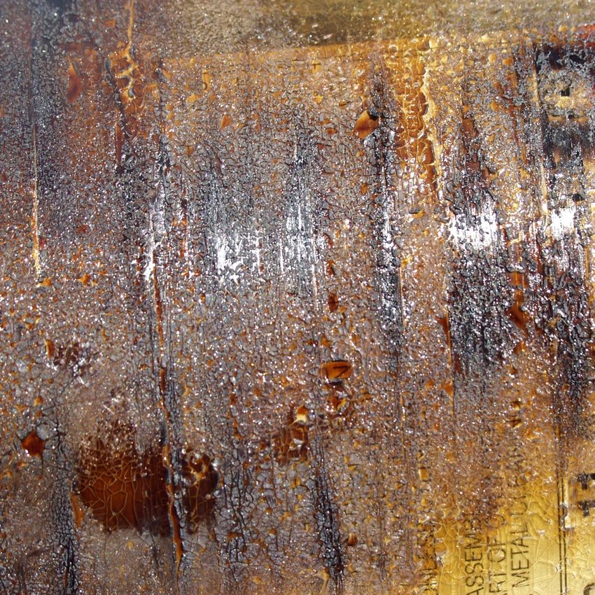
6.5.2 Fire and heat damage
Heat damage—Elevated heat exposure, which is a different condition than
obvious heat or fire damage, may or may not result in permanent damage to the
cylinder. Elevated heat exposure occurs when the cylinder itself (apart from any
outer protection) has been subjected to a temperature in excess of the glass-
transition temperature or softening point of the composite material (expressed as
Tg).
A composite cylinder is not intended for normal use in any environment resulting
in prolonged composite overwrap temperatures in excess of 82°C (180°F).
Prolonged temperatures in excess of the Tg of the composite may cause
discoloration of the resin system. This discoloration may range from a light
golden caramel color to a deep brownish-black burnt appearance. Harmless
natural aging—i.e., light discoloration of the external coating, usually a yellowing
over time due to continued direct exposure to sunlight—is not the result of
harmful temperature exposure.
A guide to the use, maintenance and periodic
inspection of Luxfer carbon composite AF cylinders 30Usually the degree and depth of resin discoloration are dependent on the
temperature, the duration of exposure or a combination of both. The higher the
temperature, or the longer the duration of exposure to a lower temperature, the
darker the resin system will become.
If you are uncertain about the cause of resin discoloration, contact Luxfer for
guidance.
Fire damage—Charring or melting of the composite material, decals, valves or
other attachments is evidence of fire damage. Full or partial activation of the PRD
is also evidence of fire or excessive heat. Flame impingement may result in the
resin burning away from the cylinder exterior, leaving loose carbon fibers.
Fire Damage
Inspection method—Visually inspect the entire surface of the cylinder for
evidence of burnt or charred composite material. Also inspect any valves and
attachments for evidence of extreme heat.
Reference: Table and repair method.
A guide to the use, maintenance and periodic
inspection of Luxfer carbon composite AF cylinders 31Cylinders showing light discoloration of the resin, but not showing evidence of
extreme heat exposure (e.g., melting of decals, charring or heat damage to
mounting attachments or PRD activation), may be returned to service without
repair. If you are not sure whether cylinder discoloration is the result of elevated
temperature exposure or harmless natural aging, contact Luxfer for guidance.
WARNING: Immediately remove from service any cylinder involved in a
motor vehicle collision or fire.
Immediately REJECT and CONDEMN any cylinder showing melting or charring
of composite material or attachments. No repair is possible for this condition. See
Section 7.0 for procedures on condemning the cylinder.
6.5.3 Chemical attack
Chemicals, including battery acid (to which AF cylinders may be exposed), may
dissolve, corrode, soften, remove or ruin cylinder materials; they may also cause
bubbling, pitting or extreme dulling of the resin or create multiple fractures
transverse to the direction of the fiber. When solvents are involved, the cylinder
surface may become sticky when touched.
Chemical attack
Inspection method—Visually inspect the entire surface of the cylinder for this
condition.
Immediately REJECT and CONDEMN any cylinder with such damage.
A guide to the use, maintenance and periodic
inspection of Luxfer carbon composite AF cylinders 326.5.4 Weathering
Weathering is a change in the surface appearance of composite material or
exposed aluminum surfaces resulting from environmental exposure to sunlight,
road salts and extreme heat and cold. Exposure to sunlight can discolor the
composite over time; this is usually characterized by a yellowish color in the
exposed area (see “Heat and fire damage,” Section 5.5.2). Road salts may
corrode exposed aluminum, but this does not usually cause damage to
composite material. Extreme heat or cold may cause mild discoloration of the
composite or craze-cracking of the surface resin.
Inspection method—Visually inspect the entire surface of the cylinder for
weathering. Discoloration or craze cracking of the resin is classified as Level 1
damage and does not require repair. If corrosion of exposed aluminum is found,
contact Luxfer.
Reference: Table and repair method.
6.5.5 Abrasion
Abrasion, or localized wearing away of composite material, occurs when a
cylinder rubs against other components such as mounting brackets, the vehicle
structure, shielding, etc.
Level 1 abrasion
A guide to the use, maintenance and periodic
inspection of Luxfer carbon composite AF cylinders 33 Level 2 abrasion
Level 3 abrasion
Inspection method—Visually inspect the entire surface of the cylinder for
evidence of abrasion. Pay close attention to areas around mounting straps or
other attachments.
Reference: Table and repair method.
Refer to Table 6.6 for damage limits for abrasion. Immediately REJECT and
CONDEMN any cylinders with unacceptable damage according to this table. The
A guide to the use, maintenance and periodic
inspection of Luxfer carbon composite AF cylinders 34appropriate repair method is found in Section 7 for cylinders that are capable of
being repaired.
6.5.6 Impact damage
Impact damage may appear as hairline cracks in the exterior resin, cuts,
abrasion and indentation of the surface of the aluminum liner.
Inspection method—Visually inspect the entire surface of the cylinder for
evidence of impact damage. Carefully evaluate all impact sites according to the
following criteria:
LEVEL 1: Light impact damage that does not require repair. It usually consists
of a small area where the composite is frosted. Where impact results in cuts or
abrasion, evaluate these features according to the table of damage levels in
Section 6.6 for the maximum area allowed for Level 1 damage. Cylinders with
Level 1 damage can usually be returned to service.
LEVEL 3: Severe damage in which impact has caused a large area of frosting
(including cuts or abrasion), damage to fibers in the cylinder dome, liner denting
A guide to the use, maintenance and periodic
inspection of Luxfer carbon composite AF cylinders 35or other major structural damage. REJECT and CONDEMN a cylinder exhibiting
such damage. Refer to table of damage levels in Section 6.6 for Level 3 impact,
cut or abrasion damage limits.
Reference: See table of damage levels in Section 6.6.
6.5.7 Disbond and delamination
Disbond is physical separation between composite layers (most often a
separation between glass and carbon layers). Usually caused by impact, disbond
appears as a whitish region.
Delamination is the separation of composite layers, but it differs from disbond in
that cut fibers are evident. Delamination is usually caused by severe impact.
Reference: See table of damage levels in Section 6.6. The appropriate repair
method is found in Section 7 for cylinders that are capable of being repaired.
A guide to the use, maintenance and periodic
inspection of Luxfer carbon composite AF cylinders 366.6 Leak Testing
6.5.7 Background Information on Gas Leakage and Permeation
Prior to inspecting Luxfer G-Stor Go cylinders for leakage, it is important to
understand the difference between leaks, permeation and trapped air escaping
from the composite.
The following definitions and inspection procedure will help inspectors distinguish
between normal permeation levels and rejectable leaks.
Trapped air: Cylinders that are filled when new or after being vented may expel
air that is trapped between the liner and the composite overwrap. While this may
appear as leakage, this is normal and will stop after several minutes. Trapped air
may be expelled from the composite or around the outer surface of the neck, or
both.
Do not continue to fill cylinders if gas escaping is audible. See Fueling Cylinders
in Section 5.1
Permeation: Permeation can occur with Type 4 cylinders. This is normal and
often will result in a detectable level of natural gas. Permeation may escape
through the composite in one or more locations.
Luxfer designs, manufactures and tests our cylinders in accordance with industry
standards. Allowable limits for permeation are defined in these standards and are
verified during testing. Permeation limits are based on a cylinder’s volume. As a
result, larger cylinders may show more evidence of detectable gas than smaller
ones.
Leakage: Each G-Stor Go cylinder Luxfer produces is checked for leakage prior
to being packed for shipment. Leakage will not occur under normal service
conditions, however damage or abuse from extreme service conditions could
cause a leak to form.
Verify leakage using the inspection procedure that follows. Leakage can be
distinguished from permeation by:
• Audible hissing – usually from the cylinder dome area
• Vigorous and sustained bubbling of leak detection fluid forming a raised
foam on the cylinder surface. (Note this can also happen when a cylinder
is filled from zero or near-zero pressure. See Trapped Air note above.)
• Rapid reaction of flammable gas detector when held several inches away
from the area. See leak detection procedure below.
If you suspect a leak, vent the cylinder using the procedure in Section 5.2. Do not
defuel the system by running the engine! Contact Luxfer for further instructions.
A guide to the use, maintenance and periodic
inspection of Luxfer carbon composite AF cylinders 37You can also read