GEOGRAPHICAL ISLANDS FLEXIBILITY DELIVERABLE D3.1 ENTERPRISE SERVICE BUS SPECIFICATIONS
←
→
Page content transcription
If your browser does not render page correctly, please read the page content below
Ref. Ares(2019)7933227 - 31/12/2019

                       Geographical Islands FlexibiliTy

                                    Deliverable D3.1
                   Enterprise Service Bus Specifications

Organisation:       Intracom Telecom
Main authors: Isidoros Kokos (ICOM), Iasonas Kouveliotis-Lysikatos (ICOM), Ilias
Lamprinos (ICOM), Nikos Ioannidis (ICOM)
Contributors: Luc Richaud (Odit-e), Michel Clémence (Odit-e), Ricardo Cartaxo (RDN),
Gonçalo Luís(RDN), Nuno Pinho da Silva (RDN), Lizhen Huang (NTNU), Sverre
Stikbakke (NTNU), Erling Onstein (NTNU), Saso Brus (INEA)

                                                                                  Date 31/12/2019

   This project has received funding from the European Union’s Horizon 2020 research and innovation
                               program under grant agreement No 824410.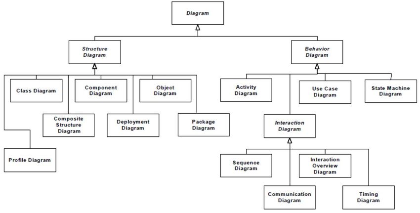
DELIVERABLE 3.1 – VERSION 1.0
                                     WORK PACKAGE N° 3

 Nature of the deliverable
 R           Document, report (excluding the periodic and final reports)                              X
 DEM         Demonstrator, pilot, prototype, plan designs
 DEC         Websites, patents filing, press & media actions, videos, etc.
 OTHER       Software, technical diagram, etc.

 Dissemination Level
 PU    Public, fully open, e.g. web                                                                  X
 CO    Confidential, restricted under conditions set out in Model Grant Agreement
 CI    Classified, information as referred to in Commission Decision 2001/844/EC

 Quality procedure
 Date                      Version                      Reviewers                   Comments
 2019-11-15                Deliverable TOC              ICOM
 2019-12-06                Deliverable 1st Draft        ICOM, NTNU, RDN, ODI
 2019-12-13                Deliverable Draft for Q&A    TRIALOG
                           process review
 2019-12-19                Final Version                ICOM

ACKNOWLEDGEMENTS
The project Geographical Islands FlexibiliTy (GIFT) has received funding from the European Union’s Horizon
2020 research and innovation programme under grant agreement No 824410. The sole responsibility for the
content of this publication lies with the authors. It does not necessarily reflect the opinion of the Innovation
and Networks Executive Agency (INEA) or the European Commission (EC). INEA or the EC are not responsible
for any use that may be made of the information contained therein.
More information on the project can be found at http://www.gift-h2020.eu/

COPYRIGHT
© GIFT Consortium. Copies of this publication – also of extracts thereof – may only be made with reference
to the publisher.

                                                                                                              1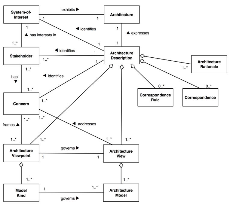
EXECUTIVE SUMMARY
GIFT is an innovative project that aims to decarbonise the energy mix of European islands, launched in 2019.
Its objective is to develop innovative systems to facilitate islands integrating vast amount of renewable
energy sources, reducing their needs for fossil fuel generation and relevant greenhouse gases emissions.

This report documents the technical specifications of the Enterprise Service Bus (ESB), the system integrating
the different software artefacts of the GIFT’s project technical solution, at the level of the control centre. The
ESB interconnects applications and services that will be implemented in the project, as well as legacy
applications and services through standard interfaces.

The work presented in this report is guided from relevant work realized in the context of the project:
deliverable D2.1 “Use-cases, architecture definition and KPIs definition”, which provided a high-level
description on the use of the ESB to facilitate the realization of the Use Cases (UCs) of GIFT project;
deliverable D2.2 “Requirement relevant to demonstrators”, which documented specific requirements for the
ESB with regards to interoperability, security, privacy and performance; deliverable D2.3 “Technical and
Business Flows” (restricted to the consortium), which documented the ground work on the interactions
among the components of GIFT’s technical solution and elaborated the elicitation of ESB’s requirements.

The documentation of the specifications follows the paradigm of international standards related to the
design of software systems (i.e. ISO/IEC/IEEE 42010:2011, IEEE Std 1016™-2009) organizing the design in
different views and viewpoints, as a mechanism for the separation of concerns among the different
stakeholders having an interest in the system. The different viewpoints identified are documented in the
report, detailing which concerns they aim to address and the method of communicating the design. Unified
Modelling Language (UML) notation was utilized in most occasions for documenting the design.

Initially a high-level architectural description is presented (Context View), detailing interactions of the ESB’s
with the rest of the components of GIFT’s solution, as well as with external systems (i.e. legacy systems of
DSO and external data providers). This “static” view presents possible information flows among the different
elements of the architecture and aims to provide the broader context of the system. Following the high-level
design, the functional specification are presented (Functional View), detailing the main functionalities of the
ESB and its interfaces. The design is communicated via the use of different type of UML diagrams (i.e. Use
Case diagram, Sequence diagram, Component diagram). Based on the requirements imposed by the various
components of the project, the functionalities of the ESB were decomposed to the main functions presented
in this view, in the form of a Use Case (UC) analysis. The documented UCs have a generic scope, meaning
they can be mapped to the different components of GIFT’s architecture. For tackling concerns related to the
operation of the system (e.g. with regards to service invocation, user/role management) its internal logic and
processes are elaborated to the reader (Process View), through the use of UML Activity diagrams.

Finally, different design aspects concerning interoperability, security, privacy and performance of the
solution that need to be considered in the detailed design of the solution are presented.

This document aimed at providing a high-level design of the ESB, tackling the requirements documented in
the work realized thus far in the project. This design will evolve to a finer-grain towards the next phase of the
project, guiding the implementation phase, as well as tackling any pilot specific concerns that will occur (e.g.
related to system deployment).

                                                                                                                2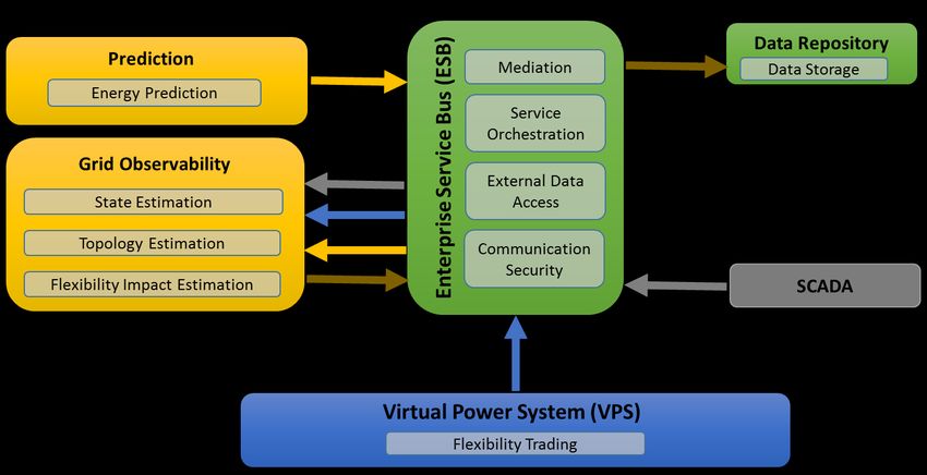
TABLE OF CONTENTS
ACKNOWLEDGEMENTS ............................................................................................................................................... 1
COPYRIGHT ............................................................................................................................................................... 1
EXECUTIVE SUMMARY ........................................................................................................................................... 2
TABLE OF CONTENTS ................................................................................................................................................... 3
LIST OF FIGURES .......................................................................................................................................................... 4
LIST OF TABLES ............................................................................................................................................................ 4
1. INTRODUCTION .................................................................................................................................................. 5
1.1.   SCOPE OF THE DOCUMENT ........................................................................................................................................ 5
1.2.   GIFT PROJECT ....................................................................................................................................................... 5
1.3.   ACCRONYMS AND ABBREVIATIONS ............................................................................................................................. 6
2. METHODOLOGY .................................................................................................................................................. 7
2.1.   APPROACH ............................................................................................................................................................ 7
2.2.   NOTATION ............................................................................................................................................................ 9
3. DESIGN VIEWS .................................................................................................................................................. 10
3.1.       CONTEXT VIEW .................................................................................................................................................... 10
     3.1.1.     High-Level Architecture ........................................................................................................................... 10
     3.1.1.     External Systems Information Flows ....................................................................................................... 11
     3.1.2.     GIS Twin Information Flows .................................................................................................................... 12
     3.1.3.     Prediction Information Flows .................................................................................................................. 12
     3.1.4.     Grid Observability Information Flows ..................................................................................................... 13
     3.1.5.     Key Performance Indicators Flows .......................................................................................................... 13
3.2.       FUNCTIONAL VIEW ............................................................................................................................................... 14
     3.2.1.     Use Case Model ....................................................................................................................................... 14
     3.2.2.     Interfaces ................................................................................................................................................ 22
3.3.       PROCESS VIEW ..................................................................................................................................................... 23
     3.3.1.     Concepts.................................................................................................................................................. 23
     3.3.2.     Processes ................................................................................................................................................. 24
4. DESIGN ASPECTS ............................................................................................................................................... 26
4.1.       INTEROPERABITY................................................................................................................................................... 26
4.2.       SECURITY ............................................................................................................................................................ 26
     4.2.1.     Authentication/Authorisation ................................................................................................................. 26
     4.2.2.     Encryption ............................................................................................................................................... 26
     4.2.3.     Audit Log ................................................................................................................................................. 26
     4.2.4.     Alarms ..................................................................................................................................................... 26
4.3.       PRIVACY ............................................................................................................................................................. 26
4.4.       PERFORMANCE .................................................................................................................................................... 27
5.      NEXT STEPS ....................................................................................................................................................... 27
6.      REFERENCES ...................................................................................................................................................... 27

                                                                                                                                                                                3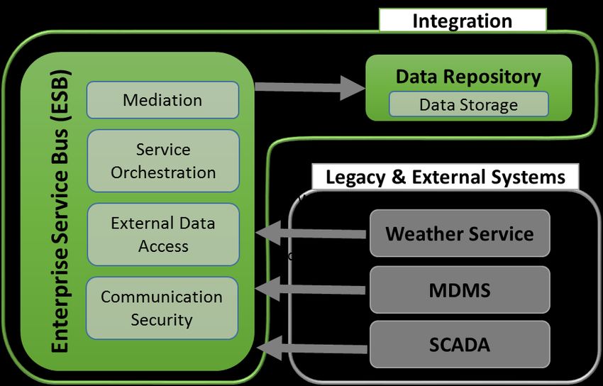
LIST OF FIGURES
Figure 1 Conceptual model of an architecture description according to [4] ..................................................... 7
Figure 2 UML Diagram Types [6] ........................................................................................................................ 9
Figure 3 Context Diagram .................................................................................................................................11
Figure 4 External Systems Information flow diagram ......................................................................................12
Figure 5 GIS Twin Information flow diagram ...................................................................................................12
Figure 6 Prediction Information flow diagram .................................................................................................13
Figure 7 Grid Observability Information flow diagram ....................................................................................13
Figure 8 Key Performance Indicators Information flow diagram .....................................................................14
Figure 9 UML Use Case Diagram: Use Cases of ESB .........................................................................................15
Figure 10 UML Sequence Diagram: Invoke Service (pull data) ........................................................................17
Figure 11 UML Sequence Diagram: Invoke Service (push data).......................................................................18
Figure 12 UML Sequence Diagram: Invoke Process .........................................................................................19
Figure 13 UML Sequence Diagram: Publish Event ...........................................................................................20
Figure 14 UML Sequence Diagram: Service Registration .................................................................................21
Figure 15 UML Sequence Diagram: Process Registration ................................................................................22
Figure 16 UML Component diagram: ESB’s Interfaces.....................................................................................22
Figure 17 UML Activity Diagram: Service Call ..................................................................................................24
Figure 18 UML Activity Diagram: Process Call ..................................................................................................25

LIST OF TABLES
Table 1 Invoke Service - Pull data scenario: Actor mapping ............................................................................17
Table 2 Invoke Service - Push data scenario: Actor mapping ..........................................................................18
Table 3 Publish Event: Actor mapping .............................................................................................................20
Table 4 ESB’s Interface List ...............................................................................................................................23

                                                                                                                                                            4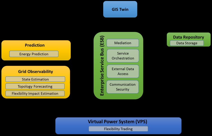
1. INTRODUCTION

1.1. SCOPE OF THE DOCUMENT

The goal of this report is to provide the technical specifications of the Enterprise Service Bus (ESB), the system
integrating the different software artefacts of the GIFT’s project technical solution at the level of the control
centre. The ESB interconnects applications and services that will be implemented in the project, as well as
legacy applications and services through standard interfaces.

The document is intended to address a diverse audience. The main target group is GIFT project’s consortium,
providing on one hand a high-level design as a guideline for the implementation of the ESB solution; on the
other, guiding the phases of integration and testing of the ESB with the other technical solutions of the
project. Furthermore, given the public nature of the document, the authors aimed at addressing a wider
audience, such as: domain stakeholders (e.g. DSOs, microgrid operators), interested in using a similar
solution; Smart Grids domain experts (either academic researchers or industrial partners), interested in the
specification of such a solution; requirements and systems engineers in general, interested in the
development of integration solutions in the SG domain.

The specification presented in this report is guided from relevant work realized in the context of the project.
More specifically, on:

    1. Deliverable “D2.1 Use-cases, architecture definition and KPIs definition” [1], which provided a high-
       level description on the use of the ESB to facilitate the realization of the Use Cases (UCs) of GIFT
       project;

    2. Deliverable “D2.2 Requirement relevant to demonstrators” [2], which documented specific
       requirements for the ESB with regards to interoperability, security, privacy and performance;

    3. Deliverable “D2.3 Technical and Business Flows” [3], which documented the ground work on the
       interactions among the components of GIFT’s technical solution and elaborated the elicitation of
       ESB’s requirements.

The readers of this report shall find details tackling the area with regards to the design of the ESB solution:

    •   Methodology followed for presenting the design (Chapter 2);

    •   High-level architectural description with regards to ESB’s interactions (Section 3.1);

    •   Functional specification (Section 2.2, Section 2.3);

    •   Design aspects of the solution (Chapter 4).

1.2. GIFT PROJECT

GIFT is an innovative project that aims to decarbonise the energy mix of European islands, launched in 2019.
Its objective is to develop innovative systems to facilitate islands integrating vast amount of renewable
energy sources, reducing their needs for fossil fuel generation and relevant greenhouse gases emissions.
Through the development of multiple innovative solutions, such as a virtual power system, energy
management systems for harbours, factories, homes, better prediction of supply and demand and

                                                                                                                  5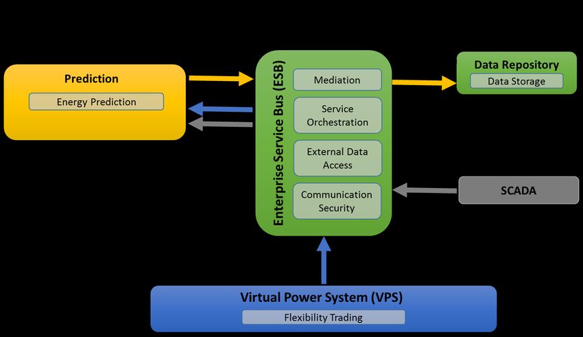
visualisation of those data through a GIS platform, and innovative storage systems allowing synergy between
electrical, heating and transportation networks.
During the 4 years of the project, the solution will be developed and demonstrated in two lighthouse islands,
in Hinnøya, Norway’s largest island and the small island of Procida in Italy whilst a replicability study the
replicability study of the solution we be done for the Greek and Italian islands at minimum, (respectively Evia
and Favignana).

1.3. ACCRONYMS AND ABBREVIATIONS

      Term                                                 Definition
 AMQP              Advanced Message Queuing Protocol
 API               Application programming interface
 BRP               Balance Responsible Party
 CDM               Canonical Data Model
 CIM               Common Information Model
 DSO               Distribution System Operator
 EAI               Enterprise Application Integration
 EMS               Energy Management System
 ESB               Enterprise Service Bus
 FTP               File Transfer Protocol
 GDPR              General Data Protection Regulation
 GIS               Geographic Information System
 HTTP              Hypertext Transfer Protocol
 IEC               International Electrotechnical Commission
 IEEE              Institute of Electrical and Electronics Engineers
 ISO               International Organization for Standardization
 OMG               Object Management Group
 MDMS              Meter Data Management System
 RES               Renewable Energy Sources
 REST              Representational state transfer
 SCADA             Supervisory Control and Data Acquisition
 SFTP              SSH File Transfer Protocol
 TLS               Transport Layer Security
 TSO               Transmission System Operator
 UC                Use-Case
 UML               Unified Modelling Language
 VPP               Virtual Power Plant
 VPS               Virtual Power System

                                                                                                             6
2. METHODOLOGY
This chapter presents the methodology followed for presenting the design of the ESB, which follows the
concepts of view/viewpoints.

2.1. APPROACH

The design of a system is a conceptualization showcasing its essential characteristics, whilst demonstrates a
means to fulfil its requirements. The documentation of the design in the form of specification facilitates the
analysis of the system and aims to guide the implementation phase.
In the process of architecture design, ISO/IEC/IEEE 42010:2011 “Systems and software engineering—
Architecture description” [4] provides a guideline on the methodology for the architecture description of
systems. According to the standard, an architecture description may be organized in different views using
viewpoints, providing a mechanism for the separation of concerns among the stakeholders, while at the same
time providing the description of the whole system that is fundamental to the notion of architecture.
The ISO/IEC/IEEE 42010:2011 standard provides a conceptual model which defines the formal constituents
for description of a system’s architecture, as presented in [4].

                    Figure 1 Conceptual model of an architecture description according to [4]
Similar concepts are utilized in standard IEEE Std 1016™-2009 “IEEE Standard for Information Technology--
Systems Design--Software Design Descriptions” [5], identifying the concept of design view, governed by the
concept of design viewpoint.
An attempt to provide a consolidated explanation of this terminology would be the following:
    •   A viewpoint describes how certain stakeholders - with a particular concern - interpret the system;
    •   A view is a representation of a whole system from the perspective of a related set of concerns, in
        accordance with a viewpoint.

                                                                                                            7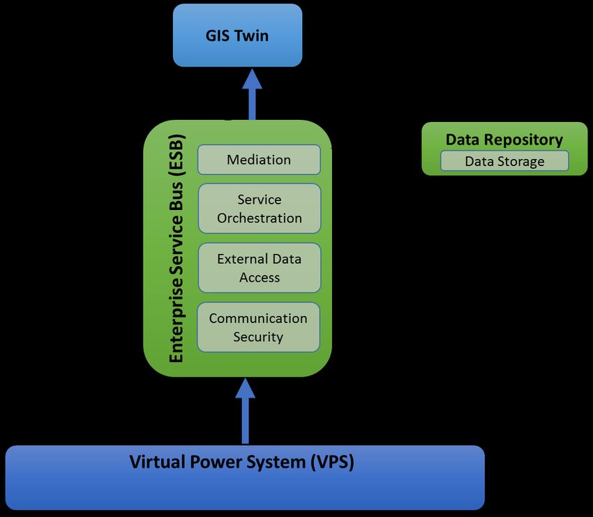
In order to address the concerns of the design and implementation of ESB solution, the viewpoints/view
approach was followed. Base on the concerned expressed thus far in the project, the following viewpoints
were identified1.

                                      Context Viewpoint
    Description          Providing a broader context of the system—relationships and
                         dependencies with other components of the GIFT solution as well as
                         external systems. Presents a static view of possible information flows
                         among them.

    Interested           All
    Stakeholders

    Concerns             Describing the system and interaction with the environment

    View Models          Data flow diagram (not UML)

                                     Functional Viewpoint
    Description          A viewpoint representing main functionality of the system and its
                         interfaces.

    Interested           Individuals associated with the development/integration of the
    Stakeholders         system.

    Concerns             Describing the components residing in the system and their
                         associated interfaces.

    View Models          UML Use Case Diagram, UML Sequence Diagram, UML Component
                         Diagram

                                      Process Viewpoint
    Description          A Viewpoint presenting part of the internal logic of the system and its
                         processes.

    Interested           Individual associated with the development/integration of the
    Stakeholders         system.

    Concerns             Describing the main concepts of the internal logic of the system.

    View Models          UML Activity Diagram

1
  It must be noted that the list doesn’t include some typical viewpoints involved in system design, such as the
deployment viewpoint. The list of viewpoints was based on concerns documented in the current phase of project and
relevant information for such concerns were not yet available.

                                                                                                               8
2.2. NOTATION
A variety of modelling languages are available for describing a system. Unified Modelling Language (UML) is
a general-purpose modelling language offering graphical language for visualizing, identifying, constructing
and documenting the objects of a software system. This language provides a standard way to describe a
system, including conceptual features such as business processes and system functions, as well as specific
elements such as programming languages, database schemas, and reusable software components. UML has
been adopted as a model by the Object Management Group (OMG), which has been managing it since then.
In 2005, it was also published as an ISO standard. It was adopted for the description of the system considering
criteria such as maturity, sufficiency to communicate the structure and semantics and tailor ability.
The following three key concepts form the basis of UML:
• Elements, that is, the elements of a system;
• Relationships, among the entities of the system;
• Charts that represent entities & relationships.
Figure 2 UML Diagram Types [6]
There are two general categories of diagrams:
• Structure diagrams showing important elements of the software structure or a system in general;
• Behaviour diagrams show the dynamic behaviour of software components or a system in general and
describe what should happen during its operation.
The different types of diagrams from the two categories of UML diagram are presented in Figure 2, whilst
more details on the nature of each diagram can be found in [7].
UML was preferred for describing both the static (e.g. component diagrams), as well as the dynamic aspects
(e.g. Activity/Sequence diagrams) of the system. Non-UML diagrams were also elaborated to communicate
the design at a higher level of abstraction (section 3.1).
93. DESIGN VIEWS
3.1. CONTEXT VIEW
3.1.1. High-Level Architecture
A high-level view of ESB’s requirements via its interactions with the rest of the components of GIFT solution
and external systems is presented in this section.
The ESB is a middleware that aims to provide message transformation and routing capabilities along with
other features that allow seamless integration among enterprise applications. The ESB can act as a
coordinator of the data exchange between different systems: the ones to be implemented in project; third
party IT systems such as weather service providers; and legacy systems of the DSOs, such as the SCADA, the
MDMS, etc. It can also offer orchestration of the execution of the complex business process which might
relate to the components of GIFT solution.
An ESB is the mean by which service-oriented IT ecosystems connect service consumers with service
providers, offering functionalities such as call routing, multicasting, message and communication protocol
transformation enabling integration at the enterprise domain. Such a solution poses an excellent tool in the
SG domain, since it can facilitate the transition of domain stakeholders (such as Microgrid Operators, Virtual
Power Plant Operators and DSOs) closer to the notion of a service-oriented architecture, including reusability,
visibility, flexibility and business alignment.
The important benefits of this middleware concern the loose coupling of applications, integration facilitation
through single point of communication, the use of standard interfaces & protocols, as well as its scalability
and advanced monitoring capabilities. Contrary to more traditional enterprise application integration (EAI)
approaches of monolithic stacks (such as hub and spoke architecture), the ESB - based on the bus concept
found in hardware architecture- enables a distributed deployment.
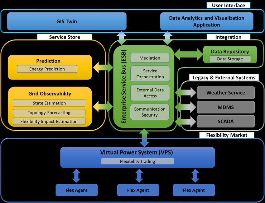
In Figure 3, a high-level diagram illustrates the different components of GIFT solution, their main interactions
and functionalities. The diagram depicts only the information flows related to the ESB, whilst other flows
might be realized among GIFT components in the overall solution. The different components and a short
description of their role are presented in the following list:
• Data Analytics and Visualization Application (DAV): An application presenting a GUI for custom
visualisations of the project’s KPIs;
• Data Repository: A solution for the short-term or long term storage of data from external systems
as well as information generated by the different solutions of the project;
• Enterprise Service Bus: The system under design. A platform dealing with the integration of GIFT‘s
components, handling the mediation of messages among components, the orchestration of complex
business processes as well as interfacing external systems (e.g. Weather Service, MDMS);
• Flex Agent: Device for extraction, trading and executing of flexibilities;
• Grid Observability: Software used to build an empirical model of the distribution grid, based on
historical data of smart meters and of the SCADA system. Among the functionalities provided by this
component are the forecasting of the grid‘s state (voltage in grid node), its topology, as well as the
estimation of the impact of flexibility;
• GIS Twin: A twin system of the GIS of the DSO, incorporating the functionalities of GIFT project;
• Meter Data Management System (MDMS): A system of the DSO or Meter Operator (MO) providing
energy measurement data from SM installed in the distribution grid;
10• Supervisory Control and Data Acquisition (SCADA): A system of the DSO providing real time
measurement data from equipment installed in the distribution grid;
• Prediction: Software used to predict the energy supply and demand;
• Virtual Power System (VPS): Decentralised automatic trading platform, connecting flexibility
providers (e.g. consumers, producers, prosumers), intermediaries (e.g. Aggregators, VPPs) and
flexibility procurers (e.g. BRPs, DSOs, TSOs).
The following subsections present an instantiation of the above high-level architecture, for different
functionalities realized, providing a static representation of the information flow; meaning the time
aspect/sequence of the flows of the information objects is not presented.
Figure 3 Context Diagram
3.1.1. External Systems Information Flows
As presented in Figure 4, the ESB receives data from external systems (i.e. MDMS, SCADA and Weather
Service) and forwards them to the Data Repository for storage. These flows might involve transformation of
the data from the format of the external systems.
11Figure 4 External Systems Information flow diagram
3.1.2. GIS Twin Information Flows
Figure 5 presents the information flows of GIS Twin via ESB, which concern the KPIs, Grid State and the Energy
Prediction, which are accessed from the Data Repository as well as information related to flexibility and
prosumers’ status provided by the VPS.
Figure 5 GIS Twin Information flow diagram
3.1.3. Prediction Information Flows
12The following figure presents the information flows from/to ESB for the realisation of a prediction function.
Different information flows occur from VPS and Data Repository, towards the Prediction component, whilst
a reverse flow towards the Data Repository provides the result of prediction for storage.
Figure 6 Prediction Information flow diagram
3.1.4. Grid Observability Information Flows
Figure 7 presents the information flows from ESB for the realisation of a Grid Observability function. Different
information flows occur from VPS, Data Repository and Prediction, towards the grid observability
component, whilst a reverse flow with the Grid State and Estimated Topology towards the Data Repository,
provides the result for storage.
Figure 7 Grid Observability Information flow diagram
3.1.5. Key Performance Indicators Flows
13The following figure presents the KPI flows from the various components of the system - through the ESB -
to the Data Repository for storage.
Figure 8 Key Performance Indicators Information flow diagram
3.2. FUNCTIONAL VIEW
This section presents the system’s functionalities and primary interactions. A Use Case (UC) model including
detailed sequence diagrams was selected as a mean of presenting the functionalities of the ESB. This decision
was based on the fact that the utilization of the system by the different components of GIFT follows a pattern,
given it acts as a facilitator of information exchanges among them.
The services offered through ESB might vary in scope e.g. data storage, data retrieval, trigger of a calculation
process and asynchronous response with the results. For instance, in the context of the project this might
concern the Prediction module requesting consumption measurement data from the MDMS or the Data
Repository or “pushing” the predictions (upon calculation) to the Grid Observability module - via the ESB.
The realisation of the above transactions presupposes that all external systems are authenticated users of
the ESB, that the ESB has a registered service for storing data from a service provider and that the requestor
of the service has the authority/permission to access this service.
Based on the requirements imposed by the various components of the project, the functionalities of the ESB
were decomposed to the main functions presented in this section, in the form of UCs. The UCs have a generic
scope with regards to the actors and service type provided; meaning they can be mapped to the different
components of GIFT’s architecture.
3.2.1. Use Case Model
The following actors were identified, with regards to the UC analysis:
• The Service Provider: A simple user of the ESB, utilizing the ESB for providing a service;
• The Service Requestor: A simple user of the ESB, utilizing the ESB for requesting a service;
14• The Publisher: A simple user of the ESB(specialisation of Service Provider), utilizing the ESB for
publishing data to multiple receivers;
• The Subscriber: A simple user of the ESB (specialisation of Service Requestor), utilizing the ESB for
subscribing to the data provided by a Publisher;
• The Admin User: A superuser of the ESB, managing the system, able to register services and
processes and monitor their operation.
Figure 9 UML Use Case Diagram: Use Cases of ESB
A non-exhaustive use case list presenting the main functionalities of the ESB, follows:
• Invoke Service: Presents the main functionality of the ESB, mediating among the Service Provider and
the Service Requestor. Two scenarios were identified one for „pulling“ and one for „pushing“ data;
15• Invoke Process: An additional functionality of the ESB, enabling multicasting as well as orchestration
of more complex business processes. Processes manage the invocation of registered or external
services and return the “aggregated” result to the requestor;
• Register Service: Functionality related to the registration of as service to the ESB from a Service
Provider;
• Register Process: Functionality related to the registration of as process to the ESB from a Service
Requestor;
• Publish Event: Functionality related to the communication of an event to multiple subscribers;
• Authorise Request: Secondary functionality, involving the authorisation of a request following the
permission of the requestor. Reused by the above functions;
• Authentication: Involves the authentication of actors communicating with the ESB, for receiving a
token which enables them to use the rest of the ESB’s functionalities.
A UC diagram for the visualisation of the above, is presented in Figure 9.
3.2.1.1. Invoke Service
The main functionality of the ESB is the mediation of communications among a Service Provider, offering a
service through the ESB and the Service Requestor in need of accessing the service. Two scenarios are
identified:
• Pulling data from the ESB;
• Pushing data through the ESB.
Preconditions
• Service Requestor and Service Provider are registered users of the ESB;
• The requested service of Service Provider is registered in the ESB;
• Service Requestor has the information on how to invoke the relevant service;
• Service Requestor has the authority to access the service.
3.2.1.1.1. Pull Data from Service
A sequence diagram communicating the first scenario and the steps of accessing a service for retrieving data
offered via the ESB is presented in Figure 10. The Service Requestor needs to be initially authenticated by the
ESB using personalized credentials. Upon successful authentication, a token is returned which is used in
future communications with the ESB for authorisation purposes. Using this token in a following request, along
with a service (unique) name and the request’s parameter, the Service Receiver is validated in terms of
authority for accessing the requested service. If the token is invalid - meaning the session has timed out or
the requestor doesn’t have the authority to access the service - an error message is returned. Otherwise, the
Service Provider is communicated from the ESB, and the response is returned to the original requestor.
16Figure 10 UML Sequence Diagram: Invoke Service (pull data)
A possible mapping of actors with regards to GIFT solution might involve the following:
Service Requestor(s) Service Provider Information
Prediction, Grid Observability,
Data Repository Consumption Data
GIS Twin
Grid Observability Data Repository Energy Prediction
GIS Twin, Prediction Data Repository Grid State
Prediction Data Repository Estimated Topology
Prediction Data Repository Weather Data
Grid Observability, Prediction,
VPS Scheduled Flexibility
GIS Twin
Data Analytics and Visualization
Data Repository KPI
Application
Table 1 Invoke Service - Pull data scenario: Actor mapping
173.2.1.1.2. Push Data to Service
The mechanism for pushing data is similar to the one presented in previous section, whilst in this case the
original request is for providing rather than retrieving data.
As presented in Figure 11, the Service Requestor, upon successful authentication to the ESB, invokes an ESB
service, providing consumption data for storage. The ESB checks the authority of the request and upon
success invokes the service of the Service Provider for storing the information.
Figure 11 UML Sequence Diagram: Invoke Service (push data)
A possible mapping of actors with regards to GIFT solution might involve the following:
Service Requestor Service Provider Information
Grid Observability Data Repository Grid State,
Estimated Topology
All Components Data Repository KPI
Table 2 Invoke Service - Push data scenario: Actor mapping
3.2.1.2. Invoke Process
This functionality intents to offer a user of the ESB with the ability to orchestrate a business process for
invoking more than one services, which might also involve some pre-processing or post-processing steps.
18Such an example is pushing energy prediction data upon calculation from Prediction both to Grid
Observability and to Data Repository, via the ESB. Another example might be requesting weather forecasting
data from an external weather service and storing them to the Data Repository.
As presented in Figure 12, the ESB has a registered process which is invoked by the service requestor,
providing the proper request parameters. The ESB initiates the process and does the assigned pre-processing
of the request before invoking the first service (of Service Provider 1). Upon return of the response and any
processing involved in the process description, another request is formulated and sent (to Service Provider
N). The ESB, upon receiving the last response, performs a processing function (if registered in the process)
and returns the aggregated result to the original requestor.
Figure 12 UML Sequence Diagram: Invoke Process
Preconditions
• Service Requestor and Service Providers are registered in the ESB;
• The requested services of Service Providers are registered in the ESB;
• A process is registered in the ESB involving the invocation of the services and processing related
information
• Service Requestor has the information on how to invoke the relevant service;
• Service Requestor has the authority to access the service.
3.2.1.3. Publish Event
In the case where multiple clients (subscribers) are interested in a specific information flow (aka event), e.g.
measurements from real-time sensing equipment of SCADA, the ESB offers an interface for the realisation of
this multicasting operation.
19As presented in the figure below, the Publisher utilizes the ESB for providing an event. The ESB will broadcast
this event to all Subscribers of this event type (aka message topic).
Preconditions
• Publisher and Subscriber are registered users of the ESB;
• The publishing of the event is registered in the ESB;
• Subscriber has the authority to receive the event.
Figure 13 UML Sequence Diagram: Publish Event
A possible mapping of actors with regards to GIFT solution is presented in the following table:
Publisher Subscriber(s) Information
SCADA Grid Observability, Real-time Grid Data
Prediction
Prediction Data Repository, Energy Prediction
Grid Observability
Table 3 Publish Event: Actor mapping
3.2.1.4. Service Registration
All services provided by the ESB must be registered through the process described in this section.
As presented in the sequence diagram of Figure 14, in an initial step, a Service Provider2 requests
authentication. Upon successful authentication the service provider invokes the registration service of ESB
for registering its service, providing the service description and the token (from the authentication). The ESB
validates the token and the service description and if successfully registers the service, provides a success
message with the unique identifier of the service. This unique identifier can be used by third parties to access
the newly registered service through the domain of the ESB, given the proper permissions are assigned.
2
It could also be the administrator of the ESB (Admin User) who registers the service.
20Preconditions
• Service Provider is a registered user of the ESB
Figure 14 UML Sequence Diagram: Service Registration
3.2.1.1. Process Registration
The ESB provides the ability to create and manage processes, involving one or multiple steps of service
invocation. This UC describes how a process is registered in the ESB.
As presented in Figure 15, in an initial step, the Admin User3 is authenticated. Upon successful authentication
the user invokes the ESB’s process registration service, providing the process’s description and the token
(from the authentication). The ESB validates the token and the description of the process and if successfully
registers the process, provides a success message to user and the unique identifier of the process as a service
UID. This unique identifier can be used to access the newly registered process through the domain of the
ESB.
Preconditions
• All services presented in the process description are registered services of the ESB.
3
Another approach could be that the Service Requestor is also able to register the process.
21Figure 15 UML Sequence Diagram: Process Registration
3.2.2. Interfaces
The ESB will provide an Application Programming Interface (API) for the communication of its users. Since
the ESB will need to invoke different service providers, the need of complying with a diverse set of
technologies might occur. The main interfaces of the ESB are presented in Figure 16 and further elaborated
in the table Table 4.
Figure 16 UML Component diagram: ESB’s Interfaces
Interface Type Description Technologies
ServiceAPI Provided Utilized from users of the ESB, for HTTP(S), REST
accessing the services registered or
registering new services and
processes. E.g. Grid Observability
22module requests a service for
receiving energy measurement data.
Auth Provided Interface for the authentication of HTTPS, REST
users.
AdminAPI Provided Admin interface for managing the HTTPS, REST
registration of service, processes,
users and permissions.
InvokeService Required Interface for invoking services HTTP(S),
registered to the ESB.
FTP/SFTP,
AMQP
Table 4 ESB’s Interface List
3.3. PROCESS VIEW
This section presents the main concepts and processes of the system.
3.3.1. Concepts
3.3.1.1. Service
As presented in the functional view, the ESB acts as a mediator among a stakeholder offering a service and
another one requesting one. Hence, the service is the main resource managed by the ESB. A service must be
registered in the ESB in order to be provided to third parties (e.g. Service Requestor), detailing information
such as call method, URL, security related information (e.g. certificates). Services registered in the ESB are
assigned with a unique identifier. The term service also covers the case of event publishing as described in
section 3.2.1.3.
3.3.1.2. Process
The concept of the process relates to the orchestration of a series of service call towards the realisation of a
complex operation. An ESB process involves a service call and optionally a pre-processing or post-processing
step. A process registered in the ESB receives a unique identifier and is exposed a service.
3.3.1.3. User/Role
Users of the system can be categorised to different roles: Service Requestor, concerns an entity able to access
the services registered in the ESB; Service Provider, an entity offering a service through the ESB; the Admin,
a super user responsible for managing the different users and categories of users of the application.
A user of the ESB can be assigned with different role and permission rights, whilst different users can be
grouped in categories and manage their permissions collectively e.g. granting access rights for a provided
service for a specific category of users.
3.3.1.4. Canonical Data Model (CDM)
A Canonical Data Model (CDM) is a common data model allowing the smoother integration between systems.
The ESB will incorporate the use of a CDM for the communication with the various components of GIFT’s
solution. Data flows from external systems will be transformed to comply with the CDM.
233.3.2. Processes
3.3.2.1. Authentication & Authorisation
Users of the ESB need to authenticate in order to utilize the services provided. Upon authentication, a user
is presented with a token. This token has a specified timeout period, after which it becomes invalid and the
user needs to re-authenticate and receive a new token. Using this token in requests for registered services,
the requestor is validated in terms of authority for accessing the requested service. If the token is invalid,
meaning the session has timed-out or the user doesn’t have the authority to access the service, then an error
message is returned.
Figure 17 UML Activity Diagram: Service Call
3.3.2.1. Transformations
The invocation of services through the ESB might involve transformation of the message provided by the
sender in order to comply with the one expected by the receiver. For example in the case of event publishing
the original message might need to be transformed through enveloper wrapping or in order to comply with
the CDM of the ESB.
243.3.2.2. Service Calls
Figure 17 presents the activity diagram of the service call handling process. In an initial step, a message
received passes through security check, in which case the token is validated. If the token is valid and the
requestor has the authority to access the requested service, the process continues, otherwise the user is
presented with an error message. A routing service of the ESB will check whether any transformation is
needed in the call and forward the request to the right destination. Upon completion the result will be
returned to the requestor.
3.3.2.1. Process Calls
The activity diagram of a process call is presented in Figure 18. Upon receiving a request, a new process
instance is created and runs iteratively through the defined steps of the process, until completion. Each step
is composed by a pre-processing script, a service call and a post-processing script which might involve a
transformation of data or a logical condition on whether the process should continue.
Figure 18 UML Activity Diagram: Process Call
254. DESIGN ASPECTS
This chapter presents the different design aspects concerning interoperability, security, privacy and
performance of the solution.
4.1. INTEROPERABITY
The data model of the information exchanges of the ESB with the components developed in GIFT project
shall be defined in the form of a Canonical Data Model. Emphasis shall be given in interoperability through
the use of domain standards (e.g. CIM [8]), whilst the design of the solution shall follow the paradigm of best
practices in the domain e.g. IEC 61968-100:2013 “Application integration at electric utilities - System
interfaces for distribution management - Part 100: Implementation profiles” [9].
4.2. SECURITY
The ESB shall adopt security measures for complying with the security requirement described in deliverable
D2.2 [4] (see Req. 3.2-8), as described in the following sub-sections.
4.2.1. Authentication/Authorisation
Any user or service who interacts with the ESB must first be authenticated and authorized. The session token
received shall not be replicable and guessable. Furthermore, different privileges will be defined per
user/service account.
4.2.2. Encryption
The ESB shall be protected by public key cryptography (i.e. certificate-based authentication).
Communications must be secured with secure cryptographic protocols (e.g. from TLS1.3 or TLS1.2) and
cypher suites, whilst deprecated ones (e.g. TLS 1.1) will be avoided. Furthermore, certificate management
policy throughout the certificate lifecycle (e.g. issuance, renewal, revocation) shall follow best practises.
4.2.3. Audit Log
The logging of security related activities by the system shall enable access control monitoring facilitating
investigation of security incidents. Such activities concern: administrative activities, login/logout attempts.
In the log of the activity the following information shall specified:
• Date & time of the event
• Type activity
• User identification
• Success/Failure of activity
4.2.4. Alarms
Input validation to all incoming request whilst alarming processes will be established for extraordinary events
(e.g. brute force login).
4.3. PRIVACY
The solution shall give emphasis on privacy of sensitive information as described in [2] (see Req. 4.1-6).
Minimal information shall be requested with regards to personal information of possible end-users, whilst
the sensitive data shall follow best practises as presented in the previous section (see 4.2.2 Encryption).
Any sensitive data stored in ESB’s databases shall be protected using strong cryptography (e.g.
hashed/salted).
26The authorisation shall separate concerns among different users of the services registered in the ESB.
4.4. PERFORMANCE
The design should ensure adequate performance in order to address the required communication latencies
as described in [2] (see Req. 2.5).
5. NEXT STEPS
This document aimed at providing a high-level design of the ESB as a guideline for the implementation of ESB
solution and for its integration with the rest of the technical solutions of GIFT solution.
In the next phase of the project, the work presented in this document will need be transformed to a fine-
grain design, whilst any pilot specific concerns that will occur for deploying the solution to the two
demonstration sites of the project will be tackled.
6. REFERENCES
[1] GIFT, D2.1 Use-cases, architecture definition and KPIs definition, 2019.
[2] GIFT, D2.2 Requirements relative to the demonstrators, 2019.
[3] GIFT, D2.3 Technical and business process flow report, (restricted access), 2019.
[4] ISO/IEC/IEEE, “ISO/IEC/IEEE 42010:2011, Systems and software engineering — Architecture
description”.
[5] IEEE , “IEEE Std 1016™-2009 “IEEE Standard for Information Technology--Systems Design--Software
Design Descriptions””.
[6] OMG, “OMG® Unified Modeling Language Version 2.5.1,” December 2017.
[7] “https://www.omg.org/spec/UML”.
[8] “https://www.iec.ch/smartgrid/standards/,” [Online].
[9] IEC, “IEC 61968-100:2013 Application integration at electric utilities - System interfaces for distribution
management - Part 100: Implementation profiles”.
27You can also read