Grant Vortex Outdoor Module / External Condensing Oil Boiler Range Installation and Servicing Instructions - DOC 0018
←
→
Page content transcription
If your browser does not render page correctly, please read the page content below
Grant Vortex
Outdoor Module / External
Condensing Oil Boiler Range
Installation and Servicing Instructions

IRL | DOC 0018 | Rev 01.00 | July 2021
IMPORTANT NOTE FOR INSTALLERS
These instructions are intended to guide installers on the
installation, commissioning and servicing of the Grant Vortex oil
boiler. After installing the boiler, leave these instructions with the
user.
A user handbook is available to guide users in the operation of the
oil boiler.

SPECIAL TEXT FORMATS
The following special text formats are used in these instructions
for the purposes listed below:

                          ! WARNING !
 Warning of possible human injury as a consequence of not
 following the instructions in the warning.

                           ! CAUTION !
 Caution concerning likely damage to equipment or tools
 as a consequence of not following the instructions in the
 caution.

                                  ! NOTE !
 Used for emphasis or information not directly concerned
 with the surrounding text but of importance to the reader.

PRODUCT CODES AND SERIAL NUMBERS
COVERED
The serial numbers used on Grant oil boilers consist of a fifteen
digit numerical code with the final three digits being the product
identifier.
For example:
                                                                                                                                     ! NOTE !
100000210921552                                                                                        This appliance can be used by children
These instructions cover the following product codes and serial
numbers:                                                                                               aged from 8 years and above and persons
 Product code                                           Serial number identifier
                                                                                                       with reduced physical, sensory or mental
 VORTMOD1521                                                          552
                                                                                                       capabilities or lack of experience and
 VORTMOD1526                                                          553
                                                                                                       knowledge if they have been given
 VORTMOD2636                                                          554                              supervision or instruction concerning
 VORTMOD3646                                                          551                              use of the appliance in a safe way and
 VORTMOD4658                                                          050                              understand the hazards involved.
 VORTMOD5870                                                          051                              Children shall not play with the appliance.
                                                                                                       Cleaning and user maintenance shall not
                                                                                                       be made by children without supervision.

GRANT ENGINEERING (IRELAND) ULC

Crinkle, Birr, Co Offaly
R42 D788, Ireland
www.grant.eu
Email: info@grantengineering.ie
Tel:+353 (0)57 91 20089 Fax: +353 (0)57 91 21060
This manual is accurate at the date of printing but will be superseded and should be disregarded if specifications and/or appearances are changed in the interests of continued product improvement.

However, no responsibility of any kind for any injury, death, loss, damage or delay however caused resulting from the use of this manual can be accepted by Grant Engineering (Ireland) ULC, the

author or others involved in its publication.

All good sold are subject to our official Conditions of Sale, a copy of which may be obtained on application.

© Grant Engineering (Ireland) ULC No part of this manual may be reproduced by any means without prior written consent.

Page 2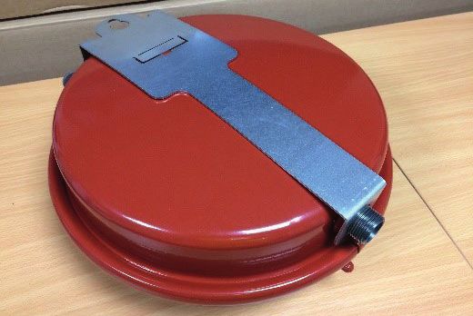
CONTENTS

1     INTRODUCTION                                 4    9    FLUE SYSTEM AND AIR SUPPLY                     30
      1.1    How a condensing boiler operates      4         9.1    Air supply                              30
      1.2    Boiler description                    4         9.2    Plume diverter kit                      30
      1.3    Flue options                          4         9.3    Conventional flue systems               31
      1.4    Boiler components                     5         9.4    External vertical conventional flue
                                                                    (Green System)                          31
2     TECHNICAL DATA                               6         9.5    External horizontal conventional flue
      2.1    Boiler technical data                 6                (Green System)                          33
      2.2    Sealed system data                    6         9.6    Flue clearances                         34
      2.3    Burner settings                       7
      2.4    Flue gas analysis                     7    10   COMMISSIONING                                  36
      2.5    Water connections                     7         10.1   Before switching on                     37
      2.6    Boiler dimensions                     8         10.2   Burner settings:
                                                                    RDB 2.2 BX burners                      37
3     OIL STORAGE AND SUPPLY SYSTEM                10        10.3   Burner settings:
      3.1    Fuel supply                           10               RDB 3.2 burners                         39
      3.2    Burner oil connection                 12        10.4   Air adjuster disc:
                                                                    15/21 and 15/26 models only             40
4     INSTALLATION                                 14        10.5   Switching on                            40
      4.1    Introduction                          14        10.6   Running the boiler                      41
      4.2    Boiler location                       14        10.7   Balancing the system                    41
      4.3    Regulations compliance                14        10.8   Completion                              41
      4.4    Heating system design                           10.9   Information for the user                41
             considerations                        14
      4.5    Pipework materials                    15   11   SERVICING                                      42
      4.6    Connections                           15        11.1   Checks before servicing                 42
      4.7    Preparation for installation          15        11.2   Dismantling prior to servicing          42
      4.8    Installing the boiler                 16        11.3   Cleaning the boiler                     42
      4.9    Filling the heating system            16        11.4   Cleaning the burner:
      4.10   Before you commission                 16               RDB 2.2 BX burners                      44
      4.11   Completion                            16        11.5   Cleaning the burner:
                                                                    RDB 3.2 burners                         45
5     PIPE CONNECTIONS                             17        11.6   Cleaning the burner - all models        45
      5.1    Water connections                     17        11.7   Air adjuster disc:
      5.2    Water connections and                                  15/21 and 15/26 models only             45
             thermostat phial positions            17        11.8   Recommissioning                         45
                                                             11.9   Burner components                       46
6     CONDENSATE DISPOSAL                          18
      6.1    General requirements                  18   12   FAULT FINDING                                  48
      6.2    Connections                           18        12.1   Boiler fault finding                    48
      6.3    Pipework                              18        12.2   Burner fault finding - Riello burners   49
      6.4    External pipework                     18
      6.5    Condensate soakaway                   19   13   SPARE PARTS                                    50
      6.6    Condensate trap                       19        13.1   Boiler parts list                       50
      6.7    Condensate disposal pipework          20        13.2   Sealed system parts list                50
      6.8    Inspection and cleaning of trap       20        13.3   Riello RDB 2.2 BX burners               51
                                                             13.4   Riello RDB 3.2 burners                  54
7     SEALED SYSTEMS                               21
      7.1    Sealed system requirements            21   14   DECLARATION OF CONFORMITY                      56
      7.2    Filling the sealed system             22
      7.3    Venting the pump                      22   15   HEALTH AND SAFETY INFORMATION                  57
      7.4    Pressure relief (safety) valve                  15.1   Insulation materials                    57
             operation                             22        15.2   Sealant and adhesive                    57
      7.5    15/21 sealed system kit               22        15.3   Kerosene and Gas Oil fuels              57
      7.6    21/26 sealed system kit               24
      7.7    26/36 & 36/46 sealed system kit       25   16   END OF LIFE INFORMATION                        58

8     ELECTRICAL                                   26   17   PRODUCT FICHE                                  59
      8.1    General                               26
      8.2    Connecting the power supply           26   18   GUARANTEE                                      60
      8.3    Frost Protection                      27   A1   WILO YONOS PARA RS RKC
      8.4    Control system wiring diagram         28        CIRCULATING PUMP                               62
      8.5    Boiler control panel wiring diagram   29
                                                        A2   WILO-PARA 25-130/7-50/SC-6#GRA
                                                             CIRCULATING PUMP                               64

Contents                                                                                                    Page 3
1        INTRODUCTION

1.1       HOW A CONDENSING BOILER OPERATES                              1.3       FLUE OPTIONS
During the combustion process, hydrogen and oxygen combine              Grant Vortex Module boilers are supplied with a low level
to produce heat and water vapour. The water vapour produced             discharge flue system, which can either be fitted to the rear, left
is in the form of superheated steam in the heat exchanger. This         hand or right hand flue outlet position, as required.
superheated steam contains sensible heat (available heat) and           It is possible to discharge the products of combustion at a higher
latent heat (heat locked up in the flue gas). A conventional boiler     level by using the following components from the Grant ‘Green’
cannot recover any of the latent heat and this energy is lost to the    flue system:
atmosphere through the flue.
                                                                        •      External module starter (available as a straight section or
The Grant Vortex condensing boiler contains an extra heat                      with a 90° elbow, enabling the installer to use any flue outlet
exchanger which is designed to recover the latent heat normally                from the boiler casing)
lost by a conventional boiler. It does this by cooling the flue gases
to below 90°C, thus extracting more sensible heat and some of           •      Fixed extensions 150mm, 250mm, 450mm and 950mm
the latent heat. This is achieved by cooling the flue gases to their    •      Adjustable extension 195 to 270mm
dew point (approximately 55°C).                                         •      45° elbow
To ensure maximum efficiency, the boiler return temperature               •      High level 90° or vertical terminal
should be 55°C or less, this will enable the latent heat to be
                                                                        It is possible to extend the flue system by 19m vertically (from the
condensed out of the flue gases.
                                                                        boiler outlet) using this system.
•      The boiler will achieve net thermal efficiencies of 100%.
                                                                        Should the flue system need to navigate around objects, the
To achieve maximum performance from the Grant Vortex boiler,            green system can be used to horizontally extend the flue system
it is recommended that the heating system is designed so that a         by up to 3m from the centre of the boiler outlet.
temperature differential of 20°C between the flow and return is
                                                                        Please note, the flue may either be brought up vertically from the
maintained.
                                                                        boiler, or horizontally. Not a combination of the two.
The Grant Vortex boiler will however still operate at extremely
                                                                        Alternatively, the plume diverter kit, available from Grant, can be
high efficiencies even when it is not in condensing mode and
                                                                        used to vertically extend the flue system.
therefore is suitable for fitting to an existing heating system
without alteration to the radiator sizes. The boiler is capable of a    Please see Sections 4.7 and 9 for more detailed instructions on
maximum flow temperature of 75°C.                                       how to install the flue system.

1.2       BOILER DESCRIPTION                                            Conventional flues only may be fitted to Grant Vortex Module
Grant Vortex Module modules have an insulated weatherproof              boilers.
enclosure made of galvanised steel and are designed for external
installation, either against a wall or free standing some distance
away from the property, as required.                                                           ! NOTE !
The Grant Vortex module range of automatic pressure jet oil
boilers have been designed for use with a fully pumped central           The flue system materials and construction MUST be
heating system with indirect domestic hot water cylinder.                suitable for use with oil-fired condensing boilers. Failure
                                                                         to fit a suitable conventional flue may invalidate the
They are not suitable for use with either a direct cylinder or a
‘primatic’ cylinder or gravity hot water.                                guarantee on the boiler.
The boilers are suitable for use on open vented or sealed central
heating systems. Sealed system conversion kits are available with
the necessary components. Refer to Section 7.
All boilers are supplied with the control panel and burner factory
fitted.
All the models in the current Grant Vortex range of boilers are
designed to comply with the maximum NOx emissions under the
Energy-related Products Directive (ErP).
* From the 26th September 2018, the maximum NOx emissions
for all new oil fired boilers (up to and including 400kW for both
new build and replacement boiler installations) is 120mg/kWh.

Page 4                                                                                                         Section 1: Introduction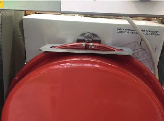
1.4 BOILER COMPONENTS
All burners are pre-set for use with kerosene and are supplied
ready to connect to a single pipe fuel supply system with a loose
! NOTE !
flexible fuel line and 3/8ʺ to 1/4ʺ BSP male adaptor supplied with If the ON/OFF switch is set to off the boiler will NOT supply
the boiler. central heating or heat domestic hot water (if a hot water
If required, an additional flexible fuel line (900 mm in length, cylinder is connected to the boiler). The built-in frost
product code: 20022601 or 600mm in length, product code: thermostat will also not operate.
RBS36XS) and 3/8” to 1/4” BSP male adaptor (product code:
Z3003602) are available to purchase from Grant, for two-pipe oil Service/Test Switch
supply systems. A service switch is fitted to the control panel to allow the Service
The temperature of the water leaving the boiler to heat the Engineer to test-fire the boiler.
radiators and hot water cylinder is user adjustable. Heating Thermostat
The boiler is fitted with an overheat thermostat (which allows This control allows the temperature of the water leaving the boiler
it to be used on a sealed central heating system) which will to heat the radiators (and domestic hot water) to be adjusted. This
automatically switch off the boiler if the heat exchanger exceeds a will be set by the installer to the optimum temperature for efficient
pre-set temperature of 110°C ± 3°C. operation of the boiler. It should be left set in this position.
The control panel is fitted with an ON/OFF switch, service switch, Overheat Thermostat (Overheat Reset)
boiler thermostat control knob and the manual reset button for the The boiler is fitted with a safety overheat thermostat which
overheat thermostat. will automatically switch off the boiler in the case of a control
malfunction causing overheating.
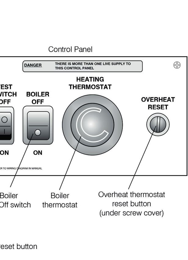
Figure 1-1 shows the position and details of the control panel for
the Vortex Module boiler.
1.4.1 BOILER CONTROLS
To access the control panel, remove the front casing door from
the boiler. The controls on the panel are as follows:
Boiler On/Off switch
This switches the boiler on and off. The boiler ON/OFF switch
incorporates a ‘mains on’ neon which lights when the boiler is
switched on. Please note that the ‘mains on’ neon does not
necessarily indicate that the burner is firing.
Figure 1-1: Vortex Module boiler control panel and reset button
Section 1: Introduction Page 5
2            TECHNICAL DATA

2.1       BOILER TECHNICAL DATA
Table 2-1: Boiler technical data
                                                                                        Module                                                          Module
                                             Units
                                                             15/21             15/26              26/36                  36/46                 46/58              58/70
                                              litre           16.5               19                  21                   21                     50                50
Water content
                                              gal              3.6               4.2                 4.7                  4.7                    11                11
                                               kg             109               143                  162                  162                   274               288
Weight (dry)
                                               lb             240               315                  357                  357                   604               635
                                              kW               21                26                  36                   46                     58                70
Maximum heat output (Kerosene)
                                             Btu/h           71,700            88,700            122,800                157,000               197,900            238,800
Minimum flow rate (∆T=10°C)                    l/h           1,800             2,200              3,000                  4,000                 5,200              6.000
Minimum flow rate (∆T=20°C)                    l/h            900              1,100              1,500                  2,000                 2,600              3,000
Condensate connection                                                                       22 mm (only connect plastic pipe)
Flue diameter                                         15/21 & 15/26 =80mm                                    26/36, 36/46, 46/58, 58/70kW = 100mm
Waterside resistance ∆T=10°C                 mbar                      28.5                                                         26.0
Waterside resistance ∆T=20°C                 mbar                      10.0                                                         9.5
Maximum static head                            m                                                                28
Minimum circulating head                       m                                                                1
Boiler thermostat range                        °C                                                            50 to 75
Limit (safety) thermostat shut off
                                               °C                                                            110 ± 3
temperature
Maximum hearth temperature                     °C                                                          Less than 50
Electricity supply                                                                               ~230 1ph 50Hz 5A fused
Burner motor power                           Watts                                         90                                                            150
Absorbed motor power                          kW                                                               0.15
Starting current                             Amps                                         4.2                                                            6.4
Running current                              Amps                                         0.85                                                           1.2
Oil connection                                                                          ¼ʺ BSP male (on end of flexible fuel hose)
                                             mbar                                           Minimum: 0.087 - Maximum: 0.37
Conventional flue draught
                                             in wg                                          Minimum: 0.035 - Maximum: 0.15
Maximum operating pressure -
                                              bar                                                              2.0
sealed/open system
Maximum operating pressure -
                                              bar                                                              3.0
pressure relief valve
Boiler type                                                                                                  ON/OFF

2.2       SEALED SYSTEM DATA
Table 2-2: Sealed System Data
                                                                                                           15/21, 15/26, 26/36 and 36/46
Heating system pressure (cold)                                                                    Maximum 1.0 bar           |      Minimum 0.5 bar
Operating pressure of pressure relief valve                                                                              3.0 bar
Expansion vessel size (pre-charged at 1 bar)                                     10 litres (15/21)     |     12 litres (15/26)      |       16 litres (26/36 and 36/46)
Maximum heating system volume (including boiler)*                              104 litres (15/21)     |      125 litres (15/26)         |   171 litres (26/36 & 36/46)**
Cold water mains connection                                                                                      15 mm copper pipe
Pressure relief valve discharge connection                                                                       15 mm copper pipe
* Based on vessel charge of 0.3 bar and system cold fill pressure of 0.5 bar. These values are the remaining system volume available after deducting the boiler
  water content.
** Approximately

Page 6                                                                                                                             Section 2: Technical Data
2.3        BURNER SETTINGS
 Table 2-3: Burner settings

     Boiler         Heat output                                                           Burner                                                          Flue
                                                         Oil                 Burner                                  Fuel       Flue gas
    models                                                         Smoke                   head/     Distance                                CO2          gas
                                         Nozzle       pressure                head                                flow rate      temp.
    (burner       (kW)     (Btu/h)                                  No.                   air disc   D ¹⁰ (mm)                               (%)         VFR ‡
                                                        (bar)                 type                                  (kg/h)        (°C)
     type)                                                                                setting                                                        (m³/hr)
   Outdoor        15.0      51,200     0.45/80°EH        7.5        0-1      BX 500       Disc: B       11           1.31       65 - 70      12.5         16.0
 Module 15/21
    (Riello       18.0     63,400      0.55/60°ES        7.0        0-1      BX 500       Disc: C      11.5          1.58       70 - 75      12.5         20.0
  RDB2.2 BX
   E15/21)        21.0 *    71,600     0.60/60°ES        8.0        0-1      BX 500       Disc: C       13           1.84       75 - 80      12.5         23.0

  Outdoor         15.0      51,200     0.45/80°EH        8.0        0-1      BX 500       Disc: B      11.5          1.25       60 - 65      12.5         16.0
 Module 15/26
   (Riello        21.0 *    71,600     0.60/60°ES        8.0        0-1      BX 500       Disc: C       13           1.75       65 - 70      12.5         23.0
 RDB2.2 BX
   V15/26)        26.0     88,700      0.75/60°ES        8.5        0-1      BX 500           N/A       15           2.16       75 - 80      12.5         28.5

   Outdoor        26.0     88,700      0.75/60°ES        8.0        0-1      BX 700           N/A       15           2.16       65 - 70      12.5         28.5
 Module 26/36
    (Riello       31.0 *   105,700     0.85/60°ES        9.0        0-1      BX 700           N/A       16           2.58       70 - 75      12.5         34.5
  RDB2.2 BX
   V26/36)        36.0     122,800     1.00/60°ES        9.0        0-1      BX 700           N/A      17.5          2.99       75 - 80      12.5         39.5

   Outdoor        36.0     122,800     1.00/60°ES        9.0        0-1      BX 700           N/A      17.5          3.09       75 - 80      12.5         39.5
 Module 36/46
    (Riello       41.0 *   140,000     1.10/60°ES        10.0       0-1      BX 700           N/A      17.5          3.52       80 - 85      12.5         45.5
  RDB2.2 BX
   V36/46)        46.0     157,000      1.25/60°S        8.0        0-1      BX 700           N/A       20           3.95       85 - 90      12.5         51.0

 External 46/58   46.0     157,000      1.25/80°S        8.0        0-1        GIB        Head: 0        -           3.92       75 - 80      12.5         51.0
    (Riello
                  52.0 *   177,500      1.35/80°S        9.5        0-1        GIB        Head: 0        -           4.43       75 - 80      12.5         58.5
    RDB3.2
   VORT 58)       58.0     197,900      1.65/80°S        8.0        0-1        GIB        Head: 0        -           4.94       75 - 80      12.5         66.0
 External 58/70   58.0     197,900      1.35 45°H        10.0       0-1        GIB        Head: 0        -           4.97       75 - 80      12.5         66.0
    (Riello
                  64.0 *   218,300      1.50 45°H        10.5       0-1        GIB        Head: 2        -           5.49       75 - 80      12.5         72.5
    RDB3.2
   VORT 70)       70.0     238,800      2.00 45°S        8.5        0-1        GIB        Head: 2        -           6.00       75 - 80      12.5         78.5
 Notes:
 ‡    Flue gas VFR: Flue gas volumetric flow rate
 1.   The data given above is approximate only and is based on the boiler being used with a low level balanced flue.
 2.   The above settings may have to be adjusted on site for the correct operation of the burner.
 3.   Gas Oil is NOT suitable for use with Grant Vortex boiler range
 4.   The flue gas temperatures given above are ± 10%.
 5.   When commissioning, the air damper must be adjusted to obtain the correct CO2 level.
 6.   * Factory settings: 15/21 - 21kW, 15/26 - 21kW, 26/36 - 31kW, 36/46 - 41kW, 46/58 - 52kW, 58/70 - 64kW.
 7.   The combustion door test point may be used for CO2 and smoke readings only. Do not use this test point for temperature or efficiency readings.
 8.   When setting the 15/21 and 15/26 to 15kW, the air adjuster disc requires repositioning. Refer to Section 10.4 (air adjuster disc).
      When setting the 15/26 to 26kW, the air adjuster disc is not required. Refer to Section 10.4 (air adjuster disc).
      When setting the 58/70 to 58kW, the combustion head must be changed. Refer to Section 10.3 (Burner Settings: RDB3.2 Burners)
 9.   The installer must amend the boiler data label if the output is changed.
 10. Refer to Section 10.2 for information on how to set Distance D (Figure 10-5).

2.4        FLUE GAS ANALYSIS
To allow the boiler to be commissioned and serviced, the boiler is supplied with a combustion test point on the front cleaning door.
When this test point is used please note the following:
•    The test point is for CO2 and smoke readings only.
•    The boiler efficiency and temperature must be taken from the flue test point on high level, vertical and conventional flue adaptors.
•    Concentric low level flues do not contain a test point. The temperature and efficiency readings must be taken from the flue terminal.

2.5        WATER CONNECTIONS
 Table 2-4: Water connections
                                                         Flow connection                                              Return connection
          Boiler model
                                            Size                Fitting           Supplied                Size                Fitting           Supplied
                                                            Compression
      Outdoor Module 15/21              22 mm pipe                               In fittings kit      22 mm pipe            Compression              Fitted
                                                              straight
                                                            Compression
      Outdoor Module 15/26              22 mm pipe                               In fittings kit      22 mm pipe            Compression              Fitted
                                                              elbow
                                                            Compression
      Outdoor Module 26/36              28 mm pipe                               In fittings kit      28 mm pipe            Compression              Fitted
                                                              straight
                                                            Compression
      Outdoor Module 36/46              28 mm pipe                               In fittings kit      28 mm pipe            Compression              Fitted
                                                              straight
          External 46/58                 1¼ʺ BSP           Female socket             Fitted            1¼ʺ BSP           Female socket               Fitted
          External 58/70                 1¼ʺ BSP           Female socket             Fitted            1¼ʺ BSP           Female socket               Fitted

Section 2: Technical Data                                                                                                                               Page 7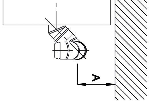
2.6      BOILER DIMENSIONS
                                                                  946

                                                 104

                                                                  6
                                                          ø7

                                  120 120
                      384

                                                           PLAN VIEW
                                  72

                                                                             487                                   736

                                                                          ø 110
                                    120

                                                                                                                                         880
                                                                  ø 50
                                    210

                                                                                       813
                                    120
                                    187

                                             102
      REAR VIEW                                          LEFT SIDE VIEW                                           RIGHT SIDE VIEW

Figure 2-1: 15/21 External module dimensions

                                                              1006
                                             104
                            71

                                                              6
                            180

                                                         ø7
                     505

                            180

                                                           PLAN VIEW

                                                                                 528                              796

                                                                         ø 110
                            97

                                                              ø 50
                                                                                             26-36 & 36-46 =824
                            242

                                                                                                 15-26 =816

                                                                                                                                         910
                            239
                            179

        END VIEW
                                            50           LEFT SIDE VIEW                                           RIGHT SIDE VIEW

                                                   117

Figure 2-2: 15/26, 26/36 and 36/46 External module dimensions

Page 8                                                                                                             Section 2: Technical Data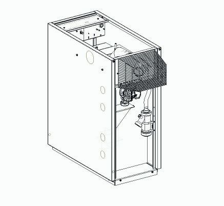
1157
                                   70

                                                 76

                             191
                                             ø

                       586

                             191
                             102
                                                      PLAN VIEW

                                                                   713          947

                                                         ø 110
                             184

                                              ø 50

                                                                                                     1239
                             398

                                                                         1140
                             239
                             179

       REAR VIEW                    50            LEFT SIDE VIEW                RIGHT SIDE VIEW

Figure 2-3: 46/58 and 58/70 External module dimensions

Section 2: Technical Data                                                                         Page 9
3         OIL STORAGE AND SUPPLY SYSTEM

3.1       FUEL SUPPLY                                                      The fire valve must have an operating temperature of between
3.1.1     FUEL STORAGE                                                     90 and 95°C to avoid unnecessary nuisance shut-offs to the oil
The tank should be positioned in accordance with the                       supply.
recommendations given in BS 5410-1 (Code of practice for                   A flexible fuel hose and ¼ʺ isolating valve are supplied loose with
liquid fuel firing. Installations for space heating and hot water          the boiler, to make the final connection to the burner.
supply purposes for domestic buildings). This gives details of the         If a two-pipe system or deaerator is to be used, the following
requirements for suitable oil tank construction, tank installation,        additional items will be required:
tank bases, fire protection and secondary containment.                     •     Flexible fuel hose ⅜ʺ male x ¼ʺ female (product code:
For installations of greater than 70kW output capacity, the tank                 RBS36 - 900 mm / product code: RBS36XS - 600mm)
should be installed accordance with BS 5410-2.                             •     ⅜ʺ x ¼ʺ BSP adaptor (product code: Z3003602)
Oil storage tanks should comply with the following standards:              •     ¼ʺ isolating valve (product code: ISOLATION1/4)
•     Plastic tanks OFT T100                                               These are available to purchase from Grant.
•     Steel tanks OFT T200                                                 Metal braided flexible fuel hoses should be replaced ANNUALLY
                                                                           when the boiler is serviced.

                   ! CAUTION !                                             Long life flexible fuel hoses should be inspected annually and
                                                                           replaced, if necessary, or after a maximum five years service life.
                                                                           Flexible fuel hoses MUST NOT be used outside of the appliance
 A galvanised tank must not be used.                                       casing.

                                                                           3.1.3     SINGLE PIPE (GRAVITY) SYSTEM -
                        ! NOTE !                                                     (REFER TO FIGURE 3-1)
 Plastic tanks should be stood on a firm non-combustible                                                       Maximum pipe run (m)
                                                                                 Head A (m)
 base that adequately and uniformly supports the weight of                                            10 mm OD pipe           12 mm OD pipe
 the tank over its entire base area.
                                                                                     0.5                     10                      20
The tank capacity should be selected to suit the appliance rated
                                                                                     1.0                     20                      40
output. Refer to BS5410-1 for guidance.
                                                                                     1.5                     40                      80

3.1.2     FUEL PIPES                                                                 2.0                     60                     100
Fuel supply pipes should be either copper or steel. Galvanised             If the storage tank outlet is at least 300 mm above the level of the
pipes or fittings should not be used.                                      burner oil pump, a single pipe (gravity) system should be used.
Plastic oil supply pipe conforming to BS EN 14125 can be used              The maximum height of the oil level above the burner oil pump
for underground pipe runs, but must not be used above ground.              when the tank is full, must not exceed four metres. If this height
                                                                           is exceeded, a pressure reducing valve must be fitted in the oil
All soft copper pipe connections should preferably be made using           supply pipe between the tank and the burner oil pump.
flared fittings. If compression fittings are to be used, a suitable
pipe insert must be fitted into the pipe end.                              The maximum length of pipe run from the tank to the burner is
                                                                           limited by the minimum head of oil (the height of the tank outlet
Soft soldered connections must NOT be used on oil supply                   above the burner oil pump).
pipework.
Fuel supply pipework should be of a suitable diameter, depending
on the type of oil supply system being used. Refer to information          3.1.4     TWO PIPE SYSTEM -
given in sections 3.1.3, 3.1.4 or 3.1.5.                                             (REFER TO FIGURE 3-2)
Run pipes as level as possible to prevent air being trapped. Take                                              Maximum pipe run (m)
the most direct route possible from tank to burner whilst locating               Head A (m)
the pipe where it will be protected from damage.                                                      10 mm OD pipe           12 mm OD pipe
Pipes should be supported to prevent sagging and sleeved where                        0                      35                     100
they pass through a wall.                                                            0.5                     30                     100
A metal body fuel filter with a filtration size of no more than 50 μm
                                                                                     1.0                     25                     100
(micron) must be fitted in the oil supply pipe close to the tank. This
should be fitted with sufficient clearance around and below it to                      1.5                     20                      90
allow easy access for maintenance.
                                                                                     2.0                     15                      70
An isolating valve should also be fitted at the tank, before the filter,
                                                                                     3.0                      8                      30
to allow the oil supply to be shut off for the filter to be serviced.
A second filter (15 μm for Kerosene) must be located closer to the                   3.5                      6                      20
burner to protect the burner pump and nozzle from contamination.           If the storage tank outlet is below the level of the burner oil pump,
Refer to Figures 3-1 to 3-3.                                               a two pipe (sub gravity) system can be used.
A remote sensing fire valve must be installed in the fuel supply           The return pipe should be at the same level as the tank outlet,
line in accordance with BS5410-1.                                          between 75 to 100 mm above the base of the tank. The return
A fusible wheelhead type combined isolating/fire valve MUST                pipe should be a sufficient distance from the tank outlet so as to
NOT be used in place of a remote sensing fire valve.                       prevent any sediment disturbed by the return entering the supply
                                                                           pipe from the tank.
The fire valve must be located externally to the appliance casing,
with the fire valve sensor located above the burner.                       A non-return valve should be fitted in the supply pipe, along with
                                                                           a fire valve and filters (refer to section 3.1.2 - fuel pipes). A non-
A spring clip for mounting the sensor is supplied fitted to the            return valve should also be fitted in the return pipe if the top of the
boiler, on the rear of the control panel.                                  tank is above the burner oil pump.
The fire valve should be located after the second (15 micron) filter,      The maximum suction height (from the tank outlet to the level of
i.e. between the filter and the point at which the oil line enters the     the burner oil pump), must not exceed 3.5 metres.
appliance casing. Refer to Figures 3-1 to 3-3.
                                                                           The pump vacuum should not exceed 0.4 bar. Beyond this limit,
                                                                           gas is released from the oil.

Page 10                                                                                    Section 3: Oil Storage and Supply System
4m Max
6
8
3 2 1
11 4 2
5
300mm
7
Min
Figure 3-1: Single pipe (gravity) system
6
8 9
11 4 2
5
7
3.5m Max
150mm
9 3 2 1
Figure 3-2: Two pipe system
6 10
8
3.5m Max
11 4 2
5
9 3 2 1
7
Figure 3-3: De-aeration device system
Key to oil supply diagrams
1 Oil tank 5 Oil filter (15μm max. filtration size) 9 Non-return valve
2 Isolating valve 6 Fire valve sensor 10 De-aerator*
3 Oil strainer 7 Oil pump 11 Appliance isolation valves
4 Fire valve to BS5410-1 8 Burner
* Position of de-aeration device must be level with or above the oil pump
Section 3: Oil Storage and Supply System Page 11For guidance on the installation of top outlet fuel tanks and 3.2 BURNER OIL CONNECTION
suction oil supply pipe sizing, refer to OFTEC Technical Book 3:
Storage and Supply, available for purchase from OFTEC.
If a two-pipe system is to be used, the following additional items
will be required:
! WARNING !
• Flexible fuel hose ⅜ʺ male x ¼ʺ female (product code: The blanking plug supplied in the inlet (suction) port is
RBS36 - 900 mm / product code: RBS36XS - 600mm) plastic and will not provide an oil tight seal when the pump
• ⅜ʺ x ¼ʺ BSP adaptor (product code: Z3003602) is running.
• ¼ʺ isolating valve (product code: ISOLATION1/4) Ensure that the supply from the tank is connected to this
These are available to purchase from Grant. port and that the plastic plug is discarded.
The burner fuel pump is supplied factory set for use with a single
3.1.5 SINGLE PIPE (SUCTION) SYSTEM WITH pipe (gravity) oil supply system.
DEAERATOR - (REFER TO FIGURE 3-3) For ease of access to the burner oil pump connections, the burner
If the storage tank outlet is below the level of the burner oil pump, should be removed from the boiler as follows:
an alternative to the two pipe (sub gravity) system is the single
pipe (suction) system using a deaerator, e.g. a ‘Tiger Loop’ 1. Remove the red plastic burner cover.
device. • 15/21, 21/26, 26/35 and 36/46 models:
The deaerator creates a loop with the burner oil pump, with the oil Unscrew and remove the TWO fixing screws from the
being circulated through the pump out to the deaerator and back red burner cover and remove the cover from the burner.
to the pump. Any air in the single pipe lift from the tank is removed • 46/58 and 58/70 models:
from the oil, collected in the deaerator and then discharged to
Unscrew and remove the THREE fixing screws from the
outside.
red burner cover and remove the cover from the burner.
2. Unscrew and remove the single burner fixing nut from the
! WARNING ! stud on the burner flange (at the top of the burner) using a 13
mm spanner. Retain the fixing nut for re-fitting the burner.
To prevent any fuel vapour being discharged within 3. Carefully withdraw the burner from the boiler.
the building, the deaerator must be fitted outside, in
accordance with BS 5410-1, unless it is specifically
designed to be installed inside.
The de-aerator must be mounted vertically at the same level as
(or above) the burner oil pump. Refer to Figure 3-3.
RETURN Tiger Loop
FROM PUMP
SUPPLY 1/4" BSP female
TO PUMP connections
SUPPLY
FROM TANK
Figure 3-4: Tiger loop de-aeration device
An external deaerator must not be fitted within 500 mm of a flue
terminal.
Always follow the manufacturers installation instructions supplied
with the deaerator.
To use a de-aertor, the following additional items will be required:
• Flexible fuel hose ⅜ʺ male x ¼ʺ female (product code:
RBS36 - 900 mm / product code: RBS36XS - 600mm)
• ⅜ʺ x ¼ʺ BSP adaptor (product code: Z3003602)
• ¼ʺ isolating valve (product code: ISOLATION1/4)
These are available to purchase from Grant.
Page 12 Section 3: Oil Storage and Supply System3.2.1 SINGLE PIPE (GRAVITY) CONNECTION - 3.2.2 TWO PIPE CONNECTION
REFER TO FIGURE 3-5 For either a two pipe (sub gravity) or a single pipe (suction)
Connect the oil supply to the burner oil pump as follows: system with a deaerator, the following additional items will be
required:
1. Unscrew and remove the plastic blanking plug from the
suction port of the burner oil pump and discard it. • Flexible fuel hose ⅜ʺ male x ¼ʺ female (product code:
RBS36 - 900 mm / product code: RBS36XS - 600mm)
2. Fit the nut of the elbow connection on the flexible fuel hose
(supplied with the boiler) into the suction port and tighten. • ⅜ʺ x ¼ʺ BSP adaptor (product code: Z3003602)
3. Fit the ¼ʺ isolating valve (not supplied with the boiler) to the • ¼ʺ isolating valve (product code: ISOLATION1/4)
end of the rigid oil supply pipe using a fitting to suit the pipe These are available to purchase from Grant.
size and type (not supplied). Connect the oil supply to the burner oil pump as follows:
4. Connect the other end of the flexible fuel hose to the isolating 1. Fit the flexible fuel hose (supplied with the boiler) to the
valve using the ⅜ʺ x ¼ʺ BSP adaptor (supplied with the suction port of the burner oil pump, as detailed in Section
boiler). 3.2.1.
5. Re-fit the burner to the boiler. With either a two pipe (sub gravity) system or a single pipe
(suction) system with a deaerator, the by-pass screw (supplied
7 with the boiler) must be fitted to the burner oil pump as follows:
1. Unscrew and remove the blanking plug from the return port
on the burner oil pump and discard it.
2. Fit the by-pass screw into the threaded hole (inside the return
port) and fully screw it in using an Allen key.
3. Fit the nut of the elbow connection on the flexible fuel hose
5 into the return port and tighten.
4. Fit the ¼ʺ isolating valve (not supplied) to the end of the rigid
oil return pipe (to the deaerator or oil tank) using a fitting to
suit the pipe size and type (not supplied).
8 5. Connect the other end of the flexible fuel hose (not supplied)
4 to the isolating valve using a ⅜ʺ x ¼ʺ BSP adaptor (not
supplied).
6. Re-fit the burner to the boiler.
3
1 6 2
Figure 3-5: Riello oil pump
Item Description
1 Inlet (suction) port
2 Return port
3 By-pass screw
4 Pressure gauge port
5 Pressure adjustment
6 Vacuum gauge port
7 Solenoid
8 Auxiliary pressure test point
Section 3: Oil Storage and Supply System Page 134 INSTALLATION
4.1 INTRODUCTION • BS 7593 (Code of Practice for treatment of water in domestic
The boiler is supplied already fully assembled, with the flue hot water central heating systems)
terminal guard loose inside the boiler. The installation procedure • BS 7671 (Requirements for Electrical installations, IET Wiring
therefore begins with unpacking of the packed boiler. Regulations)
• BS 7291 (Thermoplastics pipe and fitting systems for hot and
cold water for domestic purposes and heating installations in
4.2 BOILER LOCATION buildings. General requirements)
The External module must stand on a firm and level surface • BS 7074-1 (Application, selection and installation of
capable of supporting the boiler when full of water. Refer to expansion vessels and ancillary equipment for sealed water
Section 2.1 for weights. systems. Code of practice for domestic heating and hot water
It does not require a special hearth as the temperature of the supply)
boiler base is less than 50°C. • BS 2869 (Fuel oils for agricultural, domestic and industrial
The module can be installed either against the building, or ‘free engines and boilers. Specification)
standing’ some distance away from the building.
Sufficient clearance must be allowed at the front of the boiler to
remove the burner and baffles for servicing, clearance must also
! WARNING !
be left at the top of the module to allow removal of the top panel.
BS5410-1: 2019 requires that appliances located in a
Adequate clearance is also required at the rear of the module, building or structure or within a restricted area externally
to allow removal of the back panel for access to the condensate should have a CO detector conforming to BS EN 50291-1
trap. installed in the same room/space.
4.3 REGULATIONS COMPLIANCE
4.4 HEATING SYSTEM DESIGN
! NOTE ! CONSIDERATIONS
Failure to install and commission appliances correctly may
invalidate the boiler guarantee.
! WARNING !
Before starting any work on the boiler or fuel supply,
Installation of a Grant Vortex boiler must be in accordance with please read the Health and Safety information given in
the following recommendations: Section 15.
• Building Regulations for the Republic of Ireland and Northern
Ireland and any local Byelaws which you must check with the To achieve the maximum efficiency possible from the Grant Vortex
local authority for the area. boiler, the heating system should be designed to the following
• Model and local Water Undertaking Byelaws. parameters:
• Applicable Control of Pollution Regulations. RADIATORS:
• National Building Regulations and any local Byelaws. • Flow temperature 70°C
• Model Byelaws and the Water Supply Regulations. • Return temperature 50°C
• The following OFTEC requirements:
• Differential 20°C
• OFS T100 Polythene oil storage tanks for distillate fuels.
Size radiators with a mean water temperature of 60°C.
• OFS T200 Fuel oil storage tanks and tank bunds for use
with distillate fuels, lubrication oils and waste oils. Design system controls with programmable room thermostats
Further information may be obtained from the or use weather compensating controls to maintain return
OFTEC Technical Book 3 (Installation requirements temperatures below 55°C.
for oil storage tanks) and OFTEC Technical Book 4
(Installation requirements for oil fired boilers).
The installation should also be in accordance with the latest ! NOTE !
edition of the following Irish and UK Standard Codes of Practice
(and any relevant amendments): The boiler should not be allowed to operate with return
• BS 5410-1: 2019 (Code of practice for liquid fuel firing. temperatures of less than 40°C when the system is up to
Installations for space heating and hot water supply purposes temperature.
for domestic buildings) The use of a pipe thermostat is recommended to control the return
• This standard covers domestic installations up to 70kW. temperature when using weather compensating controls.
• BS 5410-2: 2018 (Code of practice for liquid fuel firing. Non-
domestic installations) UNDERFLOOR:
• This standard should be followed with regard to • Flow temperature 50°C
installations with an output capacity in excess of 70kW. • Return temperature 40°C
• Where the combined outputs of multiple appliances • Differential 10°C
located together at a domestic dwelling exceed 70kW
In underfloor systems, it is essential that the return temperature
then then a dedicated plant room as specified in BS
5410-2 is recommended. must be maintained at or above 40°C to prevent internal corrosion
of the boiler water jacket.
• BS EN 12828 (Heating systems in buildings. Design for
water-based heating systems) Refer to Section 2.5 for the size and type of the connections and
• BS EN 12831-1 (Energy performance of buildings. Method Section 5 for the position of the connections.
for calculation of the design heat load)
• BS EN 14336 (Heating systems in buildings. Installation and
commissioning of water based heating systems)
Page 14 Section 4: InstallationOPEN VENTED SYSTEMS: allow the heating system to be drained.
4.7 PREPARATION FOR INSTALLATION
! NOTE ! 1. Carefully remove the boiler and remove it from the transit
pallet.
The presence of ‘pumping over’ in an open vented heating 2. Remove the case top panel (four screws) and also the front
system connected to the Grant Vortex boiler will invalidate and rear panels as required.
the product guarantee. 3. The flue may exit the boiler from the left, right or rear of the
casing. Carefully press out the pre-cut section on the side
Open vented systems must be correctly designed and installed. or rear casing panel to provide the opening in the required
The open safety vent pipe must be positioned to prevent ‘pumping position for the flue to pass through the casing.
over’ (i.e. the discharge of water from the open safety vent pipe Fit the 15-26 cover panel (with the round flue exit hole) over
into the feed and expansion cistern under the pressure created by the chosen opening in the casing. Fit the circular rubber
the circulator). For detailed information on the correct design of sealing grommet provided into the circular hole in the cover
open vented heating systems, and the correct location of the open panel before fitting the flue terminal section (or first flue
safety vent pipe, refer to the CIBSE Domestic Heating Design extension if the flue is being extended using the green
Guide and OFTEC Technical Book 4 (Installation). system).
4. Slacken the M8 nut holding the starter elbow and rotate the
elbow to the required direction for the flue to exit the casing.
4.5 PIPEWORK MATERIALS
5. Push the end of the flue terminal section or flue extension
The Grant Vortex boiler is compatible with both copper and plastic (with the red seal) from the outside of the boiler casing
pipe. Where plastic pipe is used it must be of the oxygen barrier through the sealing grommet in the casing panel. The
type and be the correct class (to BS 7291-1) for the application terminal section has been factory lubricated. Take care not to
concerned. dislodge or damage the red flue seal.
On either sealed or open-vented systems; where plastic pipe is
used a minimum of ONE metre of copper pipe (or as per pipe
manufacturers instructions) MUST be connected between both If using the low level flue option provided with the boiler:
the boiler flow and return connections and the plastic pipe. 6. Carefully insert the terminal into the starter elbow until the
bend of the terminal contacts the outer casing, then pull the
terminal forward approximately 25mm and rotate the bend so
! NOTE ! that the outlet is horizontal.
Rear Exit - The flue must discharge away from the
building.
Do not connect plastic pipe directly to the boiler.
Side Exit - The flue should discharge towards the rear
of the casing to prevent flue gases re-entering the boiler
Grant does not accept any responsibility for any damage, casing through the air inlet vents on the casing door.
however caused, to plastic piping or fittings. The flue terminal must be fitted horizontally to prevent
dripping from the end of the terminal.
SEALED SYSTEMS
If plastic pipe is to be used, the installer must check with the
plastic pipe manufacturer that the pipe to be used is suitable for If you are planning to extend the flue before terminating:
the temperature and pressures concerned. 7. Carefully insert the first extension/elbow piece into the starter
Plastic pipe must be Class S to BS 7291-1. elbow and secure with a locking band.
! WARNING ! 8. Tighten the M8 nut holding the starter elbow and fit the
stainless steel flue guard (if using low level flue option
provided with boiler) using the two screws provided.
When plastic pipe is used, the system MUST incorporate
9. The top panel of the casing has been designed so that it
a low pressure switch to shut off power to the boiler if
may be fitted to create a slight slope away from the side
the system pressure drops below 0.2 bar. A suitable low positioned against the wall. To tilt the top panel, loosen the
pressure switch kit is available to purchase from Grant. four top panel casing screws and push down on the side
furthest from the wall. Tighten the screws. See Figure 4-1.
UNDERFLOOR PIPEWORK
Plastic pipe may be used on underfloor floor systems where the
plastic pipe is fitted after the thermostatic mixing valve. Copper
tube must be used for at least the first metre of flow and return
primary pipework between the boiler and the underfloor mixing/
blending valves.
4.6 CONNECTIONS
4.6.1 FLOW AND RETURN CONNECTIONS
Refer to Section 5.
4.6.2 CONDENSATE CONNECTION
Grant Vortex boilers are supplied with a factory-fitted condensate
trap to provide the required 75 mm water seal in the condensate
discharge pipe from the boiler.
Refer to Section 6 for details of the condensate disposal pipework.
4.6.3 DRAIN COCK
A drain cock is fitted at the bottom on the front of the boiler to
Section 4: Installation Page 154.8 INSTALLING THE BOILER 4.10 BEFORE YOU COMMISSION
1. If the boiler is to be fitted against a wall, prepare the wall to To avoid the danger of dirt and foreign matter entering the boiler
accept the heating system pipework. To mark the wall for the complete heating system should be thoroughly flushed
drilling, refer to Section 2.6 for the positions of the pipework out – both before the boiler is connected and then again after
openings in the enclosure sides. the system has been heated and is still hot. This is especially
important where the boiler is to be installed on an older system.
For optimum performance after installation, the boiler and the
! NOTE ! associated heating system must be flushed in accordance with
the guidelines given in BS 7593 (Treatment of water in domestic
Pipework should be insulated where it passes through the hot water central heating systems). This must involve the use
of a proprietary cleaner, such as Sentinel X300 (new systems),
wall into the boiler enclosure.
Sentinel X400 (existing systems), or Fernox Restorer.
If the boiler is to be installed ‘free standing’ (i.e. away from After cleaning, it is vitally important that all traces of the cleaner
a wall) and the pipework run underground, push out the are thoroughly flushed from the system.
‘knock-outs’ to open the required pipe openings in the base
of the boiler enclosure. Using a sharp knife, cut through the For long term protection against corrosion and scale, after
polystyrene in the base, around the edge of the holes, to cleaning/flushing a suitable inhibitor should be added to the
allow the flow and return pipes to enter the enclosure. system water, such as Grant G1000, Sentinel X100 or Fernox
MB-1, in accordance with the manufacturers’ instructions.
2. The electrical supply to the boiler should be routed through
the wall in a suitable conduit, such that it enters the boiler Failure to follow the above will invalidate the guarantee.
enclosure via one of the unused pipework openings. The If the boiler is installed in a garage, out house or outside, in order
cable can be routed to the front of the boiler, for connection to provide further protection should there be a power failure in
to the boiler control panel, either over the top or beneath cold weather, a combined anti-freeze and corrosion inhibitor can
the boiler heat exchanger. Heat resistant PVC cable, of be used such as Sentinel X500 or Fernox Alphi-11. Follow the
at least 0.75mm² cross section should be used within the manufacturers’ instructions supplied to achieve the level of anti-
boiler enclosure. Refer to Section 8 for further information freeze protection required.
regarding the electrical side of the installation process. Grant strongly recommends that a Grant Mag One in-line
magnetic filter/s (or equivalent*) is fitted in the heating system
3. The oil supply line should be installed up to the position pipework. This should be installed and regularly serviced in
of the boiler. Refer to section 3.1 for details. The final accordance with the filter manufacturer’s instructions.
connection into the boiler enclosure can be made with 10mm
soft copper, routed along the base of the enclosure (either * As measured by gauss. The MagOne magnetic filter has a gauss
between the enclosure and wall or in front of the enclosure) value of 12000.
to enter through one of the holes located in the bottom edge 4.11 COMPLETION
side panel, at the front (burner) end.
Following installation of the boiler, instruct the user in the
4. Connect the power supply as described in Section 8. operation of the boiler, the boiler controls, the heating controls and
5. Ensure the flue terminal postion complies with the necessary the safety devices.
clearances outlined in Section 9. Please ensure that the Boiler Passport is completed in full,
4.9 FILLING THE HEATING SYSTEM returning the top copy to Grant Engineering, retaining the rest for
the owner’s records
Refer to Section 7.2 (Filling the Sealed System)
Ensure that the User Handbook (supplied with the boiler) is
handed over to the user.
Figure 4-1: Standard low level flue provided with Outdoor Module
Page 16 Section 4: Installation5 PIPE CONNECTIONS
5.1 WATER CONNECTIONS 5.2 WATER CONNECTIONS AND
The flow and return pipework can exit the boiler enclosure either THERMOSTAT PHIAL POSITIONS
through the pre-cut openings provided in both sides (under the
movable cover plates) and through the wall when installed against
the building, down and through the pre-cut openings provided
in the base of the enclosure for ‘free standing’ installations, or
through an unused side flue exit opening. See Section 2.6.
Push out the ‘knock-out’ from the required holes, taking care not Heating flow
to distort the side panel or base.
For condensate disposal pipework refer to Section 6. Heating return
Thermostat phials
1. To gain access to the water connections, remove the two
screws securing the bottom of the back panel and remove
Air Vent
it by withdrawing it forwards at the bottom. Remove the top
casing panel.
2. Fit the flue starter elbow in the chosen position. This should
be done at this point to ensure the starter elbow will not
conflict with any of the pipework. Refer to Sections 4.7 and 9.
3. If required, fit the Grant sealed system kit. Refer to Section 7.
4. Carefully manoeuvre the boiler in position to line up with
pipework through the wall. Complete the water connections.
Note: Check that the baffles are in position and that the
cleaning cover is correctly fitted and a good seal made.
5. If the boiler is installed against a wall, fit the wall flashing
strip. Position the strip with the bottom edge of the wider
flange 20 mm above the enclosure top panel, with the narrow
flange (with the three fixing holes) flat against the wall. The Figure 5-1: 15/26 water connections
strip should overhang the top panel by an equal amount at
each end.
6. Mark the position of the three fixing holes onto the wall, drill
and plug the wall and secure the strip with suitable screws
! NOTE !
(not supplied). Please ensure the thermostat probes are fully in the phials
before turning on the boiler.
15/21, 15/26, 26/36, 36/46 Flow connection: A pipe (22 mm for
15/21, 15/26 or 28 mm for 26/36, 36/46) is provided for the flow
connection. This is located on the top of the boiler. The pipe will Heating flow
need to be vented, as it is the highest point on the primary heat Heating return Thermostat phials
exchanger.
Air Vent
15/21, 15/26, 26/36, 36/46 Return connection: A pipe (22 mm for
15/21, 15/26 or 28 mm for 26/36, 36/46) is provided for the return
connection. This is located on the top of the boiler. The pipe will
also need to be vented at some point, as it is the highest point on
the secondary heat exchanger.
46/58, 58/70 Flow connection: A 1¼” BSP socket is provided for
the flow connection. This is located on the top of the boiler. This
flow pipe will need to be vented, as it is the highest point on the
primary heat exchanger.
46/58, 58/70 Return connection: A 1¼” BSP socket is located
on top of the boiler. This return pipe will also need to be vented
at some point, as it is the highest point on the secondary heat Figure 5-2: 15/21, 26/36, 36/46 water connections
exchanger.
Heating flow Thermostat phials
Heating return
Figure 5-3: 46/58, 58/70 water connections
Section 5: Pipe Connections Page 176 CONDENSATE DISPOSAL
6.1 GENERAL REQUIREMENTS 6.3 PIPEWORK
When in condensing mode the Grant Vortex boilers produce Condensate disposal pipework must be plastic (plastic waste or
condensate from the water vapour in the flue gases. overflow pipe is suitable).
This condensate is moderately acidic with a pH value of around
3.27 (similar to orange juice).
Provision must be made for the safe and effective disposal of this ! NOTE !
condensate.
Condensate can be disposed of using one of the following Copper or steel pipe is NOT suitable and MUST NOT be
methods of connection: used.
External connection Condensate disposal pipes should have a minimum ‘nominal’
• into an external soil stack diameter of 22 mm (¾ʺ) - e.g. use 21.5 mm OD polypropylene
• into an external drain or gulley overflow pipe.
• into a rainwater hopper (that is part of a combined system Condensate disposal pipes must be fitted with a fall (away from
where sewer carries both rainwater and foul water) the boiler) of at least 2.5° (~45 mm fall per metre run).
• purpose made soakaway
All condensate disposal pipes must be fitted with a trap - whether
they are connected internally or externally to a domestic waste
! NOTE !
system/soil stack or run externally to a gully, hopper or soakaway. Where it is not possible for the pipe to fall towards the
point of discharge - either internally into a waste system
6.2 CONNECTIONS or externally to a gulley (e.g. for boilers installed in a
basement), it will be necessary to use a condensate pump.
Connections into a rainwater hopper, external drain or gulley
should be terminated inside the hopper/drain/gulley below the grid Condensate disposal pipes should be kept as short as possible
level but above the water level. and the number of bends kept to a minimum.
Pipes should be adequately fixed to prevent sagging, i.e. at no
! CAUTION ! more than 0.5 metre intervals.
Condensate disposal pipes must not be connected 6.4 EXTERNAL PIPEWORK
directly into rainwater downpipes or to waste/soil systems Ideally, external pipework, or pipework in unheated areas, should
connected to septic tanks. be avoided. If unavoidable, external pipework should be kept as
short as possible (less than 3 metres) and 32 mm waste pipe
Condensate should not be discharged into ‘grey water’ systems
used to minimise the risk of ice blocking the pipe in freezing
that re-use water used in the home (not including water from
conditions.
toilets).
The number of bends, fittings and joints on external pipes should
It should be noted that connection of a condensate pipe to the
be kept to a minimum to reduce the risk of trapping condensate.
drain may be subject to local Building Control requirements.
! NOTE !
For boilers installed in an unheated area such as a loft,
basement, outhouse or garage, all condensate pipework
should be as ‘external’.
The pipework should be insulated using suitable
waterproof and weather resistant insulation.
32 mm waste pipe external to the building
Cement seal
Minimum 2.5 fall
O
Ground level
25 mm
300 mm
400 mm
min.
Two rows of 3 x 12 mm
holes at 25 mm centres
100 mm plastic tube Sealed end Backfill with 10 mm and 50 mm from the bottom
limestone chippings of the tube. Holes facing
away from the property.
Figure 6-1: Purpose made condensate soakaway
Page 18 Section 6: Condensate Disposal6.5 CONDENSATE SOAKAWAY This trap incorporates a float (which will create a seal when the
To keep external pipework to a minimum, locate the soakaway trap is empty) and an overflow warning outlet (fitted with a plastic
as close as possible to the boiler but ensure it is at least 500 mm sealing cap), see Figure 6-3.
from building foundations and away from other services, e.g. gas,
electricity, etc.
The condensate pipe may be run above or below ground level
! NOTE !
and can enter either the top or side of the soakaway tube. Refer
to Figure 6-1. Access must be available to allow for routine maintenance.
Ensure that the drainage holes in the soakaway tube face away
from the building. A flexible hose connects the outlet of the condensing heat
exchanger to the trap inlet. Ensure the elbow connector on the
Backfill both the soakaway tube, and the hole around it, with 10
hose is fully pushed onto the ‘top hat’ inlet connector of the trap.
mm limestone chippings.
With the trap fitted inside the boiler casing, the sealing cap must
Only use a soakaway where the soil is porous and drains easily.
be fitted. If the trap is re-located outside the boiler, then the
Do not use in clay soils or where the soil is poorly drained.
following applies:
• If connecting the condensate discharge - either internally or
! CAUTION ! externally - into a waste system or soil stack - the sealing cap
must be fitted in the trap outlet.
Any damage due to condensate backing up into the boiler • On external discharge systems to a hopper, gully or
due to a high water table, in the case of a soakaway, or soakaway, the sealing cap should be removed from the trap
flooded drains when the condensate disposal is via a outlet.
gulley or soil stack, is not covered by the Grant product • If there is any discharge of condensate from the overflow
guarantee. outlet, this could indicate a blockage (possibly due to
freezing). Turn off the boiler and investigate the cause. If
necessary contact your service engineer for assistance.
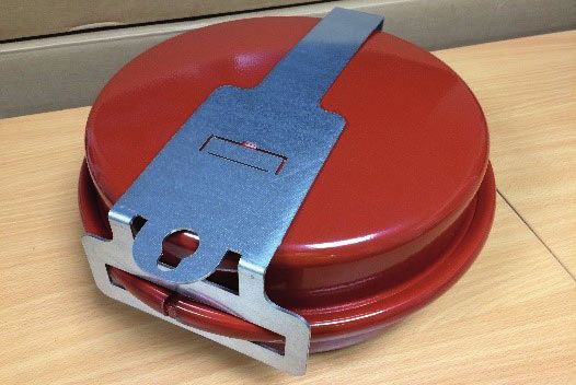
6.6 CONDENSATE TRAP
Grant Vortex Module boilers are supplied with a condensate
trap to provide the required 75 mm water seal in the condensate
! WARNING !
discharge pipe from the boiler.
Care should be taken when siting the trap such that the
The condensate trap is factory fitted inside the boiler casing - overflow outlet is readily visible and that any condensate
mounted on the inside of the left hand side panel at the rear of the overflowing from the outlet cannot cause either a hazard to
boiler - in an accessible position to allow for routine maintenance, persons or damage to surrounding property or equipment.
see Figure 6-2.
Condensate
drain pipe
from boiler
Unscrew this
cap for
Flexible hose maintenance
from outlet of access
condensing Overflow
heat exchanger warning
outlet
(with cap)
Condensate
Condensate
trap outlet to
drain
Condensate End cap
trap
Condensate
outlet to drain
Figure 6-2: Condensate trap loacation Figure 6-3: Condensate trap details
! NOTE !
Note: Check condition of hose and trap and replace if
necessary.
Section 6: Condensate Disposal Page 196.7 CONDENSATE DISPOSAL PIPEWORK 6.8 INSPECTION AND CLEANING OF TRAP
The condense trap outlet is at an angle of 48° below the The trap must be checked at regular intervals (e.g. on every
horizontal. This is to automatically gives a 3° fall on any annual service) and cleaned as necessary to ensure that it is clear
‘horizontal’ runs of condense disposal pipe. Refer to Figure 6-3 and able to operate.
and see trap outlet/pipe. The bottom bowl can be unscrewed from the trap body for
The outlet of the trap will accept 21.5 mm to 23 mm OD inspection and cleaning.
Polypropylene overflow pipe for the condensate discharge pipe. To inspect and clean the trap:
Possible routes for disposal pipework: 1. Disconnect flexible condensate hose from inlet connector.
The boiler enclosure has several 50mm diameter openings in 2. Unscrew the inlet connection nut.
both the sides and 76mm diameter openings in the base. These 3. Remove the inlet connector and nut from trap.
are designed to allow pipework to pass through, to suit the
installation. These openings can be used to allow the condensate 4. Disconnect the condensate disposal pipe from the trap outlet.
disposal pipe to exit the casing in one of the following ways: 5. Remove trap from bracket.
Side outlet - The lower opening on either side of the enclosure 6. Remove float from trap – clean if necessary.
can allow the condensate disposal pipe to be installed as follows: 7. Inspect inside of trap and clean as necessary.
• Connection to an internal stack - passing back through the 8. Check the condition of the flexible condensate hose between
wall of the house. the trap and the boiler.
• Connection to an external soil stack adjacent to the boiler. 9. Re-assemble trap, re-fit to boiler and re-connect flexible
• Discharge into an adjacent (external) drain or gulley. hose. Ensure that hose is fully pushed onto the trap inlet
• Discharge into a soakaway - with the pipe either above or connector.
below ground level.
Bottom Outlet - There are three openings in the base that can
allow the condensate disposal pipework to be installed as follows:
! CAUTION !
• Discharge into a drain or gulley beneath the boiler (e.g. a Failure to regularly check and clean the condensate trap
drain built into the concrete base for the boiler). may result in damage to the boiler and will not be covered
• Discharge into a soakaway - with pipe below ground level. by the product guarantee.
! NOTE !
When connecting plastic discharge pipe, ensure that the
pipe is fully pushed into the outlet end on the flexible hose
to prevent the possibility of leakage.
Page 20 Section 6: Condensate DisposalYou can also read