Guide to Christchurch City Council S-Paramics Modelling - Job No. 100 Standardised S-Paramics Modelling
←
→
Page content transcription
If your browser does not render page correctly, please read the page content below
Guide to Christchurch City
Council S-Paramics
Modelling

Job No. 100
Issue No 2.0 (6 July 2007)

Standardised S-Paramics Modelling
Guide to Christchurch City Council S-Paramics Modelling - Standardised S-Paramics Modelling

About This Standardised S-Paramics Modelling

 Reference:                     100
 Title:                         Guide to Christchurch City Council S-Paramics Modelling -
                                Standardised S-Paramics Modelling
 Prepared by:                   Shaun Hardcastle
 Updated by:                    Matthew Hickson/Katherine Eveleigh
 Reviewed by:                   Shaun Hardcastle

Issue     Date                 Revision Description
1.0       19 Oct 2006          Draft for discussion
1.2       9 Nov 2006           Issue 1.2 for external distribution
1.3       19 Jun 2007          Issue 1.3 for consideration
1.4       29 Jun 2007          Issue 1.4 for consideration
2.0       6 July 2007          Issue 4.0 for external distribution

Job No.100                               Issue No 2.0 (6 July 2007)

                               Printed copies of this document are uncontrolled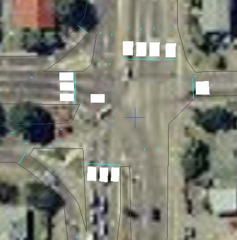
Guide to Christchurch City Council S-Paramics Modelling - Standardised S-Paramics Modelling

Contents

Table of Contents

1             Use of this Guide ................................................................................... 3
    1.1       Introduction......................................................................................... 3
    1.2       Asset .................................................................................................. 4
    1.3       Guide Convention ................................................................................. 4
    1.4       Software Versions................................................................................. 4
    1.5       Additional Media................................................................................... 5
    1.6       Feedback and Suggestions..................................................................... 5
2             File Structure ........................................................................................ 8
    2.1       Recommended Directory Structure.......................................................... 8
    2.2       External Directories .............................................................................. 9
      Demands ..................................................................................................... 9
      Digital Media ................................................................................................ 9
      Models....................................................................................................... 10
      RCA Signal Data.......................................................................................... 10
      Standard CCC Model .................................................................................... 10
    2.3       Internal Directories............................................................................. 10
      3DObjects ..................................................................................................      10
      Log ...........................................................................................................   10
      Period Specific Files .....................................................................................       11
      Signal Data ................................................................................................      11
    2.4       Directory Overview ............................................................................. 12
3             Standard Model Files............................................................................ 13
    3.1       Behaviour.......................................................................................... 13
    3.2       Buses ............................................................................................... 14
      Bus Routes and Schedules ............................................................................ 14
      Bus Stops .................................................................................................. 14
    3.3       Categories......................................................................................... 14
    3.4       Configuration ..................................................................................... 16
    3.5       Controllers ........................................................................................ 17
    3.6       Detectors .......................................................................................... 18
      Location and Shape ..................................................................................... 18
      Naming...................................................................................................... 19
    3.7       Measurements ................................................................................... 19
    3.8       Nodes ............................................................................................... 20
      Introduction ...............................................................................................      20
      Prefix ........................................................................................................   20
      TCS...........................................................................................................    21
      Methodology...............................................................................................        21
      Recommendations - Creation ........................................................................               22
Job No.100                                    Issue No 2.0 (6 July 2007)

                                  Printed copies of this document are uncontrolled
Guide to Christchurch City Council S-Paramics Modelling - Standardised S-Paramics Modelling

      Recommendations - Editing .......................................................................... 22
      Summary................................................................................................... 22
    3.9       Periods ............................................................................................. 22
    3.10      Units ................................................................................................ 23
    3.11      Vehicles ............................................................................................ 23
    3.12      Version ............................................................................................. 24
    3.13      Vshapes ............................................................................................ 24
4             General Modelling Guidelines................................................................. 24
    4.1       Use of the Standard Model ................................................................... 24
    4.2       Bounding Box .................................................................................... 24
    4.3       Model Development Notes ................................................................... 25
    4.4       Annotations File ................................................................................. 25
    4.5       Bus Stop Dwell Times.......................................................................... 25
    4.6       Links ................................................................................................ 25
      Periodic Differences ..................................................................................... 25
      GA Look Next ............................................................................................. 26
    4.7       Priorities ........................................................................................... 27
      Priority Controlled Intersections .................................................................... 27
      Signal Controlled Intersections ...................................................................... 28
    4.8       Profile Smoothing ............................................................................... 28
    4.9       Waypoints ......................................................................................... 29
    4.10      Zone Inclusion ................................................................................... 29
    4.11      Matrix Estimation ............................................................................... 29
      Survey File Input File ................................................................................... 30
5          General Network Construction Guidelines ................................................ 33
    5.1       Zones Connections ............................................................................. 33
    5.2       Right turning bays .............................................................................. 33
    5.3       Using Restrictions............................................................................... 36
    5.4       How to Cordon a Large Model and extract demands................................. 37
      Demands Extraction without Route Choice ...................................................... 37
      Demands Extraction with Route Choice........................................................... 37
      Network Cordon .......................................................................................... 37
6          Calibration Report Requirements ........................................................... 38
    6.1       Mandatory Calibration Requirements ..................................................... 39
    6.2       Optional Statistical comparison............................................................. 50
7             Peer Review Process ............................................................................ 57
    7.1       Peer Review Process ........................................................................... 64
8             Acknowledgments................................................................................ 65
    8.1       Additional Media................................................................................. 65
    8.2       baseplus ........................................................................................... 65

Appendix A : Model Development Notes (version 3.4)
Appendix B “ Model Check Files

Job No.100                                   Issue No 2.0 (6 July 2007)                              Overview Page 3

                                 Printed copies of this document are uncontrolled
Guide to Christchurch City Council S-Paramics Modelling - Standardised S-Paramics Modelling

Glossary

 Glossary, Definitions and Abbreviations
 A Model – is the directory that contains all the model data files and is what is selected
 and launched through SPx. This directory contains the sub directories required to run
 the model and store inputs and outputs.
 baseplus – New Zealand Traffic Consultancy
 baseplusFUSE (FUSE) – Communications software developed by baseplus that
 interfaces a Paramics model with SCATS.
 batch – collect data from a simulation model run
 CBD – Central Business District.
 CCC– Christchurch City Council
 DAT – Data Analysis tool within S-Paramics Suite of software to analyse model output
 FHWA – Federal Highway Administration from America, governing body for Highways
 in the US.
 Flexilink – A method of coordinating a group of signalised intersections using
 synchronized clocks and fixed time plans stored in each signal controller.
 GPS – Global Positioning System
 ITS – Intelligent Transport System
 ME – Matrix Estimation, a process of estimating a demand matrix based on observed
 inputs on turns and/or links.

 Microscopic Traffic Simulation – The modelling of individual vehicles with a start
 and end point coded, allowing the vehicle to interact with other vehicles, the road
 network infrastructure and obeying many rules of the road.
 Paramics – Microscopic Traffic Simulation software developed by SIAS known as S-
 Paramics
 Paramics Audit – A report written by an experienced Simulation Modeller that
 addresses the model structure, application and use. Findings from the audit are 'nice to
 haves' on a low level to 'compulsory changes' at the high end.
 PROM – Programmable Read Only Memory. The computer chip that contains a signal
 controller personality.
 PTIPS (Public Transport Information and Priority System) – Software developed by
 RTA to interface with SCATS that tracks the position of buses and requests priority at
 traffic signals.
 RCA - Road Controlling Authority.
 RTA – Roads and Traffic Authority (NSW), the developers of SCATS.
 run – a collection period of a simulation model output usually collected through a
 batch process.
 SCATS – Sydney Coordinated Adaptive Traffic System. The system used throughout
 Australasia to coordinate and monitor the traffic signals.
 SCATS Audit – A report written by and experienced SCATS Engineer that comments
 on the operation and performance of SCATS and highlights any errors or omissions in
 the SCATS data.
 SCATS Central Manager – Software that manages the connection of up to 64 SCATS
 Regions
 SCATS Region – Software that manages and controls up to 250 separate traffic signal
 installations. Each site can run isolated or can be coordinated with other sites using
 one of several operating modes, including fixed-time and adaptive modes. The
 adaptive modes allow the cycle times, phase splits and offsets to be determined
 dynamically to suit the prevailing traffic conditions.
 ScatsAccess – The Graphical User Interface for SCATS.
 Schema – A database or protocol used to describe a process, in this guideline it is
 used as a term specifying desirable standards for model output reporting
Job No.100                               Issue No 2.0 (6 July 2007)                           Page 1 of 76

                               Printed copies of this document are uncontrolled
Guide to Christchurch City Council S-Paramics Modelling - Standardised S-Paramics Modelling
SIAS – Developer of the simulation software suite S-Paramics.
Signal Audit – A report written by an experienced Signals Engineer that describes the
safety and operational efficiency of an RCA’s traffic signals. The Audit involves a site
visit of each signal installation being audited and the report usually contains
photographs and descriptions of the layout, hardware and signal phasing.
Signal Controller Personality – A unique program loaded into each traffic signal
controller that defines the vehicle detectors, pedestrian buttons, signal phases, which
lanterns to switch green, yellow or red at the different times and various fixed times
such as the minimum green, maximum green, yellow, all-red, pedestrian walk and
flashing clearance, etc.
Signal Peer Review – A brief report written by an experienced Signals Engineer that
reviews the design of signal installation. The report comments on items such as
layout, lane arrangements, signal lantern layout and arrangements, cycle and
pedestrian facilities and signal phasing.
Simulation Audit – A report written by an experienced simulation modeller
addressing the appropriateness and fit for purpose of a simulation model when
compared to existing/observed data in reports and models.
Simulation Peer Review – A report and assessment by an experienced simulation
modeller of an option or scheme model with comments on outputs and
appropriateness.
SLA – Select Link Analysis, used to investigate a link in a model to determine how
many trips fro each zone pass through that link for both origin and destination.
SPx– S-Paramics explorer. This is the new module interface for SIAS Paramics (release
2006.1) which is based on a standard windows format and has additional bolt on tools
that are used in this guide.
SRMS (SCATS Ramp Metering System) – software developed by RTA to control traffic
flow onto a freeway or motorway using ramp signals.
TAR – Traffic Assessment Report.
TCP/IP (Transport Control Protocol/Internet Protocol) – A set of communication
protocols for the transmission of data over a computer network.
Traffic Signal Controller – microprocessor based hardware that switches the traffic
signal lanterns between green, yellow and red.
Vehicle Detector – a loop of wire embedded in the road surface that measures a
change in inductance of a magnetic field as a vehicle passes over it.
WinTraff – Windows base software that allows the emulation of multiple (up to 250)
RTA standard signal controllers.
Job No.100 Issue No 2.0 (6 July 2007) Page 2 of 76
Printed copies of this document are uncontrolledGuide to Christchurch City Council S-Paramics Modelling - Standardised S-Paramics Modelling
1 Use of this Guide
1.1 Introduction
This guide is intended to assist an S-Paramics modeller undertaking work for
Christchurch City Council (CCC). Its purpose is to ensure consistency, quality,
connectivity and efficiency.
The provision of this guide should not be viewed as a restriction to the modellers’
development of a model but rather as a means to undertake the following:-
Provide consistency and connectivity to all CCC models
Ease of review and familiarity with model construction and methodology
Provide guidance and best practice notes
This guides intended use is in development of an S-Paramics simulation model and its
operation. In particular, it will offer guidance to those that are not familiar with the CCC
model(s). This guide includes the following:
Standard Model Structure and Development Guidelines: Sections 2 and
3 include recommendations for standard directory structure and standard
model files. This is followed by general modelling and network construction
guidelines for the development of an S-Paramics simulation model. These
guidelines are summarised in a ‘Check List’ format in Appendix B.
Calibration Report Requirements: Section 6 outlines requirements for the
Calibration Report. In particular, the inclusion of model input assumptions
(Section 6.1), mandatory calibration data (Section 6.2) and optional
calibration and statistical data analysis (Section 6.3). These requirements
are summarised in a ‘Calibration Report Specifications’ table, included as a
template in Appendix C and as an example in Section 6.4.
Peer Review Process: The standard peer review process for a micro
simulation model is defined as a flow chart in Section 7.
Whilst the guide is intended for use by consultants working on projects where CCC is the
client (and is written accordingly), its use is also recommended for any S-Paramics
projects within the CCC area, including projects where CCC is not the client but may be
Job No.100 Issue No 2.0 (6 July 2007) Page 3 of 76
Printed copies of this document are uncontrolledGuide to Christchurch City Council S-Paramics Modelling - Standardised S-Paramics Modelling
involved in the approval of a project – e.g. where Paramics model is commissioned on
behalf of developers to support resource consent applications.
1.2 Asset
The largest simulation asset that CCC own is the Christchurch CBD Model. Over time
numerous consultants have developed, tested and analysed this data set such that it is
evolving into a powerful tool.
It is envisaged that this CBD model will be further developed along with other project
models outside the CBD. These models may be integrated at some point and hence the
need for an approach that provides Paramics models within the CCC area of the desired
quality and consistency.
As such the model standard files and all the recommendations made in this guideline are
available by email request to info@baseplusworld.com; alternatively you can download
the password protected version through the secure web site at
www.baseplusworld.com/mainpages-EN/guide.htm.
1.3 Guide Convention
There are varying levels of guidance and advice. Some are simply good tips that may
save time at the point of inclusion or later on in the modelling process, some are
immovable and non-negotiable factors, and thus need to be treated, effectively, as
"Standards" rather than "Guidelines". The level of application has been implied with the
use of key words such as ‘tip’, ‘recommended’. ‘strongly recommended’ and ‘non-
negotiable’.
1.4 Software Versions
This guide is written for Paramics Version 2005.1a. Refer to section 3.12 for advice on
subsequent versions of Paramics. It is recommended that the latest version of SPx and
Dat manager be employed (currently 2007.1).
If you require software upgrades contact info@baseplusworld.com for copies of this
software or contact SIAS at Paramics@sias.com.
It is envisaged that this guide will be updated when significant variations occur in the
next software release or advised best practice is adjusted.
Job No.100 Issue No 2.0 (6 July 2007) Page 4 of 76
Printed copies of this document are uncontrolledGuide to Christchurch City Council S-Paramics Modelling - Standardised S-Paramics Modelling
1.5 Additional Media
This document is not intended to be a definitive guide to simulation modelling using
Paramics. We recommend the following background and supplementary reading in
regard to simulation model development. All of the following documents, except the
Microsimulation Consultancy Good Practice Guide, are available for download from the
secure CCC Standards web page, www.baseplusworld.com/mainpages-EN/guide.htm
SIAS – The Microsimulation Consultancy Good Practice Guide
SIAS – Reference Manual and Training Manual
Austroads – AP R 286 06 – The use and application of Microsimulation Traffic
Models
DRMB Interim advice Note on using Simulation Models
FHWA – Vol 1 – Primer, Vol 2 – Methodology, Vol 3 – Guidelines
TFL – January 2003 – Guidance Note on Microsimulation
baseplus – baseplusFUSE user and reference manual
1.6 Feedback and Suggestions
This is the third issue of this guide, and as anticipated it is more useful now through its
practical application and user feedback. The main modifications to the document have
been the inclusion of Calibration Report requirements and peer review process.
It is anticipated that this document will become more relevant over time with further
application, feedback, modification and re-issue.
As the software and functionality evolves, the guidance and methodologies may also
change. It is therefore important that your queries and feedback are received by CCC so
as to ensure that all parties that use this document are both familiar and satisfied with
the guidance offered.
Users of this guide are therefore encouraged to provide comments, suggestions for
improvement and other feedback, in writing, to paul.roberts@ccc.govt.nz.
Job No.100 Issue No 2.0 (6 July 2007) Page 5 of 76
Printed copies of this document are uncontrolledGuide to Christchurch City Council S-Paramics Modelling - Standardised S-Paramics Modelling
1.7 General Project Overview
The consultant shall adhere to the general good practice overview of a typical model
project unless otherwise agreed with the Project Manager, as shown is the following
diagram.
Figure 1: Overview of an S-Paramics consultancy project1
1
Ref: The Microsimulation consultancy good practice guide, 2005 SIAS Limited, Fig 1-2
Job No.100 Issue No 2.0 (6 July 2007) Page 6 of 76
Printed copies of this document are uncontrolledGuide to Christchurch City Council S-Paramics Modelling - Standardised S-Paramics Modelling
To achieve this good practice overview the steps in planning the model construction
should be undertaken as shown in Figure 2.
Figure 2: Plan the Model2
2
Ref: The Microsimulation consultancy good practice guide, 2005 SIAS Limited, Fig 2-1
Job No.100 Issue No 2.0 (6 July 2007) Page 7 of 76
Printed copies of this document are uncontrolledGuide to Christchurch City Council S-Paramics Modelling - Standardised S-Paramics Modelling
2 File Structure
2.1 Recommended Directory Structure
Although not all modellers have the same desire to create multiple levels of directories
and have data files buried away ten levels down from the root directory, it is strongly
advised that you adhere to the following directory structure to ensure that models
transfer and join efficiently.
There are two levels of directory structure, the first is the ‘external to’ model directory,
the second is the ‘internal to’ model directory.
The ‘external to’ directories house information on demands, digital media, models, RCA
Signal Data and the Standard CCC model. These five directories contain information that
is relevant to all models but can be either explicitly linked or do not require linking.
Figure 3: External Directory Structure and Naming
The internal directories to a model directory contain four directories, 3DObjects, Log,
period Specific Files and Signal Data. The idea behind having most inputs associated
with the model is that when you transfer the model from one location to another that all
the input files travel with the parent model directory. Within each of these internal
directories are other sub directories which are discussed below.
Job No.100 Issue No 2.0 (6 July 2007) Page 8 of 76
Printed copies of this document are uncontrolledGuide to Christchurch City Council S-Paramics Modelling - Standardised S-Paramics Modelling
Figure 4: Internal Directory Structure and Naming under ‘model’
2.2 External Directories
Demands
This folder is where the demands for the project are stored in either spreadsheets or text
files. Usually the ME models and reports are stored here. It is useful to have the
demands file under the project close to the model applications.
Digital Media
When constructing a model the first element to source before construction is usually the
aerial mapping or digital media from which your existing base model will be created. The
aerials are often provided by CCC or can be purchased from Terralink for use in
modelling. The file sizes are extremely large and require the alterations as described in
the SIAS user manual for managing and importing aerials.
The result can be large files that can through the textures and annotation file be located
anywhere in the drive. Over time, best practice has been that these files sit at the level
above the models.
It depends on how many levels of sub levels you may have above your model directory
of course, but it should be located in a common place so that all models can access
them. It is recommended that the aerials folder be located directly under the ‘models’
directory, to ensure the link to the aerials folder is retained if the entire ‘models’
directory is transferred to a different drive. If, however, this link is broken, then the link
description defined in the textures file will need to be modified to ensure access to aerial
files is retained.
Job No.100 Issue No 2.0 (6 July 2007) Page 9 of 76
Printed copies of this document are uncontrolledGuide to Christchurch City Council S-Paramics Modelling - Standardised S-Paramics Modelling
Models
Under this general directory the parent models are stored, so all model data for each
scenario can be transported, saved and perhaps version-controlled easily. It is under the
sub directories of this folder that the model scenarios are stored, of which each scenario
contains the ‘internal directories’.
RCA Signal Data
External signal data received from the RCA should be stored in this location retained in
its ‘raw’ status. From here copies can be made of the personalities, SCATS files and
databases and adjusted in accordance with the guidelines set out in the baseplusFUSE
manual. The sub levels below the RCA signal Data directory are relevant to the SCATS
files (‘SCATS inputs’), the personalities (‘Wintraff Data’), the RCA SCATS outputs (‘RCA
SCATS outputs’), where the SM and VS SCATS should be placed, and finally other files
(‘other’), where all other data like Traffic control sheets and diagrams should be placed.
Standard CCC Model
The standard CCC model is top level so as to remain unchanged by the project modelling
and is provided so that a model difference can be taken from this model to the
constructed models to check the configuration, behaviour, categories and vehicles files
to ensure that they meet the requirements of a CCC model.
2.3 Internal Directories
3DObjects
To counter the advice of centrally locating your large digital media SIAS have hard wired
all 3Ds objects into a directory under the model directory. Recently the 3Ds of
Canterbury and vehicle files have been stored for the CBD model and are available for
use for CCC projects. The tiles are not of sufficient quality from which to model from but
provide an excellent presentation backdrop.
Better quality 3Ds aerials may be available for particular projects, which are of sufficient
quality to be coded from. This might thus negate the need for any aerials folders. This
must be decided upon on a project by project basis.
Log
When you collect statistics, Paramics hard wires the outputs to a folder called ‘Log’ and
then ‘run-00X’. X being the next digit incrementally increasing from the number 1.
Because of the periodic coding for the standardised model there is a need to either make
Job No.100 Issue No 2.0 (6 July 2007) Page 10 of 76
Printed copies of this document are uncontrolledGuide to Christchurch City Council S-Paramics Modelling - Standardised S-Paramics Modelling
copies of the model thus negating the use of a single model or rename the log runs
based on what period you have modelled.
The analysis package within the S-Paramics software suite is referred to as the DAT
manager. This useful utility only reads sub directories under the ‘log’ directory of the
model that is loaded in DAT, so having any more tiered structure would make it
incompatible to use DAT with.
Period Specific Files
Because the model is split into periods for morning, inter and evening peaks you may
want to work on each individually. There is a way of manually changing the
measurements and configuration file every time that you want to change periods to
either open the model in that period or batch that model to get a run out. However to
reduce the manual input and simplify and speed the process there are period specific
files held in the AM, IP and PM directories under the Period Specific Files folder. Under
this directory are three batch files which copy the content of the relevant directory time
period to the mother directory thus ensuring on start up that the model is in the correct
period.
Signal Data
The Signal Data folder is a model specific folder that contains all the input and output
files relevant to the various 3rd party software components that allow S-Paramics and
SCATS to communicate.
For more detail read the baseplusFUSE user and reference manual on what each of these
files are and where they should be held.
It is recognised that all models may not have adaptive signals or signals at all in the
model. In which case, these directories could be removed.
There are three sub directories under signal data, namely
Paramics SCATS Outputs which is contains your model SCATS SM outputs
SCATS inputs: which are the holding area for your model and include the
System files for SCATS, the graphics database and changes to the system
files documents.
Wintraff data: holds the personalities for the signals in your model.
Job No.100 Issue No 2.0 (6 July 2007) Page 11 of 76
Printed copies of this document are uncontrolledGuide to Christchurch City Council S-Paramics Modelling - Standardised S-Paramics Modelling
2.4 Directory Overview
In summary the model directory structure that both supports the model externally and
internally is required to effectively store the inputs and outputs for a S-Paramics
simulation model. Figure 3 demonstrates a typical directory structure for a single multi
period model called ‘base’ and one option ‘option 1’. There can of course be multiple
scenarios under this models directory with another level of directories including ‘opening
year’, ‘future year 2011’, ‘option with bypass’ etc.
It is strongly recommended that an approach of minimising your copies of your largest
files but retaining portability of your model is adopted.
Figure 5: Overall Directory Structure
Job No.100 Issue No 2.0 (6 July 2007) Page 12 of 76
Printed copies of this document are uncontrolledGuide to Christchurch City Council S-Paramics Modelling - Standardised S-Paramics Modelling
3 Standard Model Files
The standard model files are the S-Paramics model input files based on the Christchurch
CBD model developed for CCC. The following is a list of the recommended starting points
for model development. If the standardised model and directory structure has been used
then the files will require no further editing.
It is strongly recommended that the files are edited within S-Paramics however it is
noted that experienced users (who as good practice dictate, make backups of the files
before editing) can edit the files with a text editor or within Excel (although the latter is
not recommended as excel converts low numbered node to link descriptions as time-
format.
The following sections only discuss files where standard CCC conventions are used.
3.1 Behaviour
The ‘aggression’ and ‘awareness’ parameters are contained in the behaviour file. The
default distribution factors of ‘1 4 11 21 26 21 11 4 1’ are to be retained for both
parameters. Varying these parameters changes how individual drivers react to the road
infrastructure and more notably each other. They are abstract keys assigned to each
vehicle, each one based on an independent normal distribution. In other words, there
are no measurable or recorded values for these parameters.
Figure 6: Aggression and Awareness Parameters
The driver behaviour representation is controlled by two factors, namely the aggression
and the awareness proxies. These factors during the development of the core software
were calibrated at time step 2. The time step is how many times a second the vehicle
drivers make decisions. The majority of the core working behind these factors and the
Job No.100 Issue No 2.0 (6 July 2007) Page 13 of 76
Printed copies of this document are uncontrolledGuide to Christchurch City Council S-Paramics Modelling - Standardised S-Paramics Modelling
data used to calibrate was observed from the European DRIVE commission study. None
of these parameters should be changed without due care, documentation and prior
agreement.
3.2 Buses
Bus Routes and Schedules
Bus routes and schedules are readily available from the Environment Canterbury web
site: http://www.metroinfo.org.nz/ .
In estimating the departure time from the first stop in your model, the closest stop to
the start should be used.
The name of the buses should use the following convention; the name of the route
followed by an ‘i’ for inbound and ‘o’ for outbound which are relative to the central major
hub. For the orbitor and metrostar use ‘c’ for clockwise and ‘a’ for anti-clockwise.
Bus Stops
All the Christchurch bus stops have numbers and it is recommended that these stops be
assigned to the appropriate model stops. Furthermore, the type of bus stop used needs
to be appropriate to each particular site. Three bus stop types can be used in the model
as defined below:
Classic – used for low frequency stops. The bus stop is defined at a single
point, where following buses are queued until they reach the specified bus
stop location point.
Fixed – used for high frequency stops where buses can stop at any of
defined points along a platform. The bus stop is defined by several points
and a bus may wait at any of them.
Dynamic - used for high frequency stops where buses can stop at any point
along a specified length of platform. The busstop is defined by a length,
where buses may wait at any point along this length.
3.3 Categories
The categories file contains speeds, major / minor, costs factors, colours of the road (for
auditing and checking), overtaking parameters, the numbers of lanes and lastly the
speed. The only other parameter that is not used in the category file is urban or
highway. Because of the definition of highway based on UK driving rules, it is strongly
Job No.100 Issue No 2.0 (6 July 2007) Page 14 of 76
Printed copies of this document are uncontrolledGuide to Christchurch City Council S-Paramics Modelling - Standardised S-Paramics Modelling
recommended that ‘highway type’ is not used for coding normal links. It may be used on
a zone connector to improve the loading operation of cars onto the network, but only
there.
For the Christchurch CBD, 24 categories have been coded, as summarised in Table 1
below. Grouped in lanes of 4, the speeds range from 55 kph to 20 kph. The ranking goes
from 55 kph major arterial distributor roads to 20kph for quiet, traffic-calmed, low
attraction access roads.
Application of these categories is strongly recommended to any model development as
categories are one of the hardest matches (with the exception of node numbers) to do.
Where the modeller considers that the cost factors or other parameters may be
inappropriate CCC require a "duplicate" of an existing category to be taken and modified
accordingly. For example, if a Major 55kph was appropriate but a Cost Factor of 0.9
deemed more appropriate, then the modeller should create category 29 (or higher) from
category 1-4. This will assist in auditing non-standard elements of models.
Any additional categories created should be reported to CCC and consideration will be
given to inclusion with subsequent issues of the standard categories file.
Category Cost Major/ Speed Description Colour
Factor Minor
1 -4 0.8 Major 55 Main Distributors(Bealey, red
Moorhouse, Fitzgerald)
5 -8 0.8 Major 50 One Ways orange
9-12 1.0 Major 45 Secondary Major green
13-16 1.3 Minor 35 Access major purple
17-20 1.6 Minor 25 Access minor, calmed Light purple
21-24 1.8 Minor 20 Loading, access only yellow
25-28 1.0 Major 40 Special Speed Zone for pink
Schools
Table 1: Category Classification
The above classification reflects the practical function of the road rather than the
statutory hierarchy as presented in the regional plan for Canterbury and Christchurch. In
particular, note that the major/minor description has no correlation to City Plan
hierarchy, but rather affects the routeing behaviour for that link. In general sign posted
routes should be composed of major links and other routes of minor links.
Job No.100 Issue No 2.0 (6 July 2007) Page 15 of 76
Printed copies of this document are uncontrolledGuide to Christchurch City Council S-Paramics Modelling - Standardised S-Paramics Modelling
3.4 Configuration
The configuration file holds the key operational input parameters to the model operation.
The time step should be retained at ‘2’. The default release style of precise should be
retained. A standard definition of queue criteria has been developed as follows:
General: Vehicle queued when: Speed 7 kph, gap 5 m, both toggled; Vehicle
no longer queued when: Speed 7.5 kph, gap 6 m, either toggled
Other settings: min length 2, recurse 8, toggle off ‘include signalised links in
non signal queues’.
Multiple queues: Joining all the queues together toggled.
The mean headway should be set to 0.8.
A network minimum gap at 0.8 should be used for versions 2005.1A and earlier, and a
value of 1.6 should be used for version 2006.1 an onwards. (Note that version 2006.1 is
not currently recommended for us, see 3.12)
NZ left turn should be enabled.
The following signal settings should be used:
Signals red to green time should be set to 0.0 seconds [default 2.0]
Signal movement start delay should be set to 1.0 seconds
Signal movement stop delay should be set to 4.0 seconds
Signals green to red time should be set to 2.0 seconds
Job No.100 Issue No 2.0 (6 July 2007) Page 16 of 76
Printed copies of this document are uncontrolledGuide to Christchurch City Council S-Paramics Modelling - Standardised S-Paramics Modelling
Figure 7: Recommended Signal Settings
Other parameters included in the configuration file, such as feedback period and
coefficient, cost coefficients, start time, simulation time and the colours can change as
per model development requirements but any variation to the standard model file must
be highlighted within the calibration report, with reasons given. These parameters are
further discussed in section 4.11 of this report.
The configuration file is one of the three periodic files held in the periodic file directories
and should be edited in all three if any changes are to be made.
3.5 Controllers
The controllers file is set to have the SNMP port set to 2100 to ensure that the model is
configured to talk to FUSE and then on to Wintraff and SCATS. This file has no bearing
on operation of the model and should therefore be left intact.
Figure 8: Controllers File
Job No.100 Issue No 2.0 (6 July 2007) Page 17 of 76
Printed copies of this document are uncontrolledGuide to Christchurch City Council S-Paramics Modelling - Standardised S-Paramics Modelling
3.6 Detectors
Location and Shape
Current best practice is to code detectors at 5.0 m in length and that the end of the
detector is placed adjacent to the stopline.
Where an exit detector is present the end of the detector is 11 metres forward of the
stop line, meaning that the start of the loop is 6 metres from the stop line exit. This is
illustrated in the following example diagram.
11m
5m
Figure 9: Example Detector Layout at Intersection
The detector should be entered as a shape not on the link, this allows the detector to be
placed anywhere in the model, not just along the link boundary. This is important for
detectors over nodes that are not in the link.
In coding detectors for use with SCATS, the following is offered as good practice:
Ensure that the detector is completely within the link
Test each detector with vehicles to ensure that each vehicle is detected and
no errors are reported on the detector
Job No.100 Issue No 2.0 (6 July 2007) Page 18 of 76
Printed copies of this document are uncontrolledGuide to Christchurch City Council S-Paramics Modelling - Standardised S-Paramics Modelling
Naming
The detector naming works on the principle of ‘TCS number_detector number’, for
example at TCS 201 and with detector number 7 the detector name is ‘201_7’.
It serves as a check that if you enter the same detector name as the TCS number and
detector then the two rows should be the same, this allows then for detectors to be
checked quickly and also to be named differently if required.
3.7 Measurements
Although the periods change and so do the collection times, a standard measurement
file is evolving to meet the requirements of most modelling requirements. It is still
evolving as are the tools with which to analyse the outputs.
The most frustrating aspect is that if you require a 3 hour model link flow and a 1 hour
link flow through DAT you must collect a 3 hour model and then run again to get the 1
hour, there is no method as yet of aggregating data in DAT. However, the 2007.1
version, due for release in July, is reported to have the functionality for time aggregation
in DAT. The external method of using excel is achievable but it comes with its own set of
problems.
CCC are currently investigating ways to standardise the measurements and reporting of
Paramics, as are most consultants. The XLM schema (a standard or guideline template
for reporting) prepared by the FHWA may provide guidance to this guideline and is
currently being investigated.
The measurement file is one of the three periodic files held in the periodic file directories
and should be edited in all three if any changes are to be made, unless it is simply that
the collection time changes.
The following is a recommended minimum and by no means exhaustive list of statistics
to be collated when running a model.
Snapshots; usually collated at 15 minute intervals
Turncounts: interval dependant on statistics that require collating; baseplus,
as a standard collate these in five minute intervals and aggregate up to
desired periodic intervals using excel.
Within the measurements GUI it is imperative to ensure that if bus statistics are required
that the buses themselves are included in the output files. File>>Buses will enable the
modeller to select or deselect the buses to be included in the output statistics.
Job No.100 Issue No 2.0 (6 July 2007) Page 19 of 76
Printed copies of this document are uncontrolledGuide to Christchurch City Council S-Paramics Modelling - Standardised S-Paramics Modelling
Figure 10: Bus Inclusion/Exclusion window
3.8 Nodes
Introduction
It is the intention to allow seamless merging of S-Paramics models created for
Christchurch City Council. The nodes file is one of the core files that must be both
uniquely referenced and be on the same co-ordinate system. Every modelling
component starts with the node, from link, to kerb to stop line to mapping of signal
movements.
Prefix
To enable seamless transition with unique referencing a prefix to the node is highly
desirable so that it remains unique but also when opening files in Excel (particularly
output) the lower node descriptions do not get converted to the time format.
The prefix could be as simple as a letter or combination of letters to assist with project
identification. To manage the prefix database a HTML page is presented in the CCC
standards area which contains all the approved CCC node prefixes at the outset of
project, unless specified in the brief. Approval should be sought from CCC on the prefix
to be adopted for a particular model.
NOTE: currently the web page is not created, however the following are reserved:
Job No.100 Issue No 2.0 (6 July 2007) Page 20 of 76
Printed copies of this document are uncontrolledGuide to Christchurch City Council S-Paramics Modelling - Standardised S-Paramics Modelling
CCC project Prefix for Nodes
CBD a
Colombo Street Bus Priority bpc
Papanui Road Bus Priority bpp
Queenspark Bus Priority bpq
Bealey Avenue None required part of CBD with
existing prefix ‘a’ as above
FerryMead Bridge fm
Table 2: Node Prefix Table
TCS
Another useful node naming convention is to name the signalised node the TCS (traffic
control System) number, for instance the Tuam and Montreal intersections in the
Christchurch CBD model is TCS 2, the nodes for this junction are nodes 2 and 2a. All the
TCS junction names are represented in the CBD model as per the TCS name, so the
traffic engineer who is familiar with the network can navigate quickly around the model.
In addition cross checking the signal mapping and movements as well as a systematic
numbering system for signal nodes is highly desirable.
Methodology
Retrospective naming of nodes is increasingly difficult based on the number of coded
inputs, as stated in the methodology everything is referenced directly to the node or to
the link which is referenced to the node. It is possible to achieve a retrospective prefix
naming convention but numerous files must be edited, cross referenced and resolving
the errors can be time consuming.
Rather than retrospectively fit the model a suggestion is made to create nodes
unattached to another node, save the model and rename the node externally to S-
Paramics using a suitable text editor. A spare node repository is suggested in the model
form to allow mass renaming for use through model calibration.
Job No.100 Issue No 2.0 (6 July 2007) Page 21 of 76
Printed copies of this document are uncontrolledGuide to Christchurch City Council S-Paramics Modelling - Standardised S-Paramics Modelling
Recommendations - Creation
In the standardised model download create additional nodes without
attaching them.
rename in a text editor all the nodes with a pre-agreed prefix
rename some of the those nodes with the actual TCS name (known before
model creation)
Place your TCS nodes in the model, place the first pass nodes in the model.
Connect the nodes with the appropriate link classification.
Recommendations - Editing
Without a prefix, splitting a link will create an automatically named node, this of course
will not have a prefix. It is suggested then if a new node is to be inserted onto an
existing link, then that link is deleted, a prefixed node (previously created) is placed and
then re-connected to the existing prefixed nodes.
Summary
It is accepted that the additional time in agreeing a prefix, checking that the prefix
doesn’t exist anywhere else, the creation and renaming of nodes and then manually
placing them is time consuming. However, the time saving if and when the model is
merged will become apparent. Please remember that the prefix naming is only required
if ultimately it is to be merged.
3.9 Periods
The periodic files are related to the times of the day that require modelling. The periods
file contains the period number, name and start time. It is recommended that you
adhere to these periods as they match the CBD. Remembering that changes in the
periods affects the following files: priorities.X, links.X, demands.X (where X denotes the
period) and also affects how the profiles assignments work in the profile and matrix files.
Job No.100 Issue No 2.0 (6 July 2007) Page 22 of 76
Printed copies of this document are uncontrolledGuide to Christchurch City Council S-Paramics Modelling - Standardised S-Paramics Modelling
Figure 11: Periodic Setup in S-Paramics
The periods file should not be edited externally. S-Paramics does a very tidy job of
cleaning up surplus files and reporting differences between periods.
3.10 Units
The units file contains the preferred measurement system for that model. The
recommended mode for New Zealand is metric and thus the units file should not change.
3.11 Vehicles
The standard vehicles file contains cars, cars with trailers, small, light and heavy good
vehicles, B-Trains, Large Articulated vehicles, single deck buses of various colours to
depict which Bus Exchange platform they use and even the Christchurch Tram. CCC
believes this is a comprehensive vehicle type list and any variation to this file should be
reported in the calibration documentation.
It is accepted that vehicle proportions may vary by destination. Such differences may be
modelled through use of different matrices and consequent vehicle types which allow the
use of vehicle destination restrictions. This is permitted within reason accepting that it
dramatically increases the processing time due to the increase in number of routing
tables.
The vehicle proportions attributed to each matrix total have been derived from other
studies and it is permitted to change these percentages based on observed data or
estimates with agreement of the CCC project manager.
Job No.100 Issue No 2.0 (6 July 2007) Page 23 of 76
Printed copies of this document are uncontrolledGuide to Christchurch City Council S-Paramics Modelling - Standardised S-Paramics Modelling
3.12 Version
The latest S-Paramics version is currently version 2007.1, recently released in July 2007.
However, it is advised that S-Paramics version 2005.1a be used for all modelling
undertaken for CCC, until later versions have been fully evaluated.
It is recommended that SPx Version 2007.1 be used. In this version of SPx the Paramics
version selected will, by default, be the version defined in the versions file of the model.
Users should be aware that BaseplusFUSE will run the Paramics version that is set in the
baseplusFUSE configuration file, rather than automatically using the version of the model
selected.
3.13 Vshapes
The associated vehicle shapes file allows for the vehicle shapes to be seen for
presentational 3D shots and should not be adjusted unless you can find better car
shapes than supplied!
4 General Modelling Guidelines
4.1 Use of the Standard Model
It is strongly advised that you start with the standardised model setup so all the
parameters as described in this guide are set. If the model development has commenced
copy and over write the files required, such as configuration, categories (with care!),
vehicles and behaviour.
Then use the ‘model difference’ reporter in the SPx tools box and compare your model to
the issued standard CCC model, this will report on all the differences between your
model and the standard model. Focus on the vehicles, categories, configuration, and
behaviour files.
4.2 Bounding Box
There exists a new tool named ‘model mover’ within the SPx software that allows whole
models to be moved by whatever X,Y co-ordinate required. There are two methods that
can be employed using this new tool in constructing the network.
1. Work with the co-ordinate system from the standard model, this way the reference to
the CBD is absolute.
2. Work from 0,0 and then on completion move the model using this new facility to
match the CBD.
Job No.100 Issue No 2.0 (6 July 2007) Page 24 of 76
Printed copies of this document are uncontrolledGuide to Christchurch City Council S-Paramics Modelling - Standardised S-Paramics Modelling
The second method would result in a common point being identified then the new model
translated to the X an Y. It is assumed that the new model would be orientated to the
north as there is currently no rotational functionality in the model mover.
4.3 Model Development Notes
Appendix A contains the baseplus model development notes version 3.4 which are a
prompt for the modeller to document non standard changes to model form, background
information on the demands, study area, purpose etc. This provides the platform for a
calibration report and if used early in the project development, a model scoping report.
4.4 Annotations File
The annotations file contains mainly detectors and road names. This file requires no
standardisation, but it is recommended that a good description of the model is entered
however to allow for easy identification.
4.5 Bus Stop Dwell Times
If the focus of the model is on public transport regarding buses, then it would be
expected that the model will represent on-street bus operation as accurately as possible.
The aspect of bus stop dwell times may be particularly important if future scenarios
involve changes to bus stop dwell times or change the way buses merge with the
general traffic stream.
In this regard, consideration should be given to the following areas
What actions the surveyed bus stop dwell times include and exclude.
The time taken for buses to merge into the general traffic stream, and how
this is modelled in S-Paramics.
Whether buses that do not stop at every bus can be coded to “pass by” the
bus stop, as opposed to simply including the pass time of “zero” in the set of
data that is averaged to make the bus stop dwell time.
4.6 Links
Periodic Differences
As one of the time dependant period files, the links file period 1 holds all the link data.
Any subsequent deviations from “links.1” are stored in that relative period file. This is
Job No.100 Issue No 2.0 (6 July 2007) Page 25 of 76
Printed copies of this document are uncontrolledGuide to Christchurch City Council S-Paramics Modelling - Standardised S-Paramics Modelling
particularly useful when modelling clearways or time dependant operation lanes, say for
instance HOV or bus only lanes.
Often link attributes are unintentionally changed in periods other than period 1 when the
change is intended to be applied to all periods. The modeller should regularly check
periodic differences to ensure such errors are remedied and avoided. This is done
through the Editor>> Show Changes as shown in the figure below
Figure 12: Periodic Differences Window
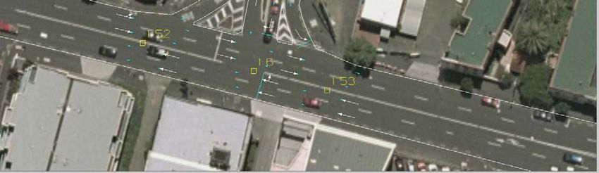
GA Look Next
An often overlooked link flag is GA look next. GA look next should be used on links that
are short links upstream from the minor approach on priority intersections.
The figure below illustrates where GA look next should be applied a simple T-
intersection.
Job No.100 Issue No 2.0 (6 July 2007) Page 26 of 76
Printed copies of this document are uncontrolledGuide to Christchurch City Council S-Paramics Modelling - Standardised S-Paramics Modelling
Apply GA look next
Apply GA look next
Apply GA look
Figure 13: GA Look Next Function Example
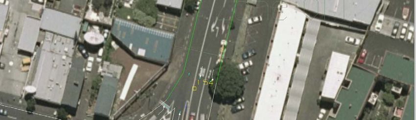
4.7 Priorities
Priority Controlled Intersections
It is imperative to ensure all intersections are given the correct priority, especially given
the New Zealand Left Turn rule application. An example of a four arm intersection with
priorities is presented in the figure below as a guide. Priorities for priority controlled
intersections should not change between periods unless you have time dependant
movement bans.
Figure 14: Four Arm Intersection Priority Example
Job No.100 Issue No 2.0 (6 July 2007) Page 27 of 76
Printed copies of this document are uncontrolledYou can also read