Hardware Maintenance Manual - Lenovo
←
→
Page content transcription
If your browser does not render page correctly, please read the page content below
Hardware Maintenance Manual
Note: Before using this information and the product it supports, be sure to read the general information
under Appendix A “Notices” on page 61.

Second Edition (June 2021)

© Copyright Lenovo 2020, 2021.
LIMITED AND RESTRICTED RIGHTS NOTICE: If data or software is delivered pursuant to a General Services
Administration “GSA” contract, use, reproduction, or disclosure is subject to restrictions set forth in Contract No. GS-
35F-05925.
Contents

About this manual . . . . . . . . . . . . iii                                    Intermittent problems . . . . . . . . . . .                    31
                                                                                 Undetermined problems . . . . . . . . .                        32
Chapter 1. Safety information . . . . . . 1
General safety . . . . . . . . . . . . . .                          . . 1    Chapter 5. Locations . . . . . . . . . 33
Electrical safety . . . . . . . . . . . . . .                       . . 1    Overview . . . . . . . .       .   .   .   .   .   .   .   .   .   33
Safety inspection guide . . . . . . . . . . .                       . . 3    Locating FRUs and CRUs . .     .   .   .   .   .   .   .   .   .   33
Handling devices that are sensitive to electrostatic                             Major FRUs and CRUs .      .   .   .   .   .   .   .   .   .   34
discharge . . . . . . . . . . . . . . . .                           . . 3        Other parts . . . . . .    .   .   .   .   .   .   .   .   .   36
Grounding requirements . . . . . . . . . .                          . . 4    Looking up FRU information .   .   .   .   .   .   .   .   .   .   36
Safety notices (multilingual translations) . . . .                  . . 4
                                                                             Chapter 6. FRU replacement
Chapter 2. Important service                                                 notices . . . . . . . . . . . . . . . . . 37
information . . . . . . . . . . . . . . . 21                                 Service tool kit . . . . . . . . . . . . . . .                     37
Strategy for replacing FRUs . . . . . . . . .                       .   21   Screw notices . . . . . . . . . . . . . . .                        37
     Important notice for replacing a system                                 Retaining serial numbers . . . . . . . . . . .                     38
     board . . . . . . . . . . . . . . . .                          .   21
     How to use error message . . . . . . . .                       .   22   Chapter 7. Removing or replacing a
Strategy for replacing FRUs for CTO, special bid                             FRU. . . . . . . . . . . . . . . . . . . 39
model, and standard models. . . . . . . . .                         .   22
                                                                             General guidelines. . . . . . . . . . .                .   .   .   39
     Product definition . . . . . . . . . . .                       .   22
                                                                             Before servicing the computer . . . . . .              .   .   .   40
     FRU identification . . . . . . . . . . .                       .   22
                                                                                 Disabling the built-in battery . . . . .           .   .   .   40
Chapter 3. General checkout . . . . . 23                                         Removing the Nano-SIM-card tray . .                .   .   .   40
What to do first . . . . . . . . . . . . . .                        .   23   1010 Folio cover set . . . . . . . . . .               .   .   .   41
Checkout guide . . . . . . . . . . . . . .                          .   24   1020 Smart glass and adhesive tapes . . .              .   .   .   45
   Diagnosing problems . . . . . . . . . .                          .   24   1030 Access door . . . . . . . . . . .                 .   .   .   47
   Quick test programs . . . . . . . . . .                          .   24   1040 Support bracket . . . . . . . . .                 .   .   .   47
   UEFI diagnostic program . . . . . . . .                          .   25   1050 System board assembly . . . . . .                 .   .   .   48
   Bootable diagnostic programs . . . . . .                         .   25   1060 Thermal sub-spreader . . . . . . .                .   .   .   53
Power system checkout . . . . . . . . . .                           .   26   1070 M.2 solid-state drive . . . . . . . .             .   .   .   54
   Checking the ac power adapter . . . . . .                        .   26   1080 Wireless WAN card . . . . . . . .                 .   .   .   55
   Checking the built-in battery and operational                             1090 USB-C sub cards and USB-C sub card
   charging . . . . . . . . . . . . . . .                           .   27   cable . . . . . . . . . . . . . . . .                  . . .       56
                                                                             1110 OLED assembly with frame cover and
Chapter 4. Related service                                                   miscellaneous parts . . . . . . . . . .                . . .       58
information . . . . . . . . . . . . . . . 29
                                                                             Appendix A. Notices . . . . . . . . . . 61
Reset or restore Windows .      .   .   .   .   .   .   .   .   .   .   29
Using passwords . . . .         .   .   .   .   .   .   .   .   .   .   29   Appendix B. Abbreviation and
Symptom-to-FRU index .          .   .   .   .   .   .   .   .   .   .   30   acronym table . . . . . . . . . . . . . 63
    Numeric error codes .       .   .   .   .   .   .   .   .   .   .   31

© Copyright Lenovo 2020, 2021                                                                                                                    i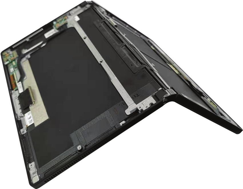
ii Hardware Maintenance Manual

About this manual
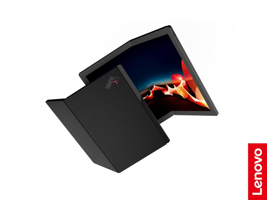
This manual contains service and reference information for the following ThinkPad® products.
Machine Machine type (MT)
ThinkPad X1 Fold Gen 1
20RK and 20RL
ThinkPad X1 Fold Gen 1 5G
Important:
• This manual is intended only for trained service technicians who are familiar with ThinkPad products. Use
this manual along with the advanced diagnostic tests to troubleshoot problems effectively.
• Before servicing a ThinkPad product, be sure to read all the information under Chapter 1 “Safety
information” on page 1 and Chapter 2 “Important service information” on page 21.
© Copyright Lenovo 2020, 2021 iii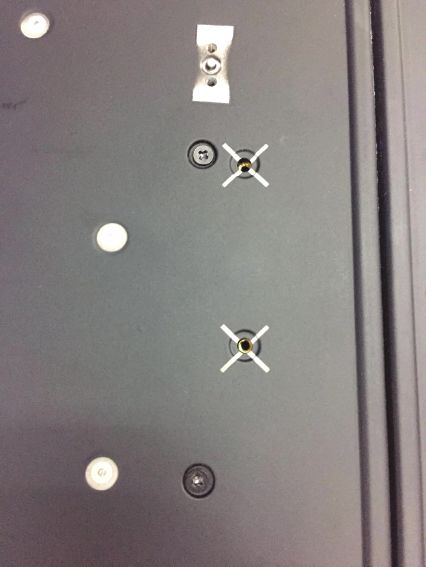
iv Hardware Maintenance Manual
Chapter 1. Safety information
This chapter presents following safety information that you should be familiar with before you service a
ThinkPad computer.
• “General safety” on page 1
• “Electrical safety” on page 1
• “Safety inspection guide” on page 3
• “Handling devices that are sensitive to electrostatic discharge” on page 3
• “Grounding requirements” on page 4
• “Safety notices (multilingual translations)” on page 4

General safety
Follow these rules to ensure general safety:

• Observe good housekeeping in the area of the machines during and after maintenance.
• When lifting any heavy object:
    1. Make sure that you can stand safely without slipping.
    2. Distribute the weight of the object equally between your feet.
    3. Use a slow lifting force. Never move suddenly or twist when you attempt to lift.
    4. Lift by standing or by pushing up with your leg muscles; this action removes the strain from the
       muscles in your back. Do not attempt to lift any object that weighs more than 16 kg (35 lb) or that you
       think is too heavy for you.
• Do not perform any action that causes hazards to the customer, or that makes the equipment unsafe.
• Before you start the machine, make sure that other service technicians and the customer's personnel are
  not in a hazardous position.
• Place removed covers and other parts in a safe place, away from all personnel, while you are servicing the
  machine.
• Keep your toolcase away from walk areas so that other people will not trip over it.
• Do not wear loose clothing that can be trapped in the moving parts of a machine. Make sure that your
  sleeves are fastened or rolled up above your elbows. If your hair is long, fasten it.
• Insert the ends of your necktie or scarf inside clothing or fasten it with a nonconductive clip, about 8
  centimeters (3 inches) from the end.
• Do not wear jewelry, chains, metal-frame eyeglasses, or metal fasteners for your clothing.

   Attention: Metal objects are good electrical conductors.
• Wear safety glasses when you are working in conditions that might be hazardous to your eyes. The
  conditions include hammering, drilling, soldering, cutting wire, attaching springs, using solvents, and so
  on.
• After service, reinstall all safety shields, guards, labels, and ground wires. Replace any safety device that
  is worn or defective.
• Reinstall other parts that you have removed.

Electrical safety
Observe the following rules when working on electrical equipment.

© Copyright Lenovo 2020, 2021                                                                                     1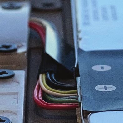
Important:
• Use only approved tools and test equipment. Some hand tools have handles covered with a soft material
  that does not insulate you when working with live electrical currents.
• Many customers have, near their equipment, rubber floor mats that contain small conductive fibers to
  decrease electrostatic discharges. Do not use this type of mat to protect yourself from electrical shock.
• Find the room emergency power-off (EPO) switch, disconnecting switch, or electrical outlet. If an electrical
  accident occurs, you can then operate the switch or disconnect the power cord quickly.
• Do not work alone under hazardous conditions or near equipment that has hazardous voltages.
• Disconnect all power before:
  – Performing a mechanical inspection
  – Working near power supplies
  – Removing or installing main units
• Before you start to work on the machine, disconnect the power cord. If you cannot unplug it, power off the
  wall box that supplies power to the machine, and lock the wall box in the off position.
• If you work on a machine that has exposed electrical circuits, observe the following precautions:
  – Ensure that another person, familiar with the power-off controls, is near you.

      Attention: Another person must be there to switch off the power, if necessary.
    – Use only one hand when working with powered-on electrical equipment; keep the other hand in your
      pocket or behind your back.

       Attention: An electrical shock can occur only when there is a complete circuit. By observing the above
       rule, you may prevent a current from passing through your body.
    – When using testers, set the controls correctly and use the approved probe leads and accessories for
       that tester.
    – Stand on suitable rubber mats (obtained locally, if necessary) to insulate you from grounds such as
       metal floor strips and machine frames.
    Observe the special safety precautions when you work with very high voltages; Instructions for these
    precautions are in the safety sections of maintenance information. Use extreme care when measuring high
    voltages.
• Regularly inspect and maintain your electrical hand tools for safe operational condition.
• Do not use worn or broken tools and testers.
• Never assume that power has been disconnected from a circuit. First, check that it has been powered off.
• Always look carefully for possible hazards in your work area. Examples of these hazards are moist floors,
  nongrounded power extension cables, power surges, and missing safety grounds.
• Do not touch live electrical circuits with the reflective surface of a plastic dental mirror. The surface is
  conductive; such touching can cause personal injury and machine damage.
• Do not service the following parts with the power on when they are removed from their normal operating
  places in a machine:
  – Power supply units
  – Pumps
  – Motor generators
  – Similar units to listed above
  This practice ensures correct grounding of the units.
• If an electrical accident occurs:
  – Use caution; do not become a victim yourself.
  – Switch off power.
  – Send another person to get medical aid.

2    Hardware Maintenance Manual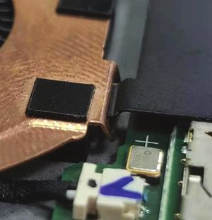
Safety inspection guide
The purpose of this inspection guide is to assist you in identifying potentially unsafe conditions. As each
machine was designed and built, required safety items were installed to protect users and service
technicians from injury. This guide addresses only those items. You should use good judgment to identify
potential safety hazards due to attachment of non-ThinkPad features or options not covered by this
inspection guide.

If any unsafe conditions are present, you must determine how serious the apparent hazard could be and
whether you can continue without first correcting the problem.

Consider these conditions and the safety hazards they present:
• Electrical hazards, especially primary power (primary voltage on the frame can cause serious or fatal
  electrical shock)
• Explosive hazards, such as a damaged CRT face or a bulging capacitor
• Mechanical hazards, such as loose or missing hardware

To determine whether there are any potentially unsafe conditions, use the following checklist at the
beginning of every service task. Begin the checks with the power off and the power cord disconnected.

Checklist:
 1. Check exterior covers for damage (loose, broken, or sharp edges).
 2. Turn off the computer.
 3. Disable the built-in battery. For the instruction on how to disable the built-in battery, see “Disabling the
    built-in battery” on page 40.
 4. Disconnect the power cord.
 5. Check the power cord for the following:
    a. Make sure that a third-wire ground connector is in good condition. Use a meter to measure the third-
       wire ground continuity. Ensure that the continuity between the external ground pin and the frame
       ground is 0.1 ohm or less.
    b. The power cord is the type specified in the parts list.
    c. Insulation is not frayed or worn.
 6. Remove the LCD module assembly.
 7. Check for cracked or bulging built-in batteries.
 8. Check for any obvious non-ThinkPad alterations. Use good judgment as to the safety of any non-
    ThinkPad alterations.
 9. Check inside the unit for any obvious unsafe conditions, such as metal filings, contamination, water or
    other liquids, or signs of fire or smoke damage.
10. Check for worn, frayed, or pinched cables.
11. Check that the built-in battery fasteners (screws or rivets) have not been removed or tampered with.

Handling devices that are sensitive to electrostatic discharge
Any computer part containing transistors or integrated circuits (ICs) should be considered sensitive to
electrostatic discharge (ESD). ESD damage can occur when there is a difference in charge between objects.
Protect against ESD damage by equalizing the charge. So that the machine, the part, the work mat, and the
person handling the part are all at the same charge.

                                                                                    Chapter 1. Safety information   3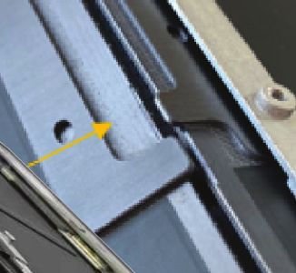
Notes:
    1. Use product-specific ESD procedures when they exceed the requirements noted here.
    2. Make sure that the ESD protective devices you use have been certified (ISO 9000) as fully effective.

When handling ESD-sensitive parts:
• Keep the parts in protective packages until they are inserted into the product.
• Avoid contact with other people.
• Wear a grounded wrist strap against your skin to eliminate static on your body.
• Prevent the part from touching your clothing. Most clothing is insulative and retains a charge even when
  you are wearing a wrist strap.
• Use a grounded work mat to provide a static-free work surface. The mat is especially useful when
  handling ESD-sensitive devices.
• Select a grounding system, such as those listed below, to provide protection that meets the specific
  service requirement.

     Note: The use of a grounding system to guard against ESD damage is desirable but not necessary.
     – Attach the ESD ground clip to any frame ground, ground braid, or green-wire ground.
     – When working on a double-insulated or battery-operated system, use an ESD common ground or
       reference point. You can use coax or connector-outside shells on these systems.
     – Use the round ground prong of the ac plug on ac-operated computers.

Grounding requirements
Electrical grounding of the computer is required for operator safety and correct system function. Proper
grounding of the electrical outlet can be verified by a certified electrician.

Safety notices (multilingual translations)
The safety notices in this section are provided in the following languages:
• English
• Arabic
• Brazilian Portuguese
• French
• German
• Hebrew
• Japanese
• Korean
• Spanish
• Traditional Chinese

DANGER

4     Hardware Maintenance Manual
DANGER
DANGER
DANGER
DANGER
DANGER
Chapter 1. Safety information 5DANGER DANGER 6 Hardware Maintenance Manual
PERIGO

         Chapter 1. Safety information   7
PERIGO PERIGO PERIGO PERIGO 8 Hardware Maintenance Manual
PERIGO

PERIGO

PERIGO

DANGER

DANGER

         Chapter 1. Safety information   9
DANGER DANGER DANGER DANGER DANGER 10 Hardware Maintenance Manual
DANGER

VORSICHT

VORSICHT

VORSICHT

VORSICHT

           Chapter 1. Safety information   11
VORSICHT VORSICHT VORSICHT VORSICHT 12 Hardware Maintenance Manual
Chapter 1. Safety information 13
14 Hardware Maintenance Manual
Chapter 1. Safety information 15
16 Hardware Maintenance Manual
Chapter 1. Safety information 17
18 Hardware Maintenance Manual
Chapter 1. Safety information 19
20 Hardware Maintenance Manual
Chapter 2. Important service information
This chapter introduces following important service information that applies to all machine types supported
by this manual:
• “Strategy for replacing FRUs” on page 21
   – “Important notice for replacing a system board” on page 21
   – “How to use error message” on page 22
• “Strategy for replacing FRUs for CTO, special bid model, and standard models” on page 22
   – “Product definition” on page 22
   – “FRU identification” on page 22

Important:
• Advise customers to visit the Lenovo® Support Web site at https://support.lenovo.com. The customers can
  view the software fixes, download the drivers, and see the instructions for installing the drivers. For
  additional assistance, customers might call the Lenovo Customer Support Center. Telephone numbers for
  the Lenovo Support Center are available at:
  https://pcsupport.lenovo.com/supportphonelist
• Service training documents, for example the videos that show the FRU removals or replacements, are
  provided to Lenovo authorized service technicians. The training documents are available at:
  https://www.lenovoservicetraining.com/ion/

Strategy for replacing FRUs

Before replacing parts:
Ensure that all software fixes, drivers, and UEFI BIOS downloads are installed before replacing any FRUs
listed in this manual.

After a system board is replaced, ensure that the latest UEFI BIOS is loaded to the system board before
completing the service action.

To download software fixes, drivers, and UEFI BIOS, go to https://support.lenovo.com and follow the
instructions on the screen.
• If you are instructed to replace a FRU but the replacement does not correct the problem, reinstall the
  original FRU before you continue.
• Some computers have both a processor board and a system board. If you are instructed to replace either
  the processor board or the system board, and replacing one of them does not correct the problem,
  reinstall that board, and then replace the other one.
• If an adapter or a device consists of more than one FRU, any of the FRUs may be the cause of the error.
  Before replacing the adapter or device, remove the FRUs, one by one, to see if the symptoms change.
  Replace only the FRU that changed the symptoms.

Attention: The setup configuration on the computer you are servicing may have been customized. Running
Automatic Configuration may alter the settings. Note the current configuration settings (using the View
Configuration option); then, when service has been completed, verify that those settings remain in effect.

Important notice for replacing a system board
Attention: When handling a system board:
• Do not drop a system board or apply any excessive force to it.

© Copyright Lenovo 2020, 2021                                                                               21
• Avoid rough handling of any kind.
• Avoid bending a system board and hard pushing to prevent cracking at each Ball Grid Array (BGA)
  chipset.

How to use error message
Use the error codes displayed on the screen to diagnose failures. If more than one error code is displayed,
begin the diagnosis with the first error code. Whatever causes the first error code may also cause false error
codes. If no error code is displayed, see whether the error symptom is listed in the Symptom-to-FRU Index
for the computer you are servicing.

Strategy for replacing FRUs for CTO, special bid model, and standard
models
This topic provides information about the model types and FRU identification.

Product definition
This topic introduces different model types and how to identify each type.

Dynamic Configure To Order (CTO)
This model provides the ability for a customer to configure a Lenovo solution from a web site, and have this
configuration sent to fulfillment, where it is built and shipped directly to the customer. The machine label and
eSupport will load these products as the 4-character MT, 4-character model and 2-character country code.
The model is “CTO1” and the default country code is “WW” (example: 20AACTO1WW).

Special bid model
This model is a unique configuration that has been negotiated between Lenovo and the customer. A unique
MTM consists of a 4-character MT, a 4-character model, and a numeric 2-character country code is provided
to the customer to place orders (example: 20AA000955). The country code assigned is numeric and does not
designate a specific country or region. The custom model factsheet for the MTM indicates which country the
special bid MTM is set up for. Special bid offering is not generally announced.

Standard model
Standard models (fixed configuration) are announced and offered to all customers. The MTM portion of the
machine label consists of a 4-character MT, a 4-character model, and an alphabetic 2-character country
code. The country code assigned is alphabetic and represents a designated country or region (example:
20AA0009UK).

FRU identification
Use Lenovo eSupport to identify major FRUs, FRU part numbers, and FRU descriptions for a product at an
MT - serial number level. Examples of major FRUs are hard disk drive, system board, and liquid crystal
display (LCD).

To identify the major FRUs for a product, do the following:
 1. Go to https://support.lenovo.com/partslookup.
 2. Type the Machine Type in the corresponding field to get a general FRU list, or type the Serial Number for
    more detailed FRU information.

22   Hardware Maintenance Manual
Chapter 3. General checkout This chapter introduces following information: • “What to do first” on page 23 • “Checkout guide” on page 24 • “Power system checkout” on page 26 Before you go to the checkout guide, be sure to read the following important notes. Important: • Only certified trained personnel should service the computer. • Before replacing any FRU, read the entire page on removing and replacing FRUs. • When you replace FRUs, use new nylon-coated screws. • Be extremely careful during such write operations as copying, saving, or formatting. • Replace a FRU only with another FRU of the correct model. When you replace a FRU, ensure that the model of the machine and the FRU part number are correct by referring to the FRU parts list. • A FRU should not be replaced because of a single, unreproducible failure. Single failures can occur for a variety of reasons that have nothing to do with a hardware defect, such as cosmic radiation, electrostatic discharge, or software errors. Consider replacing a FRU only when a problem recurs. If you suspect that a FRU is defective, clear the error log and run the test again. If the error does not recur, do not replace the FRU. • Be careful not to replace a non-defective FRU. What to do first When you do return a FRU, you must include the following information in the parts exchange form or parts return form that you attach to it: 1. Name and phone number of service technician 2. Date of service 3. Date on which the machine failed 4. Date of purchase 5. Failing FRU name and part number 6. Machine type, model number, and serial number 7. Customer's name and address Note: During the warranty period, the customer may be responsible for repair costs if the computer damage was caused by misuse, accident, modification, unsuitable physical or operating environment, or improper maintenance by the customer. Following is a list of some common items that are not covered under warranty and some symptoms that might indicate that the system was subjected to stress beyond normal use. Before checking problems with the computer, determine whether the damage is covered under the warranty by referring to the following list: The following are not covered under warranty: • LCD panel cracked from the application of excessive force or from being dropped • Scratched (cosmetic) parts • Distortion, deformation, or discoloration of the cosmetic parts • Plastic parts, latches, pins, or connectors that have been cracked or broken by excessive force • Damage caused by liquid spilled into the system • Damage caused by the improper insertion of a PC Card or the installation of an incompatible card • Fuses blown by attachment of a nonsupported device • Forgotten computer password (making the computer unusable) • Sticky keys caused by spilling a liquid © Copyright Lenovo 2020, 2021 23
• Damage caused due to use of an incorrect ac power adapter

The following symptom might indicate damage caused by nonwarranted activities:
• Missing parts might be a symptom of unauthorized service or modification.

Checkout guide
Use the following procedures as a guide in identifying and correcting problems with the ThinkPad
computers.

Note: The diagnostic tests are intended to test only ThinkPad products. The use of non-ThinkPad products,
prototype cards, or modified options can lead to false indications of errors and invalid system responses.
 1. Identify the failing symptoms in as much detail as possible.
 2. Verify the symptoms. Try to re-create the failure by running the diagnostic test or by repeating the
    operation.

Diagnosing problems
Many computer problems can be solved without outside assistance. If you experience a problem with your
computer, the first place to start is the troubleshooting information in your computer documentation. If you
suspect a software problem, see the documentation, including readme files and help information systems,
that come with the operating system or program.

Commercial Vantage is preinstalled on your computer. It supports the hardware scan function. It combines
diagnostic tests, system information collection, security status, and support information, along with hints and
tips for optimal system performance.

Note: If you are unable to isolate and repair the problem yourself after running the program, save and print
the log files created by the program. You need the log files when you speak to a Lenovo technical support
representative.

The troubleshooting information or the diagnostic programs might tell you that you need additional or
updated device drivers or other software. You can get the latest technical information and download device
drivers and updates from the Lenovo Support Web site at:

https://support.lenovo.com

For additional information, see the help system of the program.

Quick test programs
Run quick test programs to troubleshoot and resolve computer problems, especially when the computer
does not have the Commercial Vantage program installed.

To download and install a quick test program, go to https://www.lenovo.com/diags, and follow the instructions
on the Web site.

To run a test using a quick test program, do the following:
 1. Go to the C:\SWTOOLS\ldiag directory.
 2. Double-click the lsc_lite.exe file.
 3. When the User Account Control window opens, if any, click Yes.
 4. Select the device class to be tested.
 5. Select the devices to be tested.

24   Hardware Maintenance Manual
6. Select the test to be performed.
7. Follow the instructions on the screen to start the test. When a problem is detected, information
messages are displayed. Refer to the messages to troubleshoot the problem.
UEFI diagnostic program
A UEFI diagnostic program might be preinstalled on the computer. It enables you to test memory modules
and internal storage devices, view system information, and check and recover bad sectors on internal
storage devices.
To run the UEFI diagnostic program, do the following:
Note: Before you start, connect your computer to a keyboard. Use the external keyboard to perform the
following operations.
1. Restart the computer. When the logo screen is displayed, tap the prompt to display the Startup Interrupt
Menu window. In the Startup Interrupt Menu window, tap F10 to enter the main screen of the UEFI
diagnostic program.
Notes:
• If the computer cannot be turned on, go to “Power system checkout” on page 26, and check the
power sources.
• If an error code is displayed, go to “Symptom-to-FRU index” on page 30 for error code descriptions
and troubleshooting hints.
2. Follow the instructions on the screen to use the diagnostic program.
The options on the main screen are as follows:
Note: The items on the main screen of the UEFI diagnostic program are subject to change.
Table 1. Items on the main screen of the UEFI diagnostic program
Tests Tools
• Quick Memory Test • System Information
• Quick Storage Device Test • Generate configuration file
• LCD test • Execute from configuration file
• PCI-e test
• Exit Application
Bootable diagnostic programs
If the computer you are servicing is not installed with the UEFI diagnostic program, you can download a
bootable diagnostic program from the Lenovo Support Web site. The bootable diagnostic programs enable
you to test computer memory and internal storage devices, view system information, and check and recover
the internal storage devices.
To use the bootable diagnostic programs, you can create a bootable diagnostic medium on a Universal
Serial Bus (USB) device or CD.
To create a bootable diagnostic medium, do the following:
1. Go to https://www.lenovo.com/diags.
2. Tap Lenovo Bootable Diagnostics.
3. Follow the instructions on the Web site to create a bootable diagnostic medium.
Chapter 3. General checkout 25To use the diagnostic medium you have created, connect your computer to a thin keyboard first. Then use
the thin keyboard to perform the following operations:
1. Connect the bootable diagnostic medium to the computer.
2. Restart the computer. When the logo screen is displayed, press the prompt to display the Startup
Interrupt Menu window.
Notes:
• If the computer cannot be turned on, go to “Power system checkout” on page 26, and check the
power sources.
• If an error code is displayed, go to “Symptom-to-FRU index” on page 30 for error code descriptions
and troubleshooting hints.
3. Tap F12 and follow the instructions to start the computer from the bootable diagnostic medium.
4. Follow the instructions on the screen to use the diagnostic program.
Power system checkout
To verify a symptom, do the following:
1. Turn off the computer.
2. Connect the ac power adapter.
3. Turn on the computer. If the computer can be turned on, it means that either the battery or the ac power
adapter is functional.
4. Insert a straightened paper clip into the emergency reset hole to reset the computer. If the computer is
still powered on, it means that the ac power adapter is functional.
5. Turn off the computer.
6. Disconnect the ac power adapter and turn on the computer. If the computer can be turned on, it means
that the battery is functional.
If you suspect a power problem, see the appropriate one of the following power supply checkouts:
• “Checking the ac power adapter” on page 26
• “Checking the built-in battery and operational charging” on page 27
Checking the ac power adapter
You are here because the computer fails only when the ac power adapter is used.
• If the power problem occurs only when the docking station or the port replicator is used, replace the
docking station or the port replicator.
• If the computer does not charge during operation, go to “Checking the built-in battery and operational
charging” on page 27.
Note: Noise from the ac power adapter does not always indicate a defect.
Checking the USB-C type ac power adapter
To check the USB-C type ac power adapter, do the following:
1. Connect the computer to a power outlet and turn on the computer.
2. Start Commercial Vantage program, and then click Hardware Settings ➙ Power. The ac power adapter
information is displayed.
Ensure that you use the USB-C type ac power adapter that is shipped with the computer to provide enough
power to the computer. Otherwise, a message will be displayed, prompting you that the computer will not be
charged or will be charged slowly.
26 Hardware Maintenance ManualChecking the built-in battery and operational charging
This computer supports only batteries specially designed for this specific system and manufactured by
Lenovo or an authorized builder. The system does not support unauthorized batteries or batteries designed
for other systems. If an unauthorized battery or a battery designed for another systems is installed, the
system will not charge.
Attention: Lenovo has no responsibility for the performance or safety of unauthorized batteries, and
provides no warranties for failures or damage arising out of their use.
Move your pointer to the battery-status icon in the Windows notification area to check the battery status. The
battery-status icon displays the percentage of battery power remaining and how long you can use your
computer before you must charge the battery.
To check whether the battery charges properly during operation, do the following:
1. Discharge the battery until the remained battery power is less than 50%.
2. Connect the computer to ac power to charge the battery. If the battery status icon in the Windows
notification area indicates that the battery is not charging, remove the battery and let it return to room
temperature.
3. Reinstall the battery. If the battery is still not charging, replace the battery.
4. Check the battery status icon again. If the same error still exists, replace the system board.
Chapter 3. General checkout 2728 Hardware Maintenance Manual
Chapter 4. Related service information
This chapter presents the following information:
• “Reset or restore Windows” on page 29
• “Using passwords” on page 29
• “Symptom-to-FRU index” on page 30

Reset or restore Windows
To reset or restore Windows, refer to the information below:
• Use Lenovo recovery options.
    1. Go to https://support.lenovo.com/HowToCreateLenovoRecovery.
    2. Follow the on-screen instructions.
• Use Window recovery options.
    1. Go to https://pcsupport.lenovo.com.
    2. Detect your computer or manually select your computer model.
    3. Click Diagnostics ➙ Operating system Diagnostics and then follow the on-screen instructions.

Using passwords
You can set a supervisor password to prevent your computer from unauthorized use.

The supervisor password protects the system information stored in the UEFI BIOS menu. It provides the
following security features:
• If only a supervisor password is set, a password prompt is displayed when you try to start the UEFI BIOS
  menu. Unauthorized users cannot change most of the system configuration options in the UEFI BIOS
  menu program without the password.
• The system administrator can use the supervisor password to access a computer even if the user of that
  computer has set a power-on password. The supervisor password overrides the power-on password.
• The system administrator can set the same supervisor password on many ThinkPad computers to make
  administration easier.

Attention: If the supervisor password has been forgotten and cannot be made available to the service
technician, there is no service procedure to reset the password. The system board must be replaced for a
scheduled fee.

To set, change, or remove a password:
Note: Before you start, print these instructions and the instructions on “UEFI BIOS menu” of the User Guide.
You also can screen-capture the instructions and send the pictures to your smartphone or notebook
computer so that you can view the instructions during operation.

 1. Save all open files, and exit all apps.
 2. Restart the computer. When the logo screen is displayed, tap the prompt to display the Startup Interrupt
    Menu window. In the Startup Interrupt Menu window, tap F1 to enter the UEFI BIOS menu.
 3. Tap Security ➙ Password.
 4. Tap supervisor password and follow the instructions on the screen.
 5. Save configuration changes and exit.

© Copyright Lenovo 2020, 2021                                                                              29
Symptom-to-FRU index This section contains following information: • “Numeric error codes” on page 31 • “Intermittent problems” on page 31 • “Undetermined problems” on page 32 The symptom-to-FRU index in this section lists symptoms and errors and their possible causes. The most likely cause is listed first, in boldface type. Note: Do the FRU replacement or other actions in the sequence shown in the column headed “FRU or action, in sequence.” If replacing a FRU does not solve the problem, put the original part back in the computer. Do not replace a nondefective FRU. This index can also help you determine, during regular servicing, what FRUs are likely to be replaced next. A numeric error is displayed for each error detected in POST or system operation. In the displays, n can be any number. If no numeric code is displayed, check the narrative descriptions of symptoms. If the symptom is not described there, go to “Intermittent problems” on page 31. Note: For a device not supported by diagnostic codes in the ThinkPad computers, see the manual for that device. 30 Hardware Maintenance Manual
Numeric error codes
 Message                            Solution
                                    The computer turned off because the battery power is low. Connect the ac power
 0190: Critical low-battery error
                                    adapter to the computer and charge the batteries.

 0191: System Security - Invalid
                                    The system configuration change has failed. Confirm the operation and try again.
 remote change requested

 0199: System Security - Security   This message is displayed when you enter a wrong supervisor password more
 password retry count exceeded.     than three times. Confirm the supervisor password and try again.

 0271: Check Date and Time          The date or the time is not set in the computer. Enter the UEFI BIOS menu and set
 settings.                          the date and time.

 210x/211x: Detection/Read error    The storage drive is not working. Reinstall the storage drive. If the problem still
 on HDDx/SSDx                       exists, replace the storage drive.

                                    Note:
                                    This error indicates that the operating system or programs cannot create, modify,
                                    or delete data in the non-volatile system UEFI variable storage due to insufficient
                                    storage space after POST.

                                    The non-volatile system UEFI variable storage is used by the UEFI BIOS and by
                                    the operating system or programs. This error occurs when the operating system
                                    or programs store large amounts of data in the variable storage. All data needed
                                    for POST, such as UEFI BIOS setup settings, chipset, or platform configuration
 Error: The non-volatile system     data, are stored in a separate UEFI variable storage.
 UEFI variable storage is nearly    Press F1 after the error message is displayed to enter the UEFI BIOS menu. A
 full.                              dialog asks for confirmation to clean up the storage. If you select “Yes”, all data
                                    that were created by the operating system or programs will be deleted except
                                    global variables defined by the Unified Extensible Firmware Interface
                                    Specification. If you select “No”, all data will be kept, but the operating system or
                                    programs will not be able to create, modify, or delete data in the storage.

                                    If this error happens at a service center, Lenovo authorized service personnel will
                                    clean up the non-volatile system UEFI variable storage using the preceding
                                    solution.
                                    The thermal fan might not work correctly. After the error message is displayed,
 Fan error. Press ESC to startup    press ESC within five seconds to start up the computer with limited performance.
 with limited performance.          Otherwise, the computer will shut down immediately. If the problem still exists
                                    when you starts up next time, have your computer serviced.

Intermittent problems
Intermittent system hang problems can be due to a variety of causes that have nothing to do with a hardware
defect, such as cosmic radiation, electrostatic discharge, or software errors. FRU replacement should be
considered only when a problem recurs.

When analyzing an intermittent problem, do the following:
 1. Run the diagnostic test for the system board in loop mode at least 10 times.
 2. If no error is detected, do not replace any FRUs.
 3. If any error is detected, replace the FRU shown by the FRU code. Rerun the test to verify that no more
    errors exist.

                                                                                 Chapter 4. Related service information   31
Undetermined problems
If the diagnostic tests did not identify the adapter or device that has failed, if wrong devices are installed, or if
the system simply is not operating, follow these procedures to isolate the failing FRU (do not isolate FRUs
that have no defects).
Verify that all attached devices are supported by the computer.
Verify that the power supply being used at the time of the failure is operating correctly. See “Power system
checkout” on page 26.
1. Turn off the computer.
2. Visually check each FRU for damage. Replace any damaged FRU.
3. Remove or disconnect all of the following devices:
a. Non-ThinkPad devices
b. Devices attached to the docking station or the port replicator
c. Printer, mouse, and other external devices
d. Battery
e. External diskette drive or optical drive
f. PC cards
4. Turn on the computer.
5. Determine whether the problem has been solved.
6. If the problem does not recur, reconnect the removed devices one at a time until you find the failing FRU.
7. If the problem remains, replace the following FRUs one at a time (do not replace a non-defective FRU):
a. System board
b. LCD assembly
32 Hardware Maintenance ManualChapter 5. Locations
This chapter introduces the locations of the hardware components on your computer.
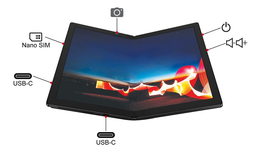
Overview
Camera with infrared (IR) function Power button
Volume button USB-C™ connector (USB 3.2 Gen 2)
Nano-SIM-card tray *
* for selected models
Locating FRUs and CRUs
This topic introduces the following service parts:
• “Major FRUs and CRUs” on page 34
• “Other parts” on page 36
© Copyright Lenovo 2020, 2021 33Notes:
• FRUs refer to parts that must be installed or replaced only by trained service technicians. If customers choose to
replace the FRUs by themselves, the product warranty might be affected.
• Each FRU is available for all types or models, unless otherwise specified.
• CRU statement for customers:
You can resolve some problems with your product with a replacement part you can install yourself, called a
“Customer Replaceable Unit” or “CRU.” Some CRUs are designated as self-service CRUs and others are
designated as optional-service CRUs. Installation of self-service CRUs is your responsibility. For optional-service
CRUs, you can either install the CRU yourself or you can request that a Service Provider install the CRU according to
the warranty service for your product. If you intend on installing the CRU, Lenovo will ship the CRU to you. CRU
information and replacement instructions are shipped with your product and are available from Lenovo at any time
upon request. You can find a list of CRUs for your product in this Hardware Maintenance Manual. An electronic
version of this manual can be found at https://support.lenovo.com. Tap Documentation and then follow the on-
screen instructions to find the manual for your product. You might be required to return the defective part that is
replaced by the CRU. When return is required: (1) return instructions, a prepaid shipping label, and a container will
be included with the replacement CRU; and (2) you might be charged for the replacement CRU if Lenovo does not
receive the defective CRU within thirty (30) days of your receipt of the replacement CRU. See your Lenovo Limited
Warranty documentation for full details.
ThinkPad computers contain the following types of CRUs:
Self-service CRUs: Refer to parts that can be installed or replaced easily by customer themselves or by trained
service technicians at an additional cost.
Optional-service CRUs: Refer to parts that can be installed or replaced by customers with a greater skill level.
Trained service technicians can also provide service to install or replace the parts under the type of warranty
designated for the customer’s machine.
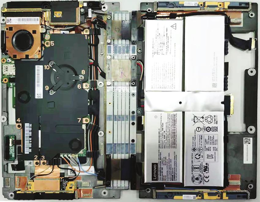
Major FRUs and CRUs
Notes:
• Depending on the computer model, your computer might look different from the illustration.
• The Lenovo factory recovery USB key d is used to restore the Microsoft Windows operating system. It
might not come with the computer, and a user might order it from https://pcsupport.lenovo.com/
lenovorecovery, though additional shipping and handling fees might apply.
34 Hardware Maintenance ManualNo. FRU Self-service CRU Optional-service CRU
1 Folio cover set No No
2 Nano-SIM-card cap * No No
3 Nano-SIM-card tray * Yes No
4 System board assembly No No
5 Access door No No
6 Thermal sub-spreader No No
7 Wireless WAN card * No No
8 Thermal pad for wireless WAN card No No
9 M.2 solid-state drive No No
10 Thermal pad for M.2 solid-state drive No No
11 OLED assembly with frame cover and miscellaneous No No
parts
12 USB-C sub cards No No
Chapter 5. Locations 35No. FRU Self-service CRU Optional-service CRU 13 USB-C sub card cable No No 14 Support bracket No No 15 Smart glass No No a Power cord Yes No b ac power adapter Yes No c Miscellaneous parts kits No No d Lenovo factory recovery USB key * Yes No * for selected models Other parts Table 2. Other parts Descriptions Self-service CRU Optional-service CRU Lenovo USB-C to Ethernet Adapter * Yes No Lenovo Pen Pro * Yes No Lenovo Mod Pen * Yes No Lenovo Fold Mini Keyboard * Yes No Lenovo Powered USB-C Travel Hub * Yes No * for selected models Looking up FRU information For detailed FRU information, including part numbers, descriptions, and substitution part numbers, go to https://support.lenovo.com/partslookup. 36 Hardware Maintenance Manual
Chapter 6. FRU replacement notices
This chapter presents notices related to removing and replacing parts. Read this chapter carefully before
replacing any FRU.

CRU statement for customers:
You can resolve some problems with your product with a replacement part you can install yourself, called a
“Customer Replaceable Unit” or “CRU.” Some CRUs are designated as self-service CRUs and others are
designated as optional-service CRUs. Installation of self-service CRUs is your responsibility. For optional-
service CRUs, you can either install the CRU yourself or you can request that a Service Provider install the
CRU according to the warranty service for your product. If you intend on installing the CRU, Lenovo will ship
the CRU to you. CRU information and replacement instructions are shipped with your product and are
available from Lenovo at any time upon request. You can find a list of CRUs for your product in this Hardware
Maintenance Manual. An electronic version of this manual can be found at https://support.lenovo.com. Tap
Guides & Manuals and then follow the on-screen instructions to find the manual for your product. You might
be required to return the defective part that is replaced by the CRU. When return is required: (1) return
instructions, a prepaid shipping label, and a container will be included with the replacement CRU; and (2) you
might be charged for the replacement CRU if Lenovo does not receive the defective CRU within thirty (30)
days of your receipt of the replacement CRU. See your Lenovo Limited Warranty documentation for full
details.

Service tool kit
Ensure that the following service tool kit is prepared before you service a ThinkPad notebook computer.

 No.      Tool name                                         Tool type

 1        Phillips-head screwdriver                         Common tool

 2        Torx-head screwdriver                             Common tool
 3        Conductive tweezers                               Common tool
 4        Hexagonal socket                                  Common tool

 5        Silicone grease                                   Consumable tool

 6        Polyamide tape                                    Consumable tool
 7        Mylar tape                                        Consumable tool

 8        Eraser                                            Consumable tool
 9        Electrical tape                                   Consumable tool

 10       Double-sided tape                                 Consumable tool

 11       Conductive tape                                   Consumable tool

Note: The silicone grease can be applied to the surfaces of the microprocessor and heatsink to eliminate air
gaps. The hexagonal socket is used to pick up the antenna connectors.

Screw notices
Loose screws can cause a reliability problem. In the ThinkPad computer, this problem is addressed with
special nylon-coated screws that have the following characteristics:

© Copyright Lenovo 2020, 2021                                                                               37
• They maintain tight connections.
• They do not easily come loose, even with shock or vibration.
• They are harder to tighten.

Do the following when you service this machine:
• Keep the screw kit in your tool bag. For the part number of the screw kit, go to https://support.lenovo.com/
  partslookup.

Tighten screws as follows:
• Plastic to plastic
  Turn an additional 90 degrees after the screw head touches the surface of the plastic part.

• Logic card to plastic
  Turn an additional 180 degrees after the screw head touches the surface of the logic card.

Notes:
• Ensure that you use the correct screw. It is recommended to use new screws for replacements. If you
  have a torque screwdriver, tighten all screws firmly to the torque specified in the screw information table
  for each step.
• Ensure that torque screwdrivers are calibrated correctly following country specifications.

Retaining serial numbers
Instructions for retaining serial numbers, MTM, UUID, or asset ID can be found from the Lenovo Support
Web site at:
https://support.lenovo.com

38   Hardware Maintenance Manual
Chapter 7. Removing or replacing a FRU
This chapter provides instructions on how to remove or replace a FRU.

CRU statement for customers:

You can resolve some problems with your product with a replacement part you can install yourself, called a
“Customer Replaceable Unit” or “CRU.” Some CRUs are designated as self-service CRUs and others are
designated as optional-service CRUs. Installation of self-service CRUs is your responsibility. For optional-
service CRUs, you can either install the CRU yourself or you can request that a Service Provider install the
CRU according to the warranty service for your product. If you intend on installing the CRU, Lenovo will ship
the CRU to you. CRU information and replacement instructions are shipped with your product and are
available from Lenovo at any time upon request. You can find a list of CRUs for your product in this Hardware
Maintenance Manual. An electronic version of this manual is available for downloading at https://
support.lenovo.com. You might be required to return the defective CRU. When return is required: (1) return
instructions, a prepaid shipping label, and a container will be included with the replacement CRU; and (2) you
might be charged for the replacement CRU if Lenovo does not receive the defective part within thirty (30)
days of your receipt of the replacement CRU. See your Lenovo Limited Warranty documentation for full
details.

General guidelines
When removing or replacing a FRU, be sure to observe the following general guidelines:
 1. Do not try to service any computer unless you have been trained and certified. An untrained person runs
    the risk of damaging parts.
 2. Before replacing any FRU, review Chapter 6 “FRU replacement notices” on page 37.
 3. Begin by removing any FRUs that have to be removed before replacing the failing FRU. Any such FRUs
    are listed at the beginning of in each FRU replacement section. Remove them in the order in which they
    are listed.
 4. Follow the correct sequence in the steps for removing a FRU, as given in the drawings by the numbers in
    square callouts.
 5. When turning a screw, turn it in the direction as given by the arrow in the drawing.
 6. When removing a FRU, remove it in the direction as given by the arrow in the drawing.
 7. To put the new FRU in place, reverse the removal procedure and follow any notes that pertain to
    replacement.
 8. When replacing a FRU, use the correct screws as shown in the replacement procedures.

     DANGER

 Before removing any FRU, turn off the computer, unplug all power cords from electrical outlets, and
 then disconnect any interconnecting cables.

Attention: After replacing a FRU, do not turn on the computer until you have made sure that all screws,
springs, and other small parts are in place and none are loose inside the computer. Verify this by shaking the
computer gently and listening for rattling sounds. Metallic parts or metal flakes can cause electrical short
circuits.

Attention: The system board is sensitive to, and can be damaged by, electrostatic discharge(ESD). Before
touching it, establish personal grounding by touching a ground point with one hand or by using an ESD strap.

© Copyright Lenovo 2020, 2021                                                                               39
Before servicing the computer
Before you service this computer, do the following:
1. Disable the built-in battery. See “Disabling the built-in battery” on page 40.
2. Remove the nano-SIM-card tray. See “Removing the Nano-SIM-card tray” on page 40.
Disabling the built-in battery
Before replacing any FRU, ensure that you disable Fast Startup first and then disable the built-in battery.
To disable Fast Startup, do the following:
1. Go to Control Panel, and then change the view of Control Panel from Category to Large icons or Small
icons.
2. Click Power Options, and then click Choose what the power buttons do on the left pane.
3. Click Change settings that are currently unavailable at the top.
4. If prompted by User Account Control (UAC), click Yes.
5. Clear the Turn on fast startup check box, and then click Save changes.
To disable the built-in battery, do the following:
1. Restart the computer. When the logo screen is displayed, tap the prompt to display the Startup Interrupt
Menu window. In the Startup Interrupt Menu window, tap F1 to enter the UEFI BIOS menu.
2. Select Config ➙ Power. The Power submenu is displayed.
3. Tap Disable Built-in Battery.
4. Select Yes in the Setup Confirmation window. The built-in battery is disabled and the computer turns off
automatically. Wait three to five minutes to let the computer cool.
Removing the Nano-SIM-card tray
Remove the following items before you service the computer:
• Nano-SIM-card tray*
40 Hardware Maintenance ManualRemoval steps of the Nano-SIM-card tray
* for selected models
1010 Folio cover set
Note: The computer you are servicing might look slightly different from the following illustrations.
Before you replace the folio cover set, do the following:
1. Disable the built-in battery. See “Disabling the built-in battery” on page 40.
2. Remove the Nano-SIM-card tray. See “Removing the Nano-SIM-card tray” on page 40.
Removal steps of the folio cover set
Before releasing the adhesive tapes, put a plastic plate between the folio cover set and system board
assembly as shown in step 2 to protect both folio cover set and system board assembly. In step 3 and step
4 , use a tweezer to grab the tapes, then roll the tweezer and pull out the tapes as shown.
Chapter 7. Removing or replacing a FRU 414a
4b
3a
3b
Note: After removing all the screws in step 6 , use a spudger or a pry tool to push the two slider brackets as
shown in step 7 .
Step Screw (quantity) Color Torque
6 M2 × L3 mm, flat-head, nylon-coated (4) Silver 0.181 Nm
(1.85 kgf-cm)
42 Hardware Maintenance ManualStep Screw (quantity) Color Torque
8 M2.0 × L1.9 mm, flat-head, nylon-coated (8) Pink 0.137 Nm
(1.4 kgf-cm)
Installation steps of the folio cover set
Step Screw (quantity) Color Torque
2 M2.0 × L1.9 mm, flat-head, nylon-coated (8) Pink 0.137 Nm
(1.4 kgf-cm)
Put the folio cover as shown in step 3 , ensure that there is a 5 mm to 10 mm distance between the edge of
the folio cover and the computer edge.
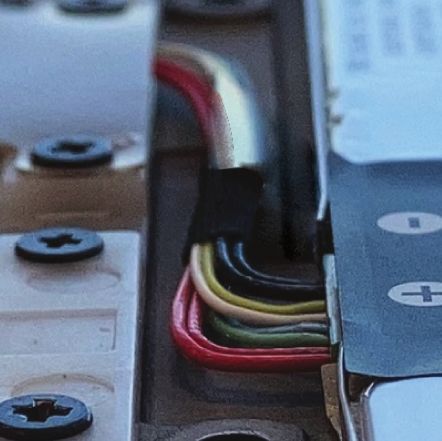
Chapter 7. Removing or replacing a FRU 435~
10
mm
Put the folio cover on the system board assembly and slide the folio cover as shown in step 4 until the hooks
on the bottom of the folio cover are latched correctly.
Step Screw (quantity) Color Torque
6 M2 × L3 mm, flat-head, nylon-coated (4) Silver 0.181 Nm
(1.85 kgf-cm)
44 Hardware Maintenance ManualEnsure that the folio cover is aligned properly in step 8 .
1020 Smart glass and adhesive tapes
Before you replace the speaker assembly, do the following:
1. Disable the built-in battery. See “Disabling the built-in battery” on page 40.
2. Remove the Nano-SIM-card tray. See “Removing the Nano-SIM-card tray” on page 40.
3. Remove the folio cover set. See “1010 Folio cover set” on page 41.
Chapter 7. Removing or replacing a FRU 45Removal steps of the smart glass and adhesive tapes When installing: Ensure that the adhesive taps are attached firmly. 46 Hardware Maintenance Manual
1030 Access door
Before you replace the access door, do the following:
 1. Disable the built-in battery. See “Disabling the built-in battery” on page 40.
 2. Remove the Nano-SIM-card tray. See “Removing the Nano-SIM-card tray” on page 40.
 3. Remove the following FRUs:
     •   “1010 Folio cover set” on page 41

Removal steps of the access door

 Step         Screw (quantity)                                       Color              Torque
 1            M2 × L3.5 mm, flat-head, nylon-coated (2)              Black              0.181 Nm
                                                                                        (1.85 kgf-cm)

1040 Support bracket
Before you replace the support bracket, do the following:
 1. Disable the built-in battery. See “Disabling the built-in battery” on page 40.
 2. Remove the Nano-SIM-card tray. See “Removing the Nano-SIM-card tray” on page 40.
 3. Remove the following FRUs:
     •   “1010 Folio cover set” on page 41
     •   “1020 Smart glass and adhesive tapes” on page 45

                                                                         Chapter 7. Removing or replacing a FRU   47
Removal steps of the support bracket
Step Screw (quantity) Color Torque
1 M2 × L3.5 mm, flat-head, nylon-coated (1) Black 0.181 Nm
(1.85 kgf-cm)
When installing: Ensure that the support bracket is installed correctly.
1050 System board assembly
Before you replace the system board assembly, do the following:
1. Disable the built-in battery. See “Disabling the built-in battery” on page 40.
2. Remove the Nano-SIM-card tray. See “Removing the Nano-SIM-card tray” on page 40.
3. Remove the following FRUs:
• “1010 Folio cover set” on page 41
48 Hardware Maintenance ManualYou can also read