HDS Live Installation Manual - www.lowrance.com
←
→
Page content transcription
If your browser does not render page correctly, please read the page content below
HDS Live
Installation Manual
ENGLISH

          www.lowrance.com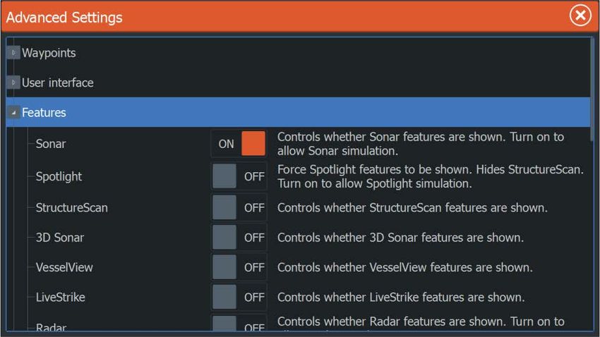
Preface

Disclaimer
As Navico is continuously improving this product, we retain the
right to make changes to the product at any time which may not be
reflected in this version of the manual. Please contact your nearest
distributor if you require any further assistance.
It is the owner’s sole responsibility to install and use the equipment
in a manner that will not cause accidents, personal injury or
property damage. The user of this product is solely responsible for
observing maritime safety practices.
NAVICO HOLDING AS AND ITS SUBSIDIARIES, BRANCHES AND
AFFILIATES DISCLAIM ALL LIABILITY FOR ANY USE OF THIS PRODUCT
IN A WAY THAT MAY CAUSE ACCIDENTS, DAMAGE OR THAT MAY
VIOLATE THE LAW.
This manual represents the product as at the time of printing.
Navico Holding AS and its subsidiaries, branches and affiliates
reserve the right to make changes to specifications without notice.
Governing language
This statement, any instruction manuals, user guides and other
information relating to the product (Documentation) may be
translated to, or has been translated from, another language
(Translation). In the event of any conflict between any Translation of
the Documentation, the English language version of the
Documentation will be the official version of the Documentation.

Copyright
Copyright © 2018 Navico Holding AS.

Warranty
The warranty card is supplied as a separate document. In case of any
queries, refer to the brand website of your unit or system:
www.lowrance.com

Preface | HDS Live Installation Manual                                   3
Compliance statements
    Europe
    Navico declare under our sole responsibility that the product
    conforms with the requirements of:
    • CE under RED 2014/53/EU
    The relevant declaration of conformity is available in the product's
    section at the following website:
    • www.lowrance.com

    Countries of intended use in the EU

     AT - Austria                            LI - Liechtenstein
     BE - Belgium                            LT - Lithuania
     BG - Bulgaria                           LU - Luxembourg
     CY - Cyprus                             MT - Malta
     CZ - Czech Republic                     NL - Netherlands
     DK - Denmark                            NO - Norway
     EE - Estonia                            PL - Poland
     FI - Finland                            PT - Portugal
     FR - France                             RO - Romania
     DE - Germany                            SK - Slovak Republic
     GR - Greece                             SI - Slovenia
     HU - Hungary                            ES - Spain
     IS - Iceland                            SE - Sweden
     IE - Ireland                            CH - Switzerland
     IT - Italy                              TR - Turkey
     LV - Latvia                             UK - United Kingdom

    United States of America
    Navico declare under our sole responsibility that the product
    conforms with the requirements of:
    • Part 15 of the FCC Rules. Operation is subject to the following
      two conditions: (1) this device may not cause harmful
      interference, and (2) this device must accept any interference
      received, including interference that may cause undesired
      operation

4   Preface | HDS Live Installation Manual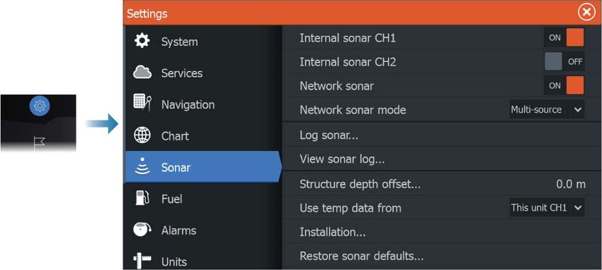
Warning: The user is cautioned that any changes or
  modifications not expressly approved by the party
  responsible for compliance could void the user’s
  authority to operate the equipment.

Ú Note: This equipment generates, uses and can radiate radio
  frequency energy and, if not installed and used in accordance
  with the instructions, may cause harmful interference to radio
  communications. However, there is no guarantee that the
  interference will not occur in a particular installation. If this
  equipment does cause harmful interference to radio or
  television reception, which can be determined by turning the
  equipment off and on, the user is encouraged to try to correct
  the interference by one or more of the following measures:
• Reorient or relocate the receiving antenna
• Increase the separation between the equipment and receiver
• Connect the equipment into an outlet on a circuit different from
  that of the receiver is connected
• Consult the dealer or an experienced technician for help

Industry Canada
This device complies with Industry Canada’s license-exempt RSSs.
Operation is subject to the following two conditions: (1) This device
may not cause interference; and (2) This device must accept any
interference, including interference that may cause undesired
operation of the device.
Le présent appareil est conforme aux CNR d’Industrie Canada
applicables aux appareils radio exempts de licence. L’exploitation
est autorisée aux deux conditions suivantes: (1) l’appareil ne doit pas
produire de brouillage, et. (2) l’utilisateur de l’appareil doit accepter
tout brouillage radioélectrique subi, même si le brouillage est
susceptible d’en compromettre le fonctionnemen.
Industry Canada Statement: Under Industry Canada regulations, this
radio transmitter may only operate using an antenna of a type and
maximum (or lesser) gain approved for the transmitter by Industry
Canada. To reduce potential radio interference to other users, the
antenna type and its gain should be so chosen that the equivalent
isotropically radiated power (e.i.r.p.) is not more than that necessary
for successful communication.

Preface | HDS Live Installation Manual                                      5
Conformément à la réglementation d’Industrie Canada, le présent
    émetteur radio peut fonctionner avec une antenne d’un type et
    d’un gain maximal (ou inférieur) approuvé pour l’émetteur par
    Industrie Canada. Dans le but de réduire les risques de brouillage
    radioélectrique à l’intention des autres utilisateurs, il faut choisir le
    type d’antenne et son gain de sorte que la puissance isotrope
    rayonnée quivalente (p.i.r.e.) ne dépassepas l’intensité nécessaire à
    l’établissement d’une communication satisfaisante.

    Australia and New Zealand
    Navico declare under our sole responsibility that the product
    conforms with the requirements of:
    • level 2 devices of the Radiocommunications (Electromagnetic
      Compatibility) standard 2017
    • radiocommunications (Short Range Devices) Standards 2014

    Internet usage
    Some features in this product use an internet connection to
    perform data downloads and uploads. Internet usage via a
    connected mobile/cell phone internet connection or a pay-per-MB
    type internet connection may require large data usage. Your service
    provider may charge you based on the amount of data you transfer.
    If you are unsure, contact your service provider to confirm rates and
    restrictions.

    Trademarks
    Navico® is a registered trademark of Navico Holding AS.
    Lowrance® is a registered trademark of Navico Holding AS.
    Bluetooth® is a registered trademark of Bluetooth SIG, Inc.
    CZone™ is a trademark of Power Products LLC.
    Evinrude® is a registered trademark of BRP US, Inc.
    HDMI® and HDMI™, the HDMI Logo, and High-Definition Multimedia
    Interface are trademarks or registered trademarks of HDMI Licensing
    LLC in the United States and other countries.
    Mercury® is a registered trademark of Mercury.
    NMEA® and NMEA 2000® are registered trademarks of the National
    Marine Electronics Association.

6   Preface | HDS Live Installation Manual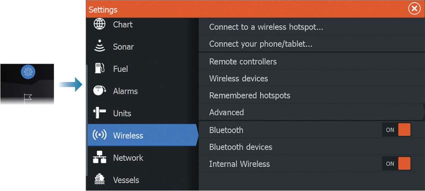
Power-Pole® is a registered trademark of JL Marine Systems, Inc.
SD™ and microSD™ are trademarks or registered trademarks of
SD-3C, LLC in the United States, other countries or both.
SmartCraft VesselView® is a registered trademark of Mercury.
Suzuki® is a registered trademark of Suzuki.
Yamaha® is a registered trademark of Yamaha.

About this manual
This manual is a reference guide for installing units.
Some features may not be activated or available for screenshots in
the manual. As a result, screenshots of menus and dialogs may not
match the look of your unit.
Important text that requires special attention from the reader is
emphasized as follows:
Ú Note: Used to draw the reader’s attention to a comment or
  some important information.

    Warning: Used when it is necessary to warn
  personnel that they should proceed carefully to
  prevent risk of injury and/or damage to equipment/
  personnel.

Preface | HDS Live Installation Manual                               7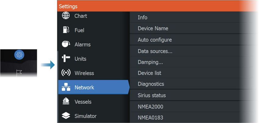
8 Preface | HDS Live Installation Manual
Contents
11 Introduction
11   Parts included
12   Keys
14   Card reader
15   Connectors

16 Installation
16   Installation guidelines
17   U-bracket mounting
17   Panel mounting

18 Wiring
18   Connectors
18   Wiring guidelines
19   Power, NMEA 0183 and video input
22   USB devices
23   NMEA 2000
25   Ethernet device connection
26   HDMI input
27   Sonar CH1 - blue 9-pin connector
27   Sonar CH2 - black 9-pin connector

28 Software setup
28   First time startup
28   Software setup sequence
28   Turning the system on and off
28   The settings dialog
29   System settings
30   Alarms
31   Radar settings
36   Sonar settings
40   Autopilot settings
45   Fuel settings
47   Wireless settings
48   Network settings

52 3rd party support
52   SmartCraft VesselView integration

     Contents | HDS Live Installation Manual   9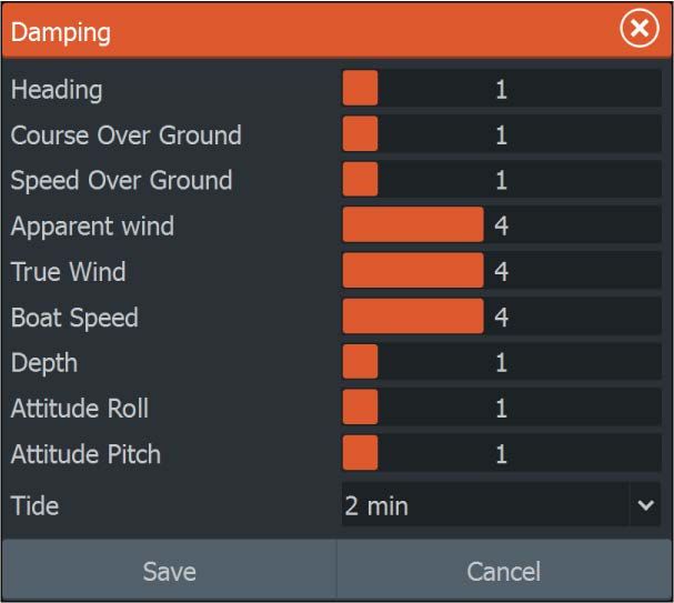
52   Suzuki engine integration
     52   Yamaha engine integration
     53   Evinrude engine integration
     53   Power-Pole anchors
     53   C-Zone

     56 Accessories

     57 Supported data
     57   NMEA 2000 compliant PGN List
     61   NMEA 0183 supported sentences

     63 Technical specifications
     63   HDS Live

     66 Dimensional drawings
     66   7" unit
     66   9" unit
     67   12" unit
     67   16" unit

10        Contents | HDS Live Installation Manual
1
Introduction
Parts included
HDS Live
A B1 B2
C
D E F
A HDS Live unit
B1 U-bracket kit (plastic), HDS-7 Live and HDS-9 Live
B2 U-bracket kit (metal), HDS-12 Live and HDS-16 Live
C Sun cover
D Power cable kit
E Gasket
F Documentation pack
Introduction | HDS Live Installation Manual 11Keys
The front panel keys
A B
C
D MOB
E
F
G H
I
A Pages key
• Press once to activate the Home page. Repeat short
presses to cycle the favorite buttons
• Press and hold is configurable. Refer to the operator
manual for details
B Waypoint key
• Press to open the new waypoint dialog
• Press twice to save a waypoint
• Press and hold to access the find dialog
C Arrow keys
• Press arrows to move through menu items, to adjust a
value, and to move the cursor on a panel
D Exit (X) key
• Press to exit a dialog, to return to previous menu level, to
remove the cursor from the panel or to restore the cursor
on the panel
12 Introduction | HDS Live Installation ManualE Enter key
• Press to select or save your settings
F Zoom keys and MOB key
• Zoom keys for panels and images
• Simultaneous pressing both keys saves a Man Overboard
(MOB) waypoint at the current vessel position
G Menu key
• Press to display the menu for the active panel/overlay
• Press twice to display the settings dialog
• Press and hold to hide or show the menu
H Power key
• Press to turn the unit ON
• Press and hold to turn the unit OFF
• When ON, press once to display the System Controls
dialog. Repeat short presses to cycle the backlight
brightness
I Quick access keys (HDS-12 Live and HDS-16 Live units
only)
• For configuration of the quick access keys refer to the
operator manual.
Introduction | HDS Live Installation Manual 13Card reader
A memory card can be used for:
• Chart data
• Software updates
• Transfer of user data
• System backup
Ú Note: Do not download, transfer or copy files to a chart card.
Doing so can damage chart information on the chart card.
The protective door should always be securely shut immediately
after inserting or removing a card, in order to prevent possible water
ingress.
14 Introduction | HDS Live Installation ManualConnectors
HDS Live
7" unit
E D A B C
9" unit
E D D A B C
12" and 16" unit
E D D F G A B C
A Power, video input and NMEA 0183 connector
B Sonar CH1 - blue 9-pin connector
C Sonar CH2 - black 9-pin connector
D Ethernet connector (5-pin)
E NMEA 2000 connector
F HDMI output connector
G USB connector
Introduction | HDS Live Installation Manual 152
Installation
Installation guidelines
Choose the mounting location carefully, make sure that there are no
hidden electrical wires or other parts behind the panel before you
drill or cut. Ensure that any holes cut are in a safe position and will
not weaken the boat’s structure. If in doubt, consult a qualified boat
builder, or marine electronics installer.
Don´t:
• Mount any part where it can be used as a hand hold
• Mount any part where it might be submerged
• Mount any part where it will interfere with the operation,
launching, or retrieving of the boat
Do:
• Test the unit in its intended location to ensure satisfactory
wireless and GPS performance. Metal and carbon materials are
known to impact the performance in a negative way. A well
placed external GPS source and/or wireless module can be
added to overcome poor performance
• Consider the optimum viewing angles
• Consider the overall width and height requirements
• Consider access to the card reader
• Leave sufficient clearance to connect all relevant cables
• Check that it is possible to route cables to the intended
mounting location
Ú Note: Where flush mounted, the enclosure should be dry and
well ventilated. In small enclosures, it may be required to fit
forced cooling.
Warning: Inadequate ventilation and subsequent
overheating of the unit may cause unreliable operation
and reduced service life. Exposing the unit to
conditions that exceeds the specifications could
invalidate your warranty. Refer to the technical
specifications in the "Technical specifications" on page 63.
16 Installation | HDS Live Installation ManualU-bracket mounting
1. Place the bracket in the desired mounting location. Ensure that
the chosen location has enough height to accommodate the
unit fitted in the bracket, and allows tilting of the unit. Also
adequate space is required on both sides to allow tightening
and loosening of the knobs.
2. Mark the screw locations using the bracket as a template, and
drill pilot holes. Use fasteners suited to the mounting surface
material.
3. Screw down the bracket.
4. Mount the unit to the bracket using the knobs. Hand tighten
only.
3 4
Panel mounting
Refer to the separate mounting template for panel mounting
instructions.
Installation | HDS Live Installation Manual 173
Wiring
Connectors
Different models have different connectors. For available
connectors and connector layout refer to "Connectors" on page 15.
Wiring guidelines
Don't:
• Make sharp bends in the cables
• Run cables in a way that allows water to flow down into the
connectors
• Run the data cables adjacent to radar, transmitter, or large/high
current carrying cables or high frequency signal cables.
• Run cables so they interfere with mechanical systems
• Run cables over sharp edges or burrs
Do:
• Make drip and service loops
• Use cable-tie on all cables to keep them secure
• Solder/crimp and insulate all wiring connections if extending or
shortening the cables. Extending cables should be done with
suitable crimp connectors or solder and heat shrink. Keep joins as
high as possible to minimize possibility of water immersion.
• Leave room adjacent to connectors to ease plugging and
unplugging of cables
Warning: Before starting the installation, be sure to
turn electrical power off. If power is left on or turned on
during the installation, fire, electrical shock, or other
serious injury may occur. Be sure that the voltage of the
power supply is compatible with the unit.
Warning: The positive supply wire (red) should
always be connected to (+) DC with a fuse or a circuit
breaker (closest available to fuse rating).
18 Wiring | HDS Live Installation ManualPower, NMEA 0183 and video input
Connector details
7 10
8 6
9
5
1
2 4
3
Unit socket (female)
Pin Purpose
1 Accessory wake up
2 Listener B (Rx_B)
3 Video in +
4 Talker B (Tx_B)
5 Drain
6 Talker A (Tx_A)
7 + 12 V DC
8 DC negative
9 Video in -
10 Listener A (Rx_A)
Ú Note: To use the video input functionality, an adapter cable has
to be used (sold separately).
Power
The unit is designed to be powered by 12 V DC.
It is protected against reverse polarity, under voltage and over
voltage (for a limited duration).
Wiring | HDS Live Installation Manual 19A fuse or circuit breaker should be fitted to the positive supply. For
recommended fuse rating, refer to "Technical specifications" on page 63.
NMEA 0183
The unit has a built in NMEA 0183 serial interface, providing both
input and output. The port(s) uses the NMEA 0183 (serial balanced)
standard, and can be configured in the software for different baud
rates up to 38,400 baud.
Talkers and listeners
Only one talker (output device) can be connected to a serial input
(RX) on the unit, in accordance with the NMEA0183 protocol.
However, an output port (TX) on the unit may be connected to up
to three listener (receiver) devices, dependent on the hardware
capabilities of the receiver.
Video input
The unit can be connected to a composite video source, and display
video images on its display.
Ú Note: Camera cables are not supplied, and will need to be
selected to suit termination - RCA at the unit, and typically BNC
or RCA plug at the camera end.
Ú Note: The video images will not be shared with another unit via
the network. It is only possible to view video on the unit
connected to the video source.
Ú Note: Both NTSC and PAL formats are supported.
Video input configuration
Configurations to video input are made in the video panel, refer to
the Operator Manual for more information.
20 Wiring | HDS Live Installation ManualPower and NMEA 0183 cable
A B D
C
E
F
G
H
I
Key Description Color
A + 12 V DC Red
B DC negative Black
C Fuse --
D Accessory wake up Yellow
E Talker A (Tx_A) Yellow
F Talker B (Tx_B) Blue
G Listener A (Rx_A) Orange
H Listener B (Rx_B) Green
I Ground (shield) --
Accessory wake up
The accessory wake up wire may be used to control the power state
of external equipment. Combine all accessory wake up wires on a
common bus or to a single termination point. When connected in
this manner, the connected equipment will turn on the moment
the unit is powered up.
Wiring | HDS Live Installation Manual 21A
B
A
Key Purpose Color
A Accessory wake up wire Yellow
B Accessory wake up line
Video adapter cable (sold separately)
A
B
C
Key Description
A Video adapter cable (Connects to the unit socket)
B BNC connector (female)
C Power and NMEA 0183 cable
USB devices
The USB port(s) can be used to:
22 Wiring | HDS Live Installation Manual• Connect a storage device for software updates, transfer of user
data, and for system backup
• Charge a connected device. For maximum output power refer to
the "Technical specifications" on page 63
Ú Note: USB cable length should not exceed 5 m when using
regular cables. Lengths over 5 m may be possible with the use
of an active USB cable.
USB connector details
Unit socket (female) Cable plug/Device plug (male)
The unit is equipped with standard USB type-A connector(s).
NMEA 2000
The NMEA 2000 data port allows receiving and sharing of a
multitude of data from various sources.
Connector details
1
5
2 4
3
Unit socket (male)
Pin Purpose
1 Shield
2 NET-S (+12 V DC)
3 NET-C (DC negative)
4 NET-H
Wiring | HDS Live Installation Manual 23Pin Purpose
5 NET-L
Plan and install an NMEA 2000 network
An NMEA 2000 network consists of a powered backbone from
which drop cables connect to NMEA 2000 devices. The backbone
needs to run within 6 m (20 ft) of the locations of all products to be
connected, typically in a bow to stern layout.
The following guidelines apply:
• The total length of the backbone should not exceed 100 meters
(328 ft)
• A single drop cable has a maximum length of 6 meters (20 ft).
The total length of all drop cables combined should not exceed
78 meters (256 ft)
• The backbone needs to have a terminator at each end of the
backbone. The terminator can be a terminator plug or a unit with
built-in terminator
A A A
B B B
C C
D
E
A NMEA 2000 device
B Drop-cable
C Terminator
D Power supply
E Backbone
Powering the network
The network requires its own 12 V DC power supply, protected by a
3 amp fuse.
For smaller systems: connect power at any location in the backbone.
For larger systems: connect power at a central point in the
backbone to balance the voltage drop of the network. Make the
24 Wiring | HDS Live Installation Manualinstallation such that the load/current draw on each side of the
power node is equal.
Ú Note: 1 LEN (Load Equivalency Number) equals 50 mA current
draw.
Ú Note: Do not connect the NMEA 2000 power cable to the same
terminals as the engine start batteries, autopilot computer, bow
thruster or other high current devices.
Ethernet device connection
Connection of network devices can be made directly to the
Ethernet port, or via a network expansion device to the Ethernet
port.
Ethernet connector details
4
5 3
2
1
Unit socket (female)
Pin Purpose
1 Transmit positive TX+
2 Transmit negative TX-
Wiring | HDS Live Installation Manual 25Pin Purpose
3 Receive positive RX+
4 Receive negative RX-
5 Shield
Ethernet devices
The Ethernet ports can be used for transfer of data and
synchronization of user created data. It is recommended that each
MFD in the system is connected to the Ethernet network.
No special setup is required for establishing an Ethernet network, it
is all plug-and-play.
Ethernet expansion device
Connection of network devices can be made via an Ethernet
expansion device. Additional expansion devices can be added to
provide the required number of ports.
HDMI input
The unit can be connected to an external video source to display
video images on its display.
HDMI connector details
Unit socket (female) Cable plug (male)
The unit is equipped with standard HDMI (Type A) connector(s). The
unit should be turned off prior to connecting or disconnecting an
HDMI cable.
Ú Note: While the HDMI standard does not state maximum cable
length, signal may be compromised on long runs. Only use
Navico or other high quality HDMI certified cables. 3rd party
cables should be tested before installation. On runs over 10 m it
may be required to add an HDMI amplifier or use HDMI-CAT6
adaptors.
26 Wiring | HDS Live Installation ManualVideo input configuration Configurations to video input are made in the video panel, refer to the Operator Manual for more information. Sonar CH1 - blue 9-pin connector Supports: • Sonar / CHIRP Sonar • DownScan • Active Imaging 3D transducer • LiveSight Down/Forward transducer Ú Note: A 7-pin transducer cable can be connected to a 9-pin port using a 7-pin to 9-pin adaptor cable. However, if the transducer has a paddle wheel speed sensor, the water-speed data will not be displayed on the unit. Ú Note: Channel 1 can do SideScan via an Active Imaging 3D transducer. It cannot do SideScan from an Active Imaging, Active Imaging 3-in-1, TotalSCan, StructureScan or StructureScan HD transducer. Sonar CH2 - black 9-pin connector Supports: • Sonar / CHIRP Sonar • DownScan • SideScan • Active Imaging/Active imaging 3-in-1/TotalScan/StructureScan Ú Note: A 7-pin transducer cable can be connected to a 9-pin port using a 7-pin to 9-pin adaptor cable. However, if the transducer has a paddle wheel speed sensor, the water-speed data will not be displayed on the unit. Wiring | HDS Live Installation Manual 27
4
Software setup
First time startup
When the unit is started for the first time, or after a factory default,
the unit displays a series of dialogs. Respond to the dialog prompts
to make fundamental settings.
You can perform further setup and later change settings using the
system settings dialogs.
Software setup sequence
1 General settings - refer to "System settings" on page 29.
• Make general settings as desired
2 Advanced settings - refer to "Advanced" on page 29.
• Enable or disable features
• Review the advanced setting options and make changes
as desired
3 Source selection - refer to "Network settings" on page 48.
• Make sure that the proper external data sources have
been selected
4 Feature setup
• Configure specific features as described later in this
chapter
Turning the system on and off
The system is turned on by pressing the Power key.
Press and hold the Power key to turn the unit off.
You can also turn the unit off from the System Controls dialog.
If the Power key is released before the shut-down is completed, the
power off process is cancelled.
The settings dialog
The software setup is done from the settings dialog.
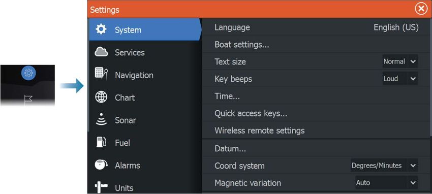
28 Software setup | HDS Live Installation ManualSystem settings Boat settings Used to specify the physical attributes of the boat. Time Controls the local time zone offset, and the format of the time and date. Advanced Used for configuration of advanced settings and how your system displays various user interface information. Enabling or disabling features Use the feature option to enable or disable features that are not automatically enabled or disabled by the system. Software setup | HDS Live Installation Manual 29
Alarms
Settings
List of all available alarm options in the system, with current
settings.
From this list you can activate, deactivate and change alarm limits.
Siren enable
The Siren enabled option must be set in order for the unit to
activate the buzzer when an alarm condition arises.
Its setting also determines the operation of the external alarm
output.
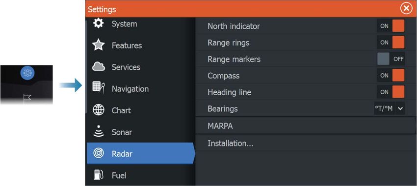
30 Software setup | HDS Live Installation ManualRadar settings Installation settings The radar system requires radar sensor specific setting in order to adjust for a number of variables found in different installations. Ú Note: The installation settings available depends on the radar sensor. Radar source In a system with more than one radar sensor, the device to configure is selected from this menu. Ú Note: Radars that support dual radar mode are represented twice in the source list, with an A and B suffix. Software setup | HDS Live Installation Manual 31
Radar status
     Displays scanner information and scanner features, primarily used
     for information and to assist with fault finding.

     Adjust antenna height
     Set the radar scanner height relative to the water surface. The Radar
     uses this value to calculate the correct STC settings.

     Select antenna length
     Select the proper antenna length.

     Adjust range offset
     The radar sweep should commence at your vessel (a radar range of
     zero). You may need to adjust the radar range offset to achieve this.
     If this is set incorrectly, a large dark circle in the center of the sweep
     might occur. You might notice straight objects such as straight sea
     walls or piers having curves or an indentation. Objects close to your
     vessel may appear pulled in or pushed out.

     Adjust the range offset as below when the vessel is about 45 to 90
     m (50 to 100 yards) from a straight-walled jetty or similar feature
     that produces a straight line echo on the display.

       1    Point the vessel towards the jetty
       2    Adjust the range offset to make the jetty echo appear as a
            straight line on the display

32   Software setup | HDS Live Installation Manual
X X
Adjust bearing alignment
This option is used to align the heading marker on the screen with
the center line of the vessel. This will compensate for any slight
misalignment of the scanner during installation.
Misalignment that is not corrected for will compromise target
tracking and can result in dangerous misinterpretation of potential
navigation hazards.
Any inaccuracy will be evident when using MARPA or chart overlay.
1 Point the vessel towards a stationary isolated object, or
towards a far range AIS where the AIS icon matches the radar
echo
2 Adjust the coarse and fine bearing alignment so that the
heading line touches the end of the selected object
Sidelobe suppression
Occasionally false target returns can occur adjacent to strong target
returns such as large ships or container ports. This occurs because
not all of the transmitted radar energy can be focused into a single
beam by the radar antenna, a small amount energy is transmitted in
other directions. This energy is referred to as sidelobe energy and
occurs in all radar systems. The returns caused by sidelobes tend to
appear as arcs.
Ú Note: This control should only be adjusted by experienced
radar users. Target loss in harbor environments may occur if this
control is not adjusted correctly.
Software setup | HDS Live Installation Manual 33When the radar is mounted where there are metallic objects near
the radar, sidelobe energy increases because the beam focus is
degraded. The increased sidelobe returns can be eliminated using
the sidelobe suppression control.
By default, this control is set to auto and normally should not need
to be adjusted. However, if there is significant metallic clutter
around the radar, sidelobe suppression may need to be increased.
To adjust the sidelobe suppression value:
1. Set radar range to between 1/2 nm to 1 nm and the sidelobe
suppression to auto
2. Take the vessel to a location where sidelobe returns are likely to
be seen. Typically, this would be near a large ship, container
port, or metal bridge.
3. Traverse the area until the strongest sidelobe returns are seen.
4. Change auto sidelobe suppression to OFF, then select and
adjust the sidelobe suppression control until the sidelobe
returns are just eliminated. You may need to monitor 5-10 radar
sweeps to be sure they have been eliminated.
5. Traverse the area again and readjust if sidelobes returns still
occur.
Sector blanking
Radar installed in close proximity to a mast or structure could cause
unwanted reflections or interference to appear on the radar image.
Use the sector blanking feature to stop the radar from transmitting
on up to four sectors in the image.
Ú Note: Sectors are setup relative to the heading line of the radar.
The bearing of the sector is measured from the center line of
the sector.
Ú Note: Sector blanking should be applied very carefully to avoid
reducing the radar’s usefulness in identifying valid and
potentially dangerous targets.
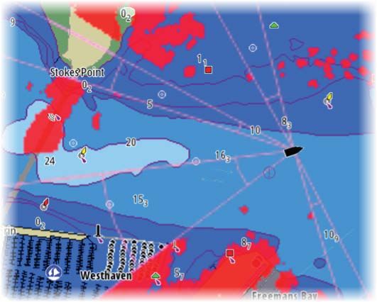
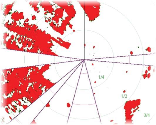
34 Software setup | HDS Live Installation ManualMain radar PPI Radar overlay on a chart Adjust open array park angle The park angle is the final resting position of the antenna relative to the heading line of the radar when the radar is set to standby. The antenna will stop rotating at the desired offset. Tune The automatic tuning will work well in most installations. The manual tuning is used if it is required to adjust the result from an automatic tuning. Adjust local interference reject Interference from some onboard sources can interfere with the Broadband radar. One symptom of this could be a large target on the screen that remains in the same relative bearing even if the vessel changes direction. Halo light Controls the levels of the Halo Radar blue accent lighting. The accent lighting can only be adjusted when the radar is in standby mode. Ú Note: The blue accent pedestal lighting might not be approved for use in your boating location. Check your local boating regulations before turning the blue accent lights ON. Reset radar to factory defaults Clears all user and installer settings applied to the selected radar source, and restores factory settings. Software setup | HDS Live Installation Manual 35
Ú Note: Use this option with caution. Take note of current
       settings first, especially those set by the operator if radar has
       already been in active service.

     Sonar settings

     Internal sonar
     Used for making the internal sonar available for selection in the
     sonar panel menu.
     When de-activated, the internal sonar will not be listed as a sonar
     source for any unit on the network.
     De-activate this option on units which do not have a transducer
     connected.

     Network sonar
     Select to see or share sonar data from this unit with other units
     connected to the Ethernet network.

     Network sonar mode
     The network sonar mode setting selects whether only one or
     multiple sonar sources can be selected at the same time.
     Ú Note: Changing the mode requires that all connected sources
       are restarted.

     Structure depth offset
     Setting for Structure transducers.

36   Software setup | HDS Live Installation Manual
All transducers measure water depth from the transducer to the
bottom. As a result, water depth readings do not account for the
distance from the transducer to the lowest point of the boat in the
water or from the transducer to the water surface.
B
A
• To show the depth from the lowest point of the vessel to the
bottom, set the offset equal to the vertical distance between the
transducer and the lowest part of the vessel, A (negative value).
• To show the depth from the water surface to the bottom, set the
offset equal to the vertical distance between the transducer and
the water surface, B (positive value)
• For depth below transducer, set the offset to 0.
Use temp data from
Selects from which source the temperature data is shared on the
NMEA 2000 network.
Installation
Use this dialog to setup and configure available sources.
Software setup | HDS Live Installation Manual 37Source
Select this option to display a list of sources available for setup. The
settings you make in the rest of the dialog pertain to the source
selected.
Source name
Select this option to set a descriptive name for the selected
transducer.
Depth offset
All transducers measure water depth from the transducer to the
bottom. As a result, water depth readings do not account for the
distance from the transducer to the lowest point of the boat in the
water or from the transducer to the water surface.
B
A
38 Software setup | HDS Live Installation Manual• To show the depth from the lowest point of the vessel to the bottom, set the offset equal to the vertical distance between the transducer and the lowest part of the vessel, A (negative value). • To show the depth from the water surface to the bottom, set the offset equal to the vertical distance between the transducer and the water surface, B (positive value) • For depth below transducer, set the offset to 0. Water speed calibration Water speed calibration is used to adjust the speed value from the paddle wheel to match the actual boat speed through the water. Actual speed can be determined from GPS speed over ground (SOG) or by timing the boat over a known distance. Water speed calibration should be performed in calm conditions, with minimal wind and current movement. Increase this value above 100 % if the paddle wheel is under reading, and decrease this value if it is over reading. For example, if the average water speed reads 8.5 knots (9.8 MPH) and SOG records 10 knots (11.5 MPH) the calibration value needs to be increased to 117 %. To calculate the adjustment, divide the SOG by the paddlewheel speed, and multiply the product by 100. Calibration range: 50-200 %. Default is 100 %. Water speed averaging Averages water speed by measuring your speed at a selected interval of time. Water speed intervals range from one to thirty seconds. For example if you select five seconds, your displayed water speed will be based on averaging over 5 seconds of sampling. Calibration range: 1-30 seconds. Default is 1 second. Water temperature calibration Temperature calibration is used to adjust the water temperature value from the sonar transducer. It may be required to correct for localized influences to the measured temperature. Calibration range: -9.9° - +9.9°. Default is 0°. Ú Note: Water temperature calibration only appears if the transducer is temperature capable. Software setup | HDS Live Installation Manual 39
Transducer type
     Ú Note: The transducer type is automatically set for transducers
       that support Transducer ID (XID) and is not user selectable.
     Transducer type is used for selecting the transducer model
     connected to the sonar module. The transducer selected will
     determine what frequencies the user can select during sonar
     operation. In some transducers with built-in temperature sensors,
     the temperature reading may be inaccurate or not available at all if
     the wrong transducer is selected. Transducer temperature sensors
     are one of two impedances - 5k or 10k. Where both options are
     given for the same model transducer, refer to paperwork supplied
     with transducer to determine impedance.

     Autopilot settings
     For the trolling motor autopilot, no special setup is required. See the
     operator manual for further details.
     The NAC-1 autopilot computer (outboard motor autopilot) requires
     setup as described in the following sections.
     Ú Note: The word rudder is sometimes used in menus and
       dialogs. In this context, the outboard motor acts as a rudder.

     Autopilot data sources
     Provides automatic and manual data source selection for the
     outboard autopilot.

     Commissioning
     Used to calibrate your boat’s steering (cable steer or hydraulic
     steering) with the NAC-1.
     Ú Note: The autopilot must be commissioned prior to first use
       and any time after autopilot default settings have been
       restored.

     Cablesteer rudder calibration
     1. Select Commissioning.
     2. Select Rudder feedback calibration.
     3. Follow the onscreen instructions.

40   Software setup | HDS Live Installation Manual
Ú Note: When centering the motor during the calibration
process, ensure that the motor is centered visually. The rudder
feedback calibration dialog may show the motor is centered (00
value) when the motor is not centered. After centering the
motor visually, press OK and the rudder center calibration
setting is set to centered (00 value).
4. Select Rudder test.
5. If the calibration does not pass the rudder test:
- Confirm motor is moving.
- Confirm rudder feedback reading moves accordingly.
- Check NAC-1 drive cable.
- Confirm motor can be manually moved smoothly in each
direction.
- Check for other mechanical issues.
- Check wiring connections.
- Repeat rudder calibration steps.
Hydraulic system calibration
Virtual rudder feedback (VRF) calibration is used for vessels with
hydraulic steering.
1. Select Commissioning.
2. Select VRF calibration.
3. Follow the onscreen instructions.
Ú Note: When the autopilot attempts to turn the motor during
the calibration process, ensure motor movement is noticeable
and that it is turning in the correct direction before selecting
Yes on the Virtual Rudder Feedback Calibration dialog. When
No is selected in the dialog, the NAC-1 reverses direction and
increases power the next time it turns the motor during the
calibration process.
Ú Note: You may have to select No more than once to ensure the
pump provides enough power to turn the motor at high boat
speeds.
Steering response
Used to increase or decrease the steering sensitivity. A low response
level reduces the rudder activity and provides a more loose steering.
A high response level increases the rudder activity and provides
Software setup | HDS Live Installation Manual 41more tight steering. A too high response level will cause the boat to
make S movements.
Troubleshooting
The following are possible symptoms or * messages displayed by
the MFD. If the problem persists after trying the recommended
action, contact support.
No active autopilot control unit
Probable cause: The NAC-1 computer has lost contact with the
active control unit.
Recommended action: Check the cable connections from the
NAC-1 and MFD to the CAN bus network.
No autopilot computer
Probable cause: The MFD has lost contact with the NAC-1
Computer.
Recommended action:
• Make sure the NAC-1 computer is powered.
• Check connections from the NAC-1 to the CAN bus network.
AP Position data missing*
Probable cause: Missing or invalid position data.
Recommended action:
• Check the GPS cable connections to CAN network.
• Check the GPS antenna location.
• Check that the correct position source is selected. (Run a new
source selection.)
AP Speed data missing (SOG)*
Probable cause: Missing or invalid speed data.
Recommended action:
• Check the GPS cable connections to the CAN network.
• Check the GPS antenna location.
• Check that the correct position source is selected. (Run a new
source selection.)
AP Depth data missing*
Probable cause: Missing or invalid depth data.
Recommended action:
• Check the depth transducer.
42 Software setup | HDS Live Installation Manual• Check transducer cable connections to the MFD or to the CAN network. • Check that the correct depth source is selected. (Run a new source selection.) AP Heading data missing* Probable cause: Missing or invalid heading data. Recommended action: • Check the compass cable connections to the CAN network. • Check that the correct heading source is selected. (Run a new source selection.) AP Nav data missing* Probable cause: Missing or invalid NAV data. Recommended action: • Check for valid data on the MFD screen. • Check the source selection setting. AP Rudder data missing (For Helm-1/ cable steer only)* Probable cause: • Rudder feedback signal missing due to a broken wire or connection. • Misaligned potentiometer in the Helm-1. Recommended action: • Check cable and connector. • Check the alignment as per the installation instructions. AP Off course* Probable cause: • The boat’s heading is outside the fixed off course limit of 20 deg. (Automatic reset when inside limit). • The boat speed is too low. • The response setting is too low. Recommended action: • Check the steering response setting and increase the steering response setting. • Increase the boat speed if possible, or steer by hand. AP clutch overload (For Helm-1/ cable steer only)* Probable cause: The clutch in Helm-1 is drawing too much current. Software setup | HDS Live Installation Manual 43
Recommended action:
     • Disconnect the Helm-1 and verify that the alarm disappears.
     • Check resistance of the clutch coil equals 16 ohms (pin 1 and 2 in
       connector).
     No rudder response (For Helm-1/cable steer only)*
     Probable cause: No response to rudder commands.
     Recommended action:
     • Check the cable connections between NAC-1 and Helm-1.
     • Check the Rudder FB potentiometer in Helm-1.
     • Check the Helm-1 drive motor.
     Rudder drive overload*
     Probable cause: The drive unit shuts down due to an excessive load
     or a short circuit.
     Recommended action:
     • Check the drive unit and drive unit installation.
     • Look for mechanical obstructions.
     • Check the manual steering.
     High drive temp*
     Probable cause: The NAC-1 drive output circuit is overheated due to
     excessive load.
     Recommended action:
     • Switch the Autopilot to Standby.
     • Check the drive unit (see “Rudder drive overload”).
     Drive inhibit*
     Probable cause: There is an internal NAC-1 failure causing the drive
     output circuit to shut down.
     Recommended action: Contact support.
     Low CAN bus voltage
     Probable cause: The CAN bus voltage is less than 9V.
     Recommended action:
     • Check cabling.
     • Check battery condition.
     • Check charging voltage.

44   Software setup | HDS Live Installation Manual
Fuel settings The fuel utility monitors a vessel's fuel consumption. This information is totaled to indicate trip and seasonal fuel usage, and is used to calculate fuel economy for display on instrument pages and the data bar. To use the utility, a Navico Fuel Flow sensor, or a NMEA 2000 engine adaptor cable/gateway with Navico Fuel Data Storage device must be fitted to the vessel. The Navico Fuel Flow sensor, does not require the use of a separate Fuel Storage device. Refer to the engine manufacturer or dealer for information on whether or not your engine provides a data output, and what adaptor is available to connect to NMEA 2000. Once the physical connection is made, ensure source selection is completed. Multiple engine installations using Fuel Flow sensors, or Fuel Data Storage devices, require setup of related engine location in the Device list. For general source selection information, refer to "Network settings" on page 48. Vessel setup The Vessel setup dialog must be used to select the number of engines, the number of tanks and vessel’s total fuel capacity across all tanks. Fuel flow configuration After the number of engines is set, it is required to set which fuel flow sensor is connected to which engine. Under Device list on the Software setup | HDS Live Installation Manual 45
Network page, view the Device Configuration dialog for each
     sensor, and set the Location to match the engine the device is
     connected to.
     Unconfigure - defaults the device which clears all user settings.
     Reset Fuel Flow - restores only the Fuel K-Value setting, if set in
     Calibrate. Only Navico devices can be reset.

     Calibrate
     Calibration may be required to accurately match measured flow
     with actual fuel flow. Access calibration from the Refuel dialog.
     Calibration is only possible on Navico’s Fuel Flow sensor.
     1. Start with a full tank and run the engine as it would normally be
         operated.
     2. After at least several liters (a few gallons) have been used, the
         tank should be fully refilled, and the Set to full option selected.
     3. Select the Calibrate option.
     4. Set the actual amount used based on amount of fuel added to
         the tank.
     5. Select OK to save settings. The Fuel K-Value should now show a
         new value.
     Ú Note: To calibrate multiple engines repeat the steps above, one
       engine at a time. Alternatively, run all engines simultaneously,
       and divide the Actual amount used by the number of engines.
       This assumes reasonably even fuel consumption on all engines.
     Ú Note: The Calibrate option is only available when Set to full is
       selected, and a Fuel Flow is connected and set up as a source.
     Ú Note: A maximum of 8 engines is supported using Fuel Flow
       sensors.

46   Software setup | HDS Live Installation Manual
Fuel Level With the use of a Navico Fluid Level device connected to a suitable tank level sensor, it is possible to measure the amount of fuel remaining in any equipped tank. The number of tanks must be set in Vessel Setup dialog, initiated from the Fuel setting options page, to allow discrete tank assignment of the Fluid Level devices. Select Device list on the Network page, and view the Device Configuration dialog for each sensor, and set the Tank location, Fluid type, and Tank size. For setting up the Instrument bar or a gauge on the Instrument page with Fluid Level device data, refer to the Operator Manual. Ú Note: A maximum of 5 tanks is supported using Fluid Level devices. Ú Note: Tank data that is output by a compatible engine gateway can also be displayed, however tank configuration for such a data source is not possible from this unit. Wireless settings Provides configuration and setup options for the wireless functionality. Refer to the Operator Manual for details about wireless setup and connectivity. Software setup | HDS Live Installation Manual 47
Network settings

     Network info
     Lists basic network information.

     Device name
     Assigning a name is useful in systems using more than one device
     of the same type and size.

     Auto configure
     The auto configure option looks for all sources connected to the
     device. If more than one source is available for each data type,
     selection is made from an internal priority list.
     Ú Note: This option provides the best configuration of available
       data sources for the majority of installations.

     Data sources
     Data sources provide live data to the system. When a device is
     connected to more than one source providing the same data, the
     user can choose the preferred source.
     Before commencing with source selection make sure all external
     devices and networks are connected and turned on. Manual
     selection is generally only required where there is more than one
     source for the same data, and the automatically selected source is
     not the one desired.

48   Software setup | HDS Live Installation Manual
Damping If data appears erratic or too sensitive, damping may be applied to make the information appear more stable. With damping set to off, the data is presented in raw form with no damping applied. Device list Selecting a device in this list will bring up additional details and options for the device. All devices allow allocation of an instance number in the configure option. Set unique instance numbers on any identical devices on the network to allow the unit to distinguish between them. The data option shows all data being output by the device. Some devices will show additional options specific to the device. Ú Note: Setting the instance number on a 3rd party product is typically not possible. Diagnostics Provides information useful for identifying an issue with the network. NMEA 2000 Provides information on NMEA 2000-bus activity. Ú Note: The following information may not always indicate an issue that can be simply resolved with minor adjustment to network layout or connected devices and their activity on the network. However, Rx and Tx errors are most likely indicating issues with the physical network, which may be resolved by Software setup | HDS Live Installation Manual 49
correcting termination, reducing backbone or drop lengths, or
         reducing the number of network nodes (devices).

     UDB
     Provides information on Ethernet activity.

     NMEA 2000 setup

     Receive waypoint
     Select this option to allow another device capable of creating and
     exporting waypoints via NMEA 2000 to transfer directly to this unit.

     Send waypoint
     Select this option to allow this unit to send waypoints to another
     device via NMEA 2000.
     Ú Note: The system can only transmit or receive one waypoint at
       a time on creation of that waypoint. For bulk import or export
       of waypoints see the operator manual.

     Backlight synchronization
     Select this option to allow display brightness synchronization across
     display units connected to the same network.

     NMEA 0183 setup
     The NMEA 0183 port(s) must be set to suit the speed of connected
     devices, and can be configured to output only the sentences
     required by listening devices.

50   Software setup | HDS Live Installation Manual
Receive waypoint Select this option to allow a device capable of creating and exporting waypoints via NMEA 0183 to transfer directly to this unit. Serial ports Specifies the baud rate and protocol for the NMEA 0183 interface. The baud rate should be set to correspond with devices connected to the NMEA 0183 input and output. Serial Output Selection determines whether the data is output via Tx lines, and will enable editing of the output sentences list. Serial output sentences This list allows control over which sentences need to be transmitted to other devices from the NMEA 0183 port. Due to the limited bandwidth of NMEA 0183 it is desirable to only enable the data that is required. The less sentences that are selected, the higher the output rate of the enabled sentences. Commonly used sentences are enabled by default. Ethernet/Wireless The NMEA 0183 data stream is output and made available to tablet devices and PCs, via the internal wireless or Ethernet. The dialogue provides IP and port data typically required for configuring the application on the third party device. Ú Note: Other MFDs cannot decode this information back to NMEA 0183, to use the data as a source. To share data a physical NMEA 2000 or NMEA 0183 connection is still required. Software setup | HDS Live Installation Manual 51
5
     3rd party support

     SmartCraft VesselView integration
     When a compatible Mercury Marine VesselView product or
     VesselView Link is present on the NMEA 2000 network, the engines
     can be monitored and controlled from the unit.
     When the feature is also enabled in the advanced settings features
     dialog:
     • A Mercury icon is added to the home page - select it to display
        the engine instrument panel.
     • A Mercury settings dialog is added - use this dialog to change
        engine settings.
     • Mercury and Vessel Control buttons are added to the control bar:
       - Selecting the Mercury button displays engine and vessel data.
       - Selecting the Vessel button opens the engine controller.
     When the features are enabled, the display may prompt the user for
     some basic configuration information.
     For more information, refer to the VesselView manual or engine
     supplier.

     Suzuki engine integration
     If a Suzuki C-10 gauge is available on the NMEA 2000 network, the
     engines can be monitored from the unit.
     When the feature is also enabled in the advanced settings features
     dialog:
     • A Suzuki icon is added to the home page - select it to display the
         engine instrument panel.
     For more information, refer to the engine manual or engine
     supplier.

     Yamaha engine integration
     If a compatible Yamaha gateway is connected to the NMEA 2000
     network, the engines can be monitored from the unit.
     When the feature is also enabled in the advanced settings features
     dialog:

52   3rd party support | HDS Live Installation Manual
• A Yamaha icon is added to the home page - select it to display
the engine instrument panel.
• If the Yamaha system supports Troll Control, a Troll button is
added to the Control Bar. Select this button to enable/disable
troll control and control the trolling speed.
For more information refer to the engine manual or the engine
supplier.
Evinrude engine integration
If an Evinrude engine control head is available on the NMEA 2000
network, the Evinrude engines can be monitored and controlled
from the unit.
When the feature is also enabled in the advanced settings features
dialog:
• An Evinrude icon is added to the home page - select it to display
the engine instrument panel.
• An Evinrude settings dialog is added - use this dialog to change
engine settings.
• An Evinrude button is added to the control bar - selecting this
button opens the engine controller. Use the engine controller to
control the engines.
A maximum of two control heads and four engines is supported.
For more information, refer to the engine manual or engine
supplier.
Power-Pole anchors
Power-Pole anchors, which can be controlled by the C-Monster
Control System installed on your boat, can be controlled from the
unit. To control the Power-Poles, you pair the Power-Poles with the
unit using Bluetooth wireless technology available in both products.
C-Zone
CZone connection to NMEA 2000
When interfacing to CZone network it is recommended to use a BEP
Network interface bridge to join the two network backbones
together.
3rd party support | HDS Live Installation Manual 53The CZone / NMEA 2000 Network interface bridge isolates the
power of the two networks, but allows data to be freely shared
between both sides.
The Interface Bridge can also be used for expansion of the NMEA
2000 network, when the maximum node limit (node = any device
connected to network) for the network has been reached or the
maximum cable length of 150 m will be exceeded. Once an
Interface Bridge has been fitted, a further 40 nodes and additional
cable length can be added.
The Network Interface is available from your BEP dealer. For more
information please refer to the BEP web site www.bepmarine.com.
NETWORK
67$786
5HG1HWZRUN
*UHHQ1HWZRUN
Network 1 Network 2
NETWORK INTERFACE
CZONE
NMEA2000 CZONE
CZone setup
In order to communicate with the CZone modules connected to
the network, the unit must be assigned a unique CZone Display
Dipswitch setting.
The functionality of the CZone system is determined by the CZone
Config File which is stored on all CZone modules and the HDS Live.
The file is created using the CZone Configuration Tool, a specialized
PC application available from BEP Marine Ltd, and associated CZone
distributors.
For more information, refer to the documentation provided with
your CZone system.
Assigning the dipswitch setting
Every product capable of controlling and viewing CZone devices
must be assigned a virtual dipswitch setting. This setting is unique
for each device. Typically it is set after the configuration file already
54 3rd party support | HDS Live Installation Manualexists on the CZone system, but it may also be set in advance. To do so, access the CZone menu on the Settings page. When the configuration is already available on the network, it will immediately commence uploading to the HDS Live once the dipswitch is set. Allow this to complete, without interruption. Setting CZone to display at startup With this option selected, the CZone control page is shown first, every time the HDS Live is powered up. Backlight Enabling this causes the HDS Live to synchronize its backlight setting with that of any CZone Display Interfaces set up to share backlight settings. Ú Note: CZone Config also needs to have the HDS Live set as a controller. 3rd party support | HDS Live Installation Manual 55
You can also read