Heat Pumps Code of Practice - Installation Guidelines Version 6.0 27.09.2018 - SEAI
←
→
Page content transcription
If your browser does not render page correctly, please read the page content below
Heat Pumps Code of Practice – Installation Guidelines
                  Version 6.0 – 27.09.2018

1                                            HPA Ireland – version 6.0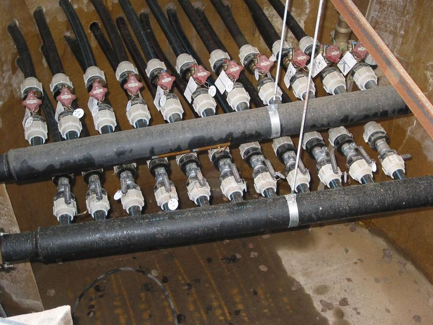
HEAT PUMP INSTALLATION GUIDELINES
1. HEAT PUMP DESIGN AND REGULATIONS
Heat Pump technology has been used successfully for more than 50 years and
the most important step in designing and installing a heat pump system is the correct
sizing of the heat pump. This has to be done accurately to allow the heat pump to
properly deliver the Heating (by covering the heat loss of the building) & DHW
requirements (depending on relevant hot water taping profile) for the proposed
dwelling/building. This is to be done in accordance with the current regulations and
guidance documents published by the relevant bodies. i.e. CIBSE, NSAI standards,
Building Regulations, etc. to allow the designer or installer of a heat pump to select
the most beneficial solution for the end user, from both a capital cost investment and
running & maintenance costs point of view. For new buildings the capital cost is not a
decisive factor in using or not the heat pump, as more and more heat pumps are being
used as the preferred heat source and also this initial cost can be easy enough
absorbed in the overall cost of building a new dwelling. As a retrofit solution though
the cost of installing a heat pump can be prohibitive, as it has to be done in conjunction
with some other major upgrades – fabric & ventilation of the building – , to ensure that
the new heat source will work efficiently and will suit this type of application.
Heat Pump efficiency is the ratio of the heating or cooling delivered to the
electrical energy required to operate the system using a refrigerant.
The ratios are given in two ways:
Coefficient of Performance (COP) – the ratio of heating delivered to the
electrical energy input
Energy Efficiency Ratio (EER) – the ratio of cooling delivered to the electrical
energy input
The higher the COP or EER, the greater is the efficiency of the heating or cooling
system. COP can be calculated by taking the heating output (in kW) and dividing it by
the electrical input (in kW). These values can be found in the energy rating label or
manufacturer’s information.
You can also get a Seasonal Coefficient of Performance or Seasonal Performance
Factor (SCOP or SPF) – the ratio of heating delivered to the electrical energy input on
an annual basis. The COP values reflects the efficiency of the heat pump in certain
laboratory testing conditions 7°C outdoor & 35°C flow temperatures, where the
SCOP/SPF looks at the annual efficiency of the heat pump and takes in account the
variation of the outdoor temperature throughout the year – usually the COP is greater
than the SCOP/SPF, but the lather is more of a true reflection of the efficiency of the
heat pump.
A Refrigerant is the fluid that facilitates the energy transfer to take place between
the outdoor and indoor, due its special physical & chemical properties and it is used
by all heat pumps. The EN378 F-Gas European Standard guides people in the
areas of design, construction, installation, operation and maintenance on
2 HPA Ireland – version 6.0
the Safety and Environmental use of vapour compression systems for
refrigeration, heat pumps, chillers and air conditioning systems.

        There are two main types of refrigerants: Natural type: i.e. ammonia, propane
and CO₂ and synthetic type: i.e. R134a, R407C, R410a and most recent R32. The F-
gas regulation is driving industry to use lower GWP refrigerants in many applications
and EU regulation (517/2014), which came into force on the 1st January 2015,
introduces a ban on new equipment using HFC refrigerants with a GWP of over 2500
by 2020. The regulation also introduces a phase down, related to GWP and measured
in CO2 equivalent tonnes, which will drive industry to use lower GWP options. As a
result, a new family of refrigerants – both pure fluids and blends – has been (and
continues to be) developed - these are Hydro Fluoro Olefins (HFO). A feature of many
of these products (and some existing refrigerants such as R32 and Ammonia) is that
they exhibit lower flammability, and hence a new classification has been introduced by
ASHRAE to cover this feature – A2L. (In the case of Ammonia the classification is B2L,
due to its toxicity).

     There are a few important things to be considered when designing the system and
sizing the heat pump, in accordance with NSAI recommendations the system “should
be designed and constructed in accordance with the Building Regulations, Irish
Standards, the EU Energy Performance of Buildings Directive (EPBD) and the Building
Energy Rating scheme (BER)”:

Heat loss calculations in accordance with NSAI SR50-1 should be done for the
proposed dwelling, either for new, renovation or retrofit project and the heat pump
should be sized in accordance with this and in-line with current recommendations
from SEAI regarding “Heat Pump Tool for DEAP 2016”. See below example of heat
loss calculations based on above standard based
“7.6 Fabric Heat loss
Fabric heat losses are losses directly through the walls, windows, doors, floors and
ceiling of the room. For ease of calculation, it is assumed that these losses are at a
uniform rate through each surface. The heat loss rates are obtained by multiplying
the area of each individual surface by the design temperature difference and the
heat transfer co-efficient called the 'U' Value. For further details reference should be
drawn from I.S. EN ISO 13789.
The 'U Value' of a building fabric is the thermal conductivity of a material (rate of loss
of heat in watts) that will flow through one square metre of the material when there is
a temperature difference of one degree Kelvin (K). To calculate the heat loss through
the whole wall for each degree difference, multiply; the ‘U’ value by the wall area and
then by the temperature difference between the inside and outside of the wall.
Design heat loss through wall = Surface area (m²) x 'U' Value (w/m²/°K)x
Temperature difference (ΔT)
Fabric Heat Loss (Watts) = Area (m²) X ‘U’ Value (W/m²x°C) X ΔT (°C)
The ‘U’ value of a material can be found from the manufacturer or from tables such
as that TGD Part L
Appendix B. Methods can also be found in I.S. EN ISO 6946 and also in the CIBSE
guide.
   I.    on SR50-1 fabric heat loss calculation and ventilation rates:

3                                                                  HPA Ireland – version 6.0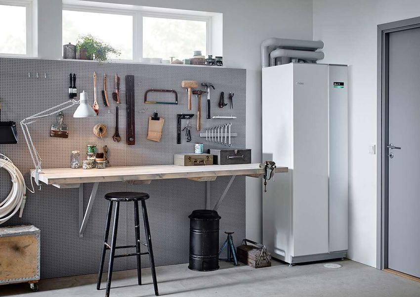
Domestic Heat Loss Calculation worksheet
ROOM Kitchen/Dining             Job Title                                                            Page of
room
 Design Room Temp 21            No. of air     Room Volume (meters)          Amount         Air       Design      Heat Loss
                                changes                                      of air to   change       Temp         Watts
                                per hour                                        be        factor        Diff
Subtract Outside           -3     ac/h                                        heated     W/m3.K        degC
Design Temp                                                                  per hour
                                                                               m3/h
Design Temp Diff           24                Length     Width     Height
                                               (m)       (m)       (m)

Ventilation Heat Loss               3         4.9        2.7        2.4      95.256       0.33          24        754.42752

Fabric Heat Loss                                                               Area      U-Value
                                                                                m2       W/m2.K

                   Floor                      4.9        2.7                  13.23       0.77          24           244.4904

         Ex Wall (Gross area)                 7.6                   2.4       18.24

                 Glazing                                 1.1       1.05       1.155        1.6          24            44.352

                   Door                                 1.75        2.1       3.675        1.6          24            141.12

Ex Wall (Nett area)                Subtract glazing and door areas from      17.085       0.35          24           143.514
                                         gross external wall area

     Ceiling or Roof (Gross area)             2.33      1.92                 4.4736              Heat gain from bathroom

            Roof Glazing                                  -          -                      -            -              -

Celing or Roof (Nett area)      Subtract roof glazing area from gross roof   4.4736       1.41          -1              -6
                                                   area

           Internal Wall 1                     -                     -           -          -            -              -

           Internal Wall 2                     -                     -           -          -            -              -

                Party Wall                    2.7                   2.4        6.48       1.02          11           72.7056

            4                                                                            HPA Ireland – version 6.0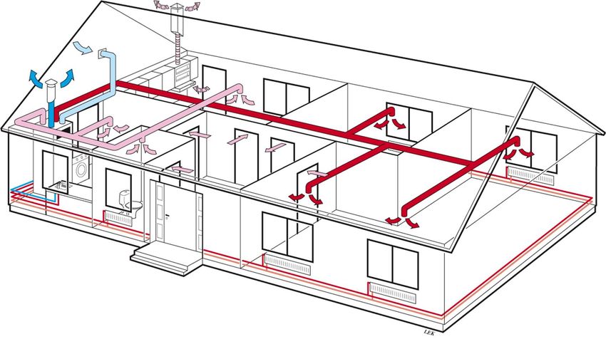
Other                       -          -         -          -            -           -             -

                Design Heat Loss from Room (Sum of Watts for all elements)                            1394.60952

Exposed Location?                  Yes      If Yes,     10      % to Design Heat Loss                 139.460952
                                              add

  High Ceiling?                    No       If Yes,      -      % to Design Heat Loss                      -
                                              add

                                                                             Total room Heat Loss     1534.070472

  7.7 Ventilation Rate
  The difference between the inside and outside temperatures and the rate at which
  the air enters and leaves the building will affect the ventilation heat loss. The
  ventilation heat loss rate of a room or building is calculated by the following formula;

  Rate of Heat Loss = V * N * ΔT * 0.33 where;
  V = the volume of air in the room (m3),
  N = number of air changes per hour,
  ΔT = Temperature difference between the outside and the inside, and,
  0.33 = is a constant factor. It represents the specific heat and density of air.

  The principal design considerations are:

         -   the required internal temperatures of each room,
         -   the design outside temperature (Range -1°C to -3°C), and
         -   the ventilation rate of the room(s).

  The calculations should include provisions to ensure that the heating up time of the
  entire system is not excessive. The general principle is to calculate the heat loss rate
  and the correct radiator (heat emitter) sizes, for each room in turn. Then total all heat
  losses to obtain a total figure.
  For further details reference should be drawn from I.S. EN ISO 13789.”
       II.    The hot water requirement to be taken in account is based on the hot water
              taping profile for the dwelling; to be noted that most of the heat pumps are
              sized to cover either the heating or DHW load, not the combined one, as the
              DHW production is done outside the heating demand. The DHW requirement
              is to be calculated according to EU Ecodesign Standardised User Profiles i.e.
              S-Small, M-Medium, L-Large and XL-Extra-large or based on occupancy
              average usage in line with current standards.
      III.    Oversizing the heat pump will significantly increase the installed cost for little
              operational saving, and will mean that the period of operation under part load
              is increased. Frequent cycling reduces equipment life and operating efficiency.

  5                                                                            HPA Ireland – version 6.0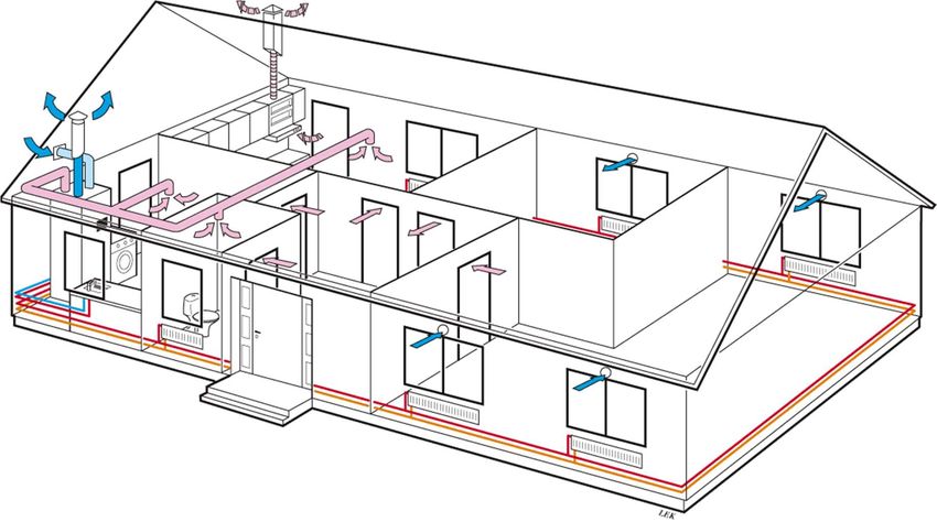
If the system is undersized, design conditions may not be met and the use of
          top-up heating, usually direct acting electric heating, will reduce the overall
          system efficiency
    IV.   A Heat Pump system can be designed to provide all the required heat – a
          monovalent system. However, because of the limitations in maximum heat
          output of single phase heat pumps it may be prudent to consider a bivalent
          system where the heat pump is designed to cover the base heating load, while
          an auxiliary system covers the additional peak demand – a bivalent system.
    V.    The majority of heat pumps have an operating temperature limit of 50°C –
          55°C in most applications. Reducing the output temperature required from the
          heat pump will increase its performance; ideally the flow temperature should
          be 35°C for UFH systems and 45°C for Fan coil/Low temperature radiator
          systems. These are not suitable for monovalent operation in combination with
          existing or traditionally sized, high temperature wet radiator distribution
          systems, or for providing all the domestic water heating as they will not be able
          to raise the water temperature to that required (60°C) to avoid the risk of
          Legionella. In this instance most heat pumps use a booster heater/electrical
          immersion to complete the Anti-legionella/Disinfection cycle. A few heat
          pumps, however, can provide output temperatures of up to 65°C and specially
          designed two stage compressor heat pumps can provide output temperatures
          of up to 80°C.
          NOTE: You should check with the Heat Pump Manufacturer/Supplier if the
          heat pump is suitable for your dwelling.
    VI.   Pipe sizing and circulation pumps are critical for the correct operation of the
          heat pump and the heating system. The designer/installer of the heat pump
          should make sure that a minimum DN25 (1” copper or 32mm PEX or MLC
          pipe) Flow & Return pipe work is in place from the heat pump to the distribution
          manifolds or motorized valves, to allow the heat pump to achieve its minimum
          required flow rates that enables the heat pump to deliver the output that it was
          designed for. Same for the circulation pump. Under sizing the pipe work will
          have a knock-on effect: the building will hardly reach the desired comfort
          temperature and as a result will have frequent cycling of the compressor,
          reducing its life time.
VII.      Correct sizing of the heat emitters – base on heat loss calculations, see
          paragraph “I “above – making sure that the heat output delivered by the heat
          pump can be efficiently transferred to the building and correct sizing &
          appropriate location of the DHW cylinder making sure that we are getting the
          benefits of the heat pump, as the DHW production is usually at much lower
          efficiency than heating efficiency.
VIII.     For renovations/retrofit projects only under certain circumstances existing
          pipework, heat emitters or DHW cylinder may be reused. For the heating
          system this is to be assessed based on provided heat loss calculations on a
          room by room basis. Firstly is to be assessed if the existing heat emitters
          output can meet the heat load required based on a lower flow temperature
          provided by the heat pump by using the manufacturer’s correction factors.
          i.e. – at Δt=50°C (flow temp. 80°C/return temp. 60°C and room temp. 20°C) a
          radiator’s output is 2,000Watts. Same radiator at Δt=30°C (flow temp.
          55°C/return temp. 45°C and room temp. 20°C) and correction factor of 0.424
          will only deliver 850Watts and furthermore at Δt=22.5°C (flow temp.
          45°C/return temp. 40°C and room temp. 20°C) and correction factor of 0.3 will
          only deliver 600Watts.

6                                                                   HPA Ireland – version 6.0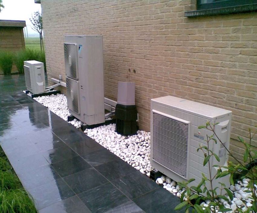
Reusing the pipework is not recommended, as most of the time the existing
        pipework has been designed for gas or oil boilers systems with higher flow
        temperatures and flow rates used which are not suitable for low temperature
        heat pump systems. The same principle will apply for existing DHW cylinders.
        If a high temperature heat pump is being used, capable of delivering 80°C flow
        temperature, it is possible to use the existing heating and DHW system,
        considering though the reduced efficiency/SPF of the new system.
        Also it is to be considered the compliance with the ErP Energy Label and EU
        ECODESIGN Lot 1&2 directive for combination heaters when considering
        reusing an existing DHW cylinder. See below guidance on determining the
        correct Δt for different flow/return and air temperatures:

        The following note should be considered when replacing the heating system
        i.e. Radiators, boilers etc. - this guidance note is for information only. The
        radiator is sized according to the heat required for a given room.
        The heat is measured in Watts (W) or British Thermal Units (BTUs) [1W =
        3.412 BTU]

        Heat requirement
        The heat required for a room depends on two factors: the temperature you
        want to maintain in the room and the rate of heat loss from that room. The
        following are recommended temperatures required for rooms depending on
        their type:

        Living areas i.e. – sitting room, dining room, play room:       18-21°C
        Other areas i.e. – kitchen, hall, toilet, bedrooms:             16-18°C
        Bathrooms (with shower):                                        22°C.
Once the heating requirement is known, based on heat loss calculations as shown
on paragraph I above, the radiator size can be calculated. For the example below the
room has a heat loss of 350W.

Radiator sizing
Radiator outputs are typically based on a water-to-air temperature difference Δt=50°C.
For heat pumps operating at low temperatures, this output will have to be in line with
the design flow temperature i.e. flow 45°C, Δt=22.5°C making sure that we are
achieving high efficiencies.
The higher the Δt value, the higher the radiator output will be. Traditional gas or oil
non-condensing boilers operate with higher flow and return temperatures 75/65°C,
while condensing boilers operate at lower flow and return temperatures 65/55°C, to
increase their efficiency. Similarly then for heat pumps we are aiming for as low
temperatures as possible 45/40°C, to increase their efficiency – see below examples.

                                 +
       ∆ =                                                −
                                  2

i.e. – standard efficiency boilers, 75/65°C and room temperature 20°C

                                75°C + 65°C
                          ∆ =               − 20°C = 50°C
                                     2

7                                                                   HPA Ireland – version 6.0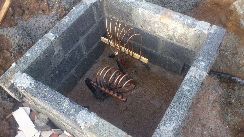
– condensing boilers, 65/55°C and room temperature 20°C

                                65°C + 55°C
                          ∆ =               − 20°C = 40°C
                                     2

– heat pump technology, 45/40°C and room temperature 20°C

                                45°C + 40°C
                         ∆ =                − 20°C = 22.5°C
                                     2

The temperature difference reduces the output of the same radiator. Many radiator
manufacturers supply information for radiator output based on a ΔT value of 50°. The
following table is an example of information provided by the manufacturer:

Where radiators are to be installed for different ΔT values, the stated radiator outputs
must be multiplied by a conversion factor to account for the different ΔT value.
Manufacturers should be asked to provide conversion factors for different ΔT values.
The following table is an example of conversion factors to be applied to outputs quoted
at ΔT 50°:

8                                                                 HPA Ireland – version 6.0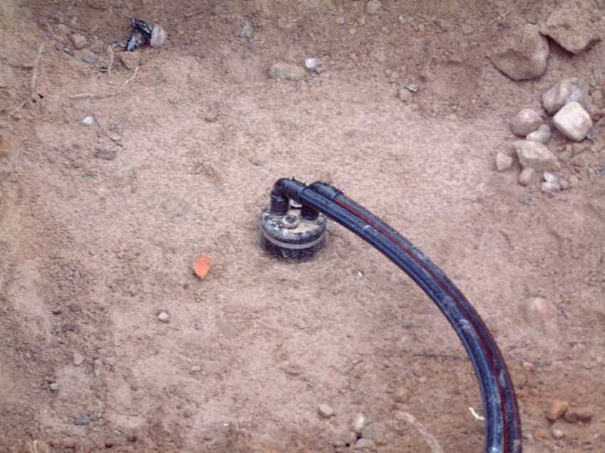
The conversion factor allows the calculation of the radiator output where the operating
temperatures result in a ΔT value different to ΔT 50°C. For example, where
replacement radiators with a ΔT value of 40°C are being installed, and the stated
output at Δ50°C is 480W, multiply by 0.7482 to get the output for the replacement
radiators.
                               480W x 0.7482=359W
The radiator output is now 359 W. This may mean you need to increase the size of the
radiator to meet the heat requirement of the room depending of the heat loss
calculated.

Also please see graph below showing the correlation between flow temperature, COP
and outdoor temperature.

          2. SPACE HEATING

        The first aim of the space heating control circuit is to operate the heat
distribution system at the lowest temperature that will still meet the required comfort
conditions. This will optimise the efficiency of the heat pump. The three main control
options are:

9                                                                HPA Ireland – version 6.0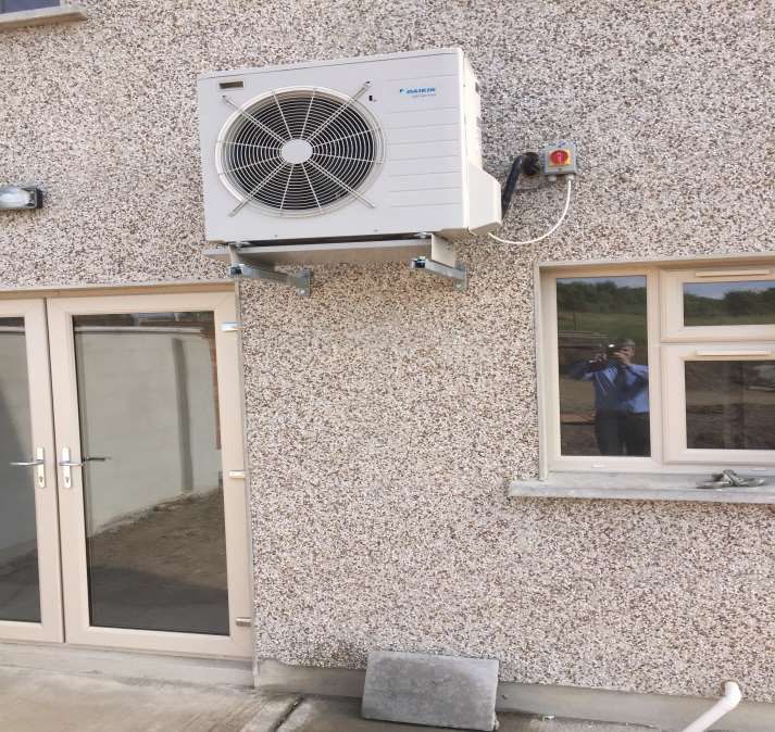
2.1 Weather compensation: This is the most efficient form of control. The
              output temperature from the Heat Pump is adjusted according to the
              outside air temperature. As the outside temperature rises the output
              temperature is reduced, so the Heat Pump never works at a higher
              temperature than necessary. In general an outside temperature sensor
              sends signals to a controller. This automatically controls the output
              temperature according to a factory set curve defining the relationship
              between the outside air temperature and the Heat Pump output
              temperature. For water distribution systems the operation of the heat
              pump compressor is usually controlled in response to the return water
              temperature, so this is lowered as the outside air temperature rises.
              Most heat pump manufacturers have the outdoor temperature sensor
              built in the outdoor unit. If this is not the case or if the unit is south facing,
              i.e. in a sun trap location, it is recommended to have an outdoor
              temperature sensor installed, ideally on a north facing wall, considering
              though that the heat pump supplied is capable of weather compensation
              control.

          2.2 Room thermostat/sensor control: A room temperature sensor located
              centrally in the house can be used in conjunction with an outside air
              temperature sensor to influence the curve control function (or weather
              compensation function). It is recommended the use of
              thermostats/sensors that have built-in LCD display showing the
              existing/desired room temperature or a type of temperature control
              system that will enable the end user to see these values.
              If there is a room thermostat/sensor controlling the temperature on one
              floor, it is not recommended to have this installed in a kitchen or room
              with opened fire; also its position has to be out of direct sunlight. These
              measures will enable a proper reading of the room temperature, without
              the influence of external factors.

          2.3 Fixed temperature: The Heat Pump is switched on and off by an in-built
              return temperature sensor and always operates up to its maximum
              working temperature. This method of control does not offer optimum
              savings from the Heat Pump. Usually a single room temperature sensor
              is used to control the operation of the heat pump compressor. In addition
              the operation of the Heat Pump can be controlled by a timeclock;
              however, for water-based distribution systems there will not be the same
              potential for intermittent heating as there can be with conventional gas
              or oil fired heating systems.
       With output temperatures between 35°C and 55°C the response time of the
heating system is long. Heat pump systems are therefore designed to maintain a
stable temperature rather than be able to raise the temperature quickly immediately
before occupation. Night setback can be applicable but with a setback of 2°C to 4°C.

          3. Heat emitter sizing

10                                                                     HPA Ireland – version 6.0
The heat losses of the building must be 100% covered by the heat emitters and
these should be designed and installed in accordance with the current NSAI SR50-1
standard for heat and ventilation losses.
The Heat Pump system must provide 100% of the calculated design space
heating requirement at the selected internal and external temperatures after taking
into consideration the flow temperature at the heat pump when it is doing space
heating. In exceptional outdoor temperatures, below design levels, the heat pump can
use a built-in back-up heater to cover the extra load – the temperature point where the
back-up heater is allowed to come on is called equilibrium temperature. Great care
should be taken in not oversizing the heat pump by considering too low outdoor
temperature design, as this will have the adverse effect on the performance of the heat
pump at higher outdoor temperatures resulting in cycling, lower efficiency and reduced
life expectancy of the unit. Performance data from both the heat pump manufacturer
and the heat emitter system designer/supplier should be provided to support the heat
pump selection. Where bivalent systems are being used, either for new or existing
dwellings, it is recommended that the heating base load should be covered by the heat
pump, enabling the end user/beneficiary of this system to get the benefits of a
renewable system and do not relay on a secondary space heater.
For installations where other heat sources are available to the same building,
the heat sources shall be fully and correctly integrated into a single control system. A
Heat Pump must be selected such that the combined system will provide at least 100%
of the calculated design space heating requirement at the selected internal and
external temperatures, the selection being made after taking into consideration the
space heating flow temperature assumed in the heat emitter circuit and any variation
in heat pump performance that may result. Heat pump thermal power output for the
purposes of this section shall not include any heat supplied by a supplementary
electric heater within the design temperature range.
To be considered that the use of UFH systems working up to 35°C results in
higher SCOP/SPF’s than the use of Fan coil/Low temperature radiator systems
working up to 45°C; the control & responsiveness though of an UFH system is not as
the same level compared with a Fan coil/Low temperature radiator system – each
system therefore will have its own advantages & disadvantages. Air-to-air fan coil units
are becoming more and more popular, especially for certain retrofit applications,
typically with air heated at 20°C and refrigerant not exceeding 30°C.
Also the Exhaust-air heat pumps are becoming a more popular solution
especially for passive-houses and apartment developments due to the fact these have
a Mechanical Ventilation and Heat Recovery (MVHR) part of the indoor unit. It uses
the MVHR pipe distribution system to provide heating or cooling without the need for
the traditional “wet” distribution system. Also the DHW cylinder is part of the same
indoor unit.
For installation of Heat Pumps in existing buildings with existing heat emitters
this will require special attention. More than likely the existing heat emitters have been
sized and installed to suit a heat source that can provide a much higher flow
temperature i.e. 70-80°C, therefore the existing heat emitter may not be suitable. In
this instance we would recommend that these would be replaced, as well the
distribution heating pipework to make sure that minimum flow rates required for the
heat pump to deliver the required thermal output can be achieved. Nevertheless if
fabric & ventilation improvements have been carried out to the existing building i.e. –
11 HPA Ireland – version 6.0walls & roofs U-Values have being considerably improved, glazing & doors have been
upgraded, the existing system may be suitable; in saying that the existing heat emitters
should be checked to make sure the thermal outputs of these will suit the new heat
source and existing pipe work is suitable for the proposed application. Some Heat
Pumps that can deliver flow temperatures up to 80°C could be considered as a direct
replacement without the need of replacing the existing heat emitters of pipe work;
these type of applications though have lower SCOP/SPF’s than the typical 50-55°C
ones.
Minimum output from the compressor is to be absorbed by the installed system,
making sure that minimum flow rates and minimum Δt’s are being maintained in
accordance with manufacturer’s specifications.
4. Domestic Hot Water – DHW
The Heat Pump is likely to be operating less efficiently when providing domestic
water heating because higher output temperatures are required. Where the domestic
hot water system includes a storage cylinder, it will be cost effective to make maximum
use of any cheaper tariff periods for electricity. The basic control device is therefore a
timeclock and a tank thermostat. The auxiliary immersion heater should not be able to
operate at the same time as the heat pump is supplying heat to the domestic hot water
cylinder. A tank immersion thermostat or sensor, rather than a strap-on one, should
be used to sense the stored water temperature as it is more accurate.
The DHW cylinder should be located within the envelope of the building in a
heated space, ideally in airing cupboard or hot press, minimising the heat losses from
the cylinder to the surroundings. If the DHW cylinder cannot be located within the
envelope of the house it should be brought to the end users attention that the running
costs for DHW production will generally be higher.
In general Heat Pumps will not carry out space heating at the same time as
domestic hot water production. The Heat Pump manufacturer will recommend the
domestic hot water cylinder heat exchanger or coil specification. Domestic hot water
heat exchangers for Heat Pump systems require a much greater heat exchanger
performance as compared to traditional combustion-based heat sources (i.e. boilers).
For coil-type heat exchangers, this usually requires a significantly greater heat
exchanger area.
There are 3 main types of DHW storage cylinders:
Integral storage cylinder, where the Heat Pump’s heat exchanger is
within the same casing with the DHW cylinder;
Separate storage cylinder, where the Heat Pump’s heat exchanger is
outside the casing of the DHW cylinder and
Fresh water technology, which is an integral thermal store and the DHW
production is done instantaneous, therefore not stored.
5. Electrical requirements
12 HPA Ireland – version 6.0All electrical work to be carried out is to be in compliance with current electrical
regulations i.e. RECI standards and completed by a RECI certified installer.
On completion of the electrical work the home owner should be provided with
a RECI Certificate/Commissioning form stating that all work was completed in
accordance with the current legislation.
Heat Pump manufacturers to provide all relevant data, installation manuals,
load requirements, etc. to make sure that the Heat Pump and all heat pump related
equipment is installed in accordance with the manufacturer’s specification and current
electrical regulations.
It is recommended the installation of electrical meters for the outdoor and indoor
units, if applicable, to separate the heat pump electrical usage from the domestic
electrical usage.
6. Commissioning & Maintenance
6.1 Commissioning
Heat Pump systems shall be commissioned according to the manufacturer’s
instructions and the system design parameters and an Energy Label for the
combination system – heating & DHW should be provided for the end user. The
designer/installer of the system should provide the “designer/installer sign-off form”
making sure that all relevant data is made available for the completion of the final BER
assessment.
Heat Pump Association of Ireland will be issuing a “HPA Passport” enabling
each manufacturer to certify their installers, confirming therefore that they have been
trained & certified to install their product in conformity with manufacturer’s specification
and corresponding Irish legislation.
A handover package to home owner has to be made available, so the home
owner can have a basic understanding of the system installed. This should include the
end user’s guide for the heat pump, heating, DHW and controls installed. Also is
recommended the commissioning form to be part of this package stating all parties
involved in completing the installation – i.e. mechanical contractor, electrical contractor,
F-Gas refrigeration engineer (if applicable), commissioning engineer, etc. alongside
with the service/maintenance recommendations.
Label indicating the flow rate required by the Heat Pump shall be fixed on the
manufacturer’s equipment. The heat pump and its associated pipework shall be
flushed and to all air removed from the installed pipework. The installation shall be
physically inspected and commissioned by a suitably qualified engineer, trained and
registered with the manufacturer to ensure the system is installed and operates as per
the manufacturer’s specifications. As part of the Heat Pump commissioning the
engineer has to make sure that the Heat Pump is working in accordance with the
provided performance parameters, designed flow & return temperatures are being
achieved for both heating and DHW production.
13 HPA Ireland – version 6.0It is considered good practice, the use of a pre-commissioning form provided to
the installer and confirmation that all recommended pre-commissioning work has been
completed prior to the commissioning engineer attending site.
For Air-to-water heat pumps the commissioning engineer has to ensure that the
minimum air circulation is being met by checking the location & installation details of
the outdoor unit and if changes are to be made, recommendations are to be given to
the installer/end user for these to be completed. If the Air-to-water heat pump used is
Monobloc type to ensure that an anti-freeze fluid mixture been used that will protect
the Heat Pump hydraulic components in freezing conditions in the event of a power
failure.
6.2 Maintenance
Heat Pumps can operate for 20 years or more, but they do require regular
scheduled maintenance. The installer should leave written details of any maintenance
checks you should undertake to ensure everything is working properly. Consultation
should be made with your supplier for exact maintenance requirements before you
commit to installing a Heat Pump. Please see below some of the typical maintenance
requirements for indoor units and outdoor units, where applicable:
6.2.1 Indoor units:
Cleaning the unit
Checking heating & DHW on/off temperatures
Electrical connections safe & sound
Water filter, water pressure and expansion vessel pressure
3 way valve changing from CH to DHW
Switch box
Booster heater cutting on/off - if applicable
6.2.2 Outdoor units:
Cleaning the unit, especially the coil as dirt, cobwebs, etc. can have
an effect on the efficiency of the heat pump; the fins are to be cleaned
with soap & water, no other chemical substances
Fins to be straightened, if necessary
Electrical connections safe & sound
2. HEAT PUMP TYPES
2.1 AIR SOURCE HEAT PUMPS – Air-to-water, Air-to-air and Exhaust-
air
Air source heat pumps work by using electrical energy to extract energy from
the outside air and transfer it inside as heat, which makes it an efficient way of heating.
There are two main types:
I. AIR-TO-WATER where the extracted energy from the outside air is being
transferred through a heat exchanger to water; these systems can
provide full Heating & DHW production
14 HPA Ireland – version 6.0II. AIR-TO-AIR Heat Pumps where the extracted energy from the outside
air is being transferred through a heat exchanger to air; these systems
can provide full Heating.
III. EXHAUST AIR Heat Pumps where extracts heat from the exhaust air of
a building and transfers the heat to the supply air, hot water and/or
hydronic heating system
The main components are as follows:
Evaporator: A heat exchanger that absorbs heat from the surroundings, (the outdoor
unit).
Compressor: Reduces the refrigerant gas volume by compressing it, causing the gas
temperature and pressure to rise, and pumps the refrigerant around the
pipework/system. The compressor may operate as a fixed- or variable speed system.
Condenser: A heat exchanger that releases heat to the surroundings, (the indoor unit).
Expansion valve: Allows the refrigerant condensate (liquid) to expand, lowering the
pressure and temperature.
Coil/pipework: Continuous, closed-circuit tubing through which refrigerant flows and
heat transfer occurs. The pipes generally have fins to increase the surface area for the
heat exchange process.
Refrigerant: The compound that circulates through the heat pump system in liquid and
gas state, alternately absorbing and releasing heat
Reversing or 4 way valve: Changes the direction of flow of the refrigerant to reverse
the heat pump function from heating to cooling or vice versa. The reversing valve also
allows the pump to switch into defrost mode
Fan(s): Draws air across the evaporator coil (for heat extraction) and moves air away
from the condenser coil (for heat distribution/removal).
There are five main processes in the cycle:
1. In the evaporator (outdoor unit), low-pressure, low-temperature liquid refrigerant
absorbs heat from its surroundings and evaporates, converting to a gas state and
absorbing energy as it does so (latent heat of evaporation).
15 HPA Ireland – version 6.02. It passes through the compressor where the low temperature gas is reduced in
volume, resulting in a rise in both temperature and pressure.
3. As a heated and high-pressure gas, it passes through the condenser (indoor unit)
where the gas condenses (latent heat of condensation) with a release of heat to:
the water flowing on the other side of the heat exchanger and using a circulating
pump we transfer this energy into the heating & DHW system – Air to water
system.
or to the air surrounding the coil, as a fan moves the warmed air away from the
coil it’s distributing the heat it throughout the indoor space – Air
to air system.
4. Still under pressure, the cooled refrigerant, now in liquid state, passes through the
metering device, where rapid expansion results in a reduction in pressure.
5. In the low-pressure, low-temperature state, the refrigerant flows back into the
evaporator, and the cycle is repeated.
The efficiency of an Air Source Heat Pump system is varies along with the
temperature differential between indoor and outdoor air and the require flow
temperature. A Heat Pump’s rated efficiency/COP is for an outdoor temperature of
7°C and flow temperature of 35°C, so when designing a system it is important to
understand how it will perform at lower temperatures. When the Heat Pump is in
heating mode, as the difference between outdoor temperature and desired indoor
temperature increases, the efficiency of a Heat Pump system decreases. Different
Heat Pumps will perform very differently at sub-zero temperatures – some may keep
performing down to -25˚C while others will struggle at temperatures below freezing.
Another temperature-related factor that can impact on efficiency is the extra
energy that may be required for defrosting at low temperatures. At just a few degrees
Celsius, any water vapour in the air will start to condense and freeze onto the
evaporator (outdoor heat exchanger) coil. This will disrupt the heat flow, and the coils
must be de-iced for heating to be able to continue. Certain Heat Pumps don’t require
a buffer vessel as part of the heating system but they do require a minimum volume
of water to be contained within the pipework, to allow the defrost cycle to happen – i.e.
20-25ltr.
For optimal Heat Pump efficiency, a system must be correctly sized to minimise
energy losses that occur during the defrost cycle. The defrost cycle is necessary to
remove ice build-up on the evaporator coil. Ice build-up occurs at around at 0-4˚C
(especially in high humidity), when any water vapour in the air will start to condense
and freeze onto the evaporator (outdoor heat exchanger) coil. This will disrupt the heat
flow, and the coils must be de-iced for heating to be able to continue. To remove ice
build-up on the coils, most Heat Pumps have a defrost cycle where the system
switches into cooling mode (taking some heat from inside), which could effectively cool
the room.
Some systems have a closed loop cycle to use waste heat from the
motor/compressor to defrost the coils. While this is occurring, no heat is supplied to
indoors. The defrost frequency and performance are critical to Heat Pump efficiency.
Undersized Heat Pumps will need to defrost frequently in low ambient temperatures,
reducing the system’s ability to reach and maintain set point. If the defrost cycle
16 HPA Ireland – version 6.0operates too frequently or if it does not operate often enough, it will not provide
sufficient heating, and Heat Pump operation will be compromised.
The defrost cycle control is either:
a time-temperature defrost starting and stopping at pre-set times (30-, 60- or
90-minute intervals); or
on-demand defrost, which is generally more efficient because it operates only
when it detects frost build-up on the outdoor coil by monitoring air and coil
temperature, outdoor airflow, pressure differential across the coil and
refrigerant pressure. Most ASHP have an on-demand defrost control.
Systems that include a dry-coil defrost cycle briefly run the outdoor fan at maximum
speed before the system starts to heat again, to remove any water that may still be on
the coil fins and would immediately refreeze. This operation can be seen by water
vapour blowing from the outdoor unit before the heating cycle resumes.
Correct Heat Pump sizing is critical to efficiency and performance. The unit should
be selected for the heating load that is required. If the Heat Pump is too small or too
large, the system will use more energy than necessary, increasing running costs and
losing efficiency, and heating/cooling requirements may not be met.
A correctly-sized Heat Pump system, when compared to a poorly-sized system,
will have:
shorter total compression run times and start on/offs
lower frequency operation speeds
reduced defrost mode running
all the above translated in overall lower heat pump running costs.
Installing an undersized Heat Pump unit will significantly increase running costs, to
the extent that the extra annual running cost will be more than the cost of installing a
unit that is the next size up. Where a large-capacity Heat Pump is required or the
space being heated is large, installing two smaller units may give better heat
distribution within the space and better control than the large single unit.
There are two main types of Air-to-water heat pumps:
17 HPA Ireland – version 6.0 MONOBLOC where the heat exchanger to transfer the energy from
compressor to water is built by the compressor in the outdoor unit. This type of
Heat Pump require water based Flow & Return connections
SPLIT type where the heat exchanger to transfer the energy from compressor
to water is built by the in the indoor unit. This type of Heat Pump requires F-
Gas Refrigerant pipe work connections. In this case we could have a WALL
HUNG INDOOR unit and an INTEGRAL INDOOR UNIT.
Typically the MONOBLOC & SPLIT with Wall Hung unit connect to a Separate
DHW Cylinder and the SPLIT with Integral unit has the DHW cylinder built-in
the indoor unit.
Both type of Heat Pumps Monobloc & Split are widely used each of these having
the own benefits, making either/or the other the preferred unit mostly driven by
installers. Please see below recommendations when locating the outdoor, indoor and
cylinder, also some installations examples:
There are a few important things to be considered when deciding on the location
of the outdoor unit and indoor unit/cylinder:
1. OUTDOOR UNIT: most important is that proper circulation of air all around
the unit being provided; lack of this will cause lower efficiencies and too
often defrost cycles resulting in high running costs - this to be done on every
installation in accordance with manufacturer’s specifications.
2. The OUTDOOR UNIT should ideally be located in close proximity of the
dwelling and by doing this we are ensuring that we are minimizing the pipe
run between the outdoor and indoor/cylinder, therefore reducing the pipe
heat losses. Is to be taken in account that especially during winter time
condensation is going to be generated from the evaporating coil, so
provisions are to be made that the condensate is being collected and
drained away. The installer is to ensure that under no circumstances the
18 HPA Ireland – version 6.0condensate will be draining on the foot path as this can freeze during winter,
creating a hazard for the home owner.
3. The OUTDOOR UNIT can be mounted at ground level feet ensuring that a
minimum gap is maintained between the ground level and the bottom of the
unit, so no debris can be accumulated underneath the unit. If the unit is
installed at height, it to be confirmed by the manufacturer what is the
maximum permissible height and what are the implications regarding the
future service and maintenance of the unit.
4. The OUTDOOR UNIT can create a certain level of noise – to be confirmed
by each manufacturer – and in certain conditions, depending on the site
limitations is it to be agreed the suitability of the installation in close proximity
of bedrooms. Most heat pump manufacturers have a “quiet level” function
that can be activated, limiting the noise produced within certain time
schedules.
5. The INDOOR UNIT and CYLINDER or INTEGRATED INDOOR UNIT that
contains the cylinder, should be located as centrally to the dwelling as
possible, allowing a good balancing in the heating and DHW distribution
pipework. This should be installed in accordance with the current Heating &
Plumbing Regulations ensuring servicing and maintenance space is
provided around the unit, in accordance with manufacturer’s specifications.
Please see below some examples of OUTDOOR and INDOOR/CYLINDER
installations:
Air-to-Air Systems:
19 HPA Ireland – version 6.0Air-to-Water Systems: 20 HPA Ireland – version 6.0
21 HPA Ireland – version 6.0
Exhaust Air Heat Pumps - EAHP
Overview

Used in air-tight, low energy homes and apartments, where ventilation is a must and
the major heat loss of the dwelling is due to (the necessary) air changes, EAHP
technology was developed in Denmark and Sweden in the early 70’s during the oil
crisis. Air is drawn through ducts to the heat pump usually from the bathrooms,
utility and kitchen areas. The cold waste air is discharged to outside through another
duct, and condensation to a drain. Not only that, the additional heat generated
internally from lighting, people and domestic appliances is also utilized through heat
recovery. These heat pumps are normally used in new low energy homes and rarely
suitable for retro-fits.

Heat recovered from the exhaust air may also be augmented by additional outside
air drawn into the machine. Heat is transferred to the hot water system and the

22                                                               HPA Ireland – version 6.0
heating system via radiators, floor heating or sometimes to an air heating battery in a
supply air heating system.

Types

There are three main types: -

     1. EAHP units that provide space and water heating with inlet air ducts only –
        outside air is drawn into the building through special air inlets fitted with filters
        and volume dampers located in the outside walls of living areas and
        bedrooms. As you can only obtain a limited amount of heat from the building’s
        waste air, additional energy may be taken into the machine from a
        supplemental air supply.

EAHP with Inlet only ducting – type 1

                                                               Specialised air inlets with filters 1

     2. EAHP units that provide space and water heating with both supply and
        exhaust inlet air ducts

23                                                                       HPA Ireland – version 6.0
EAHP with supply and exhaust ducting - type 2
3. Units that heat hot water only from ventilation often from the room they are
located in, or adjacent bathrooms. These usually feature an additional built-in
heat source suchas an electric back-up immersion but may also have heating
coils for interconnectuion to the heating system, solar thermal or even both.
EAHP Hot Water Only - Type 3
Points to Note The heating systems for EAHP types 1 & 2 are usually radiators or
floor heating and are similar in nature to those used with air to water or ground-
24 HPA Ireland – version 6.0source heat pumps in that they are usually low temperature systems with the UFH
running in the 28° to 40°C range and radiators to max 55°C. Those systems are also
usually variable in temperature with the load determined by weather compensation.
Important Design & Installation Points
1. The (types 1 & 2) EAHP must not be installed in buildings with uncontrolled
ventilation infiltration, open fireplaces, poor insulation or a heat demand that
exceeds the output of the chosen unit from the heat pump process alone.
Shortfalls in energy needed may in those cases be provided by supplemental
electric heating for instance leading to customer complaints about high
running costs.
2. Ventilation ducting systems need to be properly designed to ensure sufficient
air flow to the heat pump. This is a critical item – without sufficient air flow the
EAHP will not function properly.
3. The extract air, from which the EAHP extracts energy as its heat source, must
be well insulated if not running within the heated fabric of the building (passing
through attics etc.)
4. Setting fan speeds and balancing of air flow is critical for correct operation,
conservation of energy and to minimise noise.
5. Use of attenuators or acoustic flex ducting at the ventilation entry / exit points
on the heat pump may need to be considered.
6. Proper ducting systems must be used and to minimise required fan power and
ensure correct airflow with reduced noise. Rigid metal, plastic or a bespoke
system with manifolds / foam EPE ducting should be considered.
7. Where flexible ducting is used, often for instance from the EAHP to the
ducting spigots from the ceiling overhead, bear in mind access to the jubilee
clips for future replacement of those ducts…i.e. the ends of the flexible
ducting should not ‘vanish’ into the ceiling or plastered walls!
8. The discharge or waste air from an EAHP can be very cold (from 1° and often
as low as -15°C) so it is critically important that that run of ducting is to be
insulated with diffusion tight insulation or to be made from EPE foam. ANY
Gaps in insulation will lead to condensation on ceilings or water running down
the discharge duct and into the machine causing damage.
9. A correctly plumbed drain is required from an EAHP for disposal of
condensate and potential discharge from the safety valves’ tundish.
10. EAHPs are usually located within the house or apartment, in a hot press,
utility room or even kitchen. They should NOT be located in a garage or
outhouse!
11. The manufacturers’ installation guidelines should always be closely adhered
to and installers should be trained by the relevant manufacturer or agent for
product specific installation procedures.
12. The end user should be instructed on correct operating use and routine
maintenance items such as air filter changing etc.
25 HPA Ireland – version 6.0Typical Exhaust Air Heat Pump for Heating & Hot water 26 HPA Ireland – version 6.0
27 HPA Ireland – version 6.0
2.1 GEOTHERMAL Heat Pumps – Ground source closed and opened
              loop
Overview

With the aid of a ground source heat pump, solar energy stored in the ground can be
collected and used to heat your home. Often referred to as geothermal heating, the
heat collected is mostly from the sun in fact and not the earth’s core.

Warmth builds up underground from the first days of spring when the surface
temperature of the earth starts to increase, to high summer, when the rays of the
midday sun penetrate down into the ground. Warm rainwater also permeates the
upper layers of the ground. By the time the autumn leaves are falling, there’s enough
energy stored in the ground to heat up your house throughout the coldest winter. A
heat pump captures and upgrades this naturally occurring warmth, so even if the
summer seems wet and cool, it can still provide enough energy to maintain a
comfortable indoor temperature throughout the coldest winter.

Ground source heat is pure, stored, solar energy that is retrieved from deep in the
ground with a bore-hole, the bottom of a lake or a few metres below the lawn. The
most suitable is determined by the house's energy requirement, the existing heating
system and the plot. The system provides a convenient supply of heat and hot water,
and can also provide cooling during hot days. The tubing called a collector which is
buried in the garden or placed in a borehole contains a mixture of water and antifreeze.
(there are also DX or Direct Evaporating heat pumps detailed in a separate section).

28                                                                HPA Ireland – version 6.0
Types of Ground Source Heat Pumps (GSHP)
There are three main types of GSHP:
Brine to Water – the most commonly used type takes heat energy from closed loops
buried in the soil, placed in a lake or through a borehole probe.
Water to Water –Open-Loop System This type of system uses well or surface body
water as the heat exchange fluid that circulates directly through the geothermal heat
pump system. Once it has circulated through the system, the water returns to the
ground through the well, a recharge well, or surface discharge. This option is practical
only with an adequate supply of relatively clean water, and if all local codes and
regulations regarding groundwater discharge is met.
DX (direct exchange) or Direct Evaporation These heat pumps use copper or
aluminium pipes filled with the refrigerant gas and normally coated with a PE plastic
layer to directly absorb heat energy from the earth in horizontal arrays
(Ground source heat pumps (GSHP) work by using electrical energy to extract energy
from the ground or ground water and transfer it inside as heat, which makes it an
efficient way of heating. There are two main types/three main types
I. GSHP CLOSED LOOP where the extracted energy from the ground is
being transferred through a closed loop either horizontal or vertical pipe
arrangement using a brine/glycol mixture to harvest the energy from the
ground
II. GSHP CLOSED LOOP Direct Evaporating or DX where the extracted
energy from the ground is being transferred through a closed loop either
horizontal or vertical pipe arrangement using a refrigerant to harvest the
energy from the ground
III. GSHP OPENED LOOP where the extracted energy from the ground is
being transferred through an opened loop either horizontal or vertical
pipe arrangement using the energy from the ground water)
THE ABOVE 2 CLSIFICATIONS TO BE AGREED BY HPA MEMBERS!
The three main components are, as follows:
1. The collector (or loop) - this extracts energy from the ground. There are
several different types and layouts of collectors, and these are described later
in this chapter
2. The heat pump - converts the energy from the ground to usable energy in
your home for heating or cooling and DHW
3. The distribution system – maintains your home at a constant temperature by
providing heat or cooling through radiators or underfloor heating.
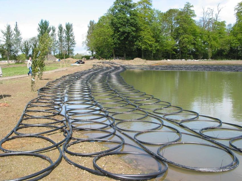
29 HPA Ireland – version 6.0There are four main types of CLOSED LOOP brine/glycol mixture collectors: horizontal, vertical, slinky and pond loops – see figure below: General Points to note Unlike gas and oil boilers, heat pumps are generally designed deliver heat at lower temperatures over much longer periods. During the winter they may need to be on constantly to heat your home efficiently…note this does not mean the compressor, the ‘engine’ of the heat pump is always on, but the control systems’ strategy usually will be able to call on it as necessary to maintain the balance of heat required for the building versus the temperature outside. You may also notice that radiators won't feel as hot to the touch as they might do when you are using a gas or oil boiler which is firing heat into the building in timed ‘bursts’…. You will be more comfortable allowing the heat pump to calculate and maintain the warmth (and perhaps cooling) of the building and production of hot water rather than the occupants trying to do this with switches or timers. Note that whilst pipework design and principles may seem to be broadly similar to the installation of an oil or gas boiler, there may be some differences. For instance, a buffer tank may be required, or else a strategy for the disposal of heat as the heat pump’s ‘work-load’ is satisfied and it waits to switch off for a short period. Heat pumps with fixed speed compressors as a rule will need a buffer tank sized at 20L per kW output, inverter or variable speed machines will be able to cope with much smaller buffer tanks. Usually, the heat pump manufacturer will provide design guidance and particular recommendations for their systems’ layouts and these as a rule should be closely studied and adhered to. Water travelling through the heating system will be at a lower temperature than oil/gas systems so less energy can be passed through smaller pipes; for this reason, it is critical that careful attention is paid to the system design and pipe dimensions. It has been said the three most important things in heat pumps are circulation, circulation, circulation! Note also that there is a relationship between the size and output of a heat pump to the size of hot water tank selected. The hot water tank will generally either be a tank- in-tank type with some buffer volume or at least have a very large heating coil or heat exchanger. Most standard or existing cylinders in retrofit situation will not be suitable for a heat pump. It is important again, that the manufacturers’ advice should be closely adhered to. The choice of a GSHP means that there is no outdoor machinery such as with an Air to Water heat pump. In cold weather the ground temperature will give higher efficiencies over air to water and there is energy lost to defrosting. Another advantage of the GSHP is that especially when used with a borehole, they can provide free cooling usually used in conjunction with floor heating or fan coils. Unwanted solar gain is transferred to the rock where it may be reclaimed later. 30 HPA Ireland – version 6.0
Location of plant Most modern ground source heat pumps for domestic dwellings are
quiet enough and built to an appliance styled finish that it is usually best practice to
locate the heat pump in the utility room or somewhere convenient within the house or
building to be heated. Many are even available with the hot water tank integrated into
the same fridge-like casing saving further on installation time and adding to efficiency.

Locating heating equipment (and hot water cylinder) in a remote shed or garage will
incur a loss of efficiency and higher installation and running costs of course!

Horizontal Collectors When collecting heat from a horizontal field array of pipes the
area selected will need to be approximately 2 ½ to 3 times the floor area of the building
being heated and are normally placed one metre below the lawn and at least 1 to 1.5M
spacing. If there is not enough room for a horizontal array, then use of a borehole or
energy-well should be chosen instead.

The fluid circulated in the pipes is often referred to as brine but is in fact a mixture of
either ethylene glycol (or ethyl alcohol) and water. Care should be taken to ensure that
this must be perfectly clean during the filling, mixing and flushing procedures. Pipes
should have open ends taped or blanked off during laying and prior to connection at
the distribution manifolds.

All ground source heat pumps whether connected to horizontal or borehole collectors
should be fitted with either a brass Y-strainer or Filter-ball-valve to ensure no dirt can
enter the heat pumps heat exchanger.

In Ireland the soil 1 metre below the surface is about +10°C or even warmer all year
round; the incoming collector fluid will usually not fall below +5° C inbound in winter.
A correctly functioning heat pump should have a temperature difference or ‘delta T’ of
3° to 5°C. For example, the measured brine temperature in could be 5° in and 2° out
– whereby inside the heat pump’s heat exchanger the temperature will be some 10°C
lower than the brine out figure, -8°C. For this reason, it is required that the brine mix
is protected from freezing with a mixed ratio of approximately 1/3 antifreeze to 2/3
water and a reading of -17° measured by the commissioning engineer.

Placing the collector field deeper than around one metre in Ireland does not give any
advantage, in fact the soil will take longer to recover heat that would trickle inwards
from sun and rain.

It is often advantageous in new builds to place the collector field underneath a
percolation area dug for the waste water discharge to save space and excavation time.

Consideration must be given to the soil type and calculations of hose lengths need to
be determined by the system provider or suitably qualified installer. Wet ground will be
richer in heat versus sandy or fast draining stony soil. When the latter types are
encountered it will usually be necessary to use additional plastic loops to compensate.

31                                                                  HPA Ireland – version 6.0
You can also read