HEATSTRIP Max - EUROPE - The heater that is a design feature! - OPERATION, INSTALLATION AND MAINTENANCE MANUAL
←
→
Page content transcription
If your browser does not render page correctly, please read the page content below
OPERATION, INSTALLATION AND MAINTENANCE MANUAL

H E AT S T R I P M a x - E U R O P E
The heater that is a design feature!
CONTENTS                                          Rev G Mar16

         Product overview ___________________________         3
         Specifications ______________________________        5
         Spot heating principle ________________________      6
         Radiant footprint ____________________________       7
         Selection Guide_____________________________         8
         Installation requirements ______________________     9
         Installation location __________________________     10
         Mounting options____________________________         11
         Standard mounting brackets ___________________       12
         Flush mount enclosure _______________________        14
             FME dimensions _________________________         15
             FME installation clearance dimensions _______    16
             FME installation instructions ________________   17
         Twin mounting bracket _______________________        18
         End to end mounting bracket __________________       19
         Extension mount bracket _____________________        20
         Wall controller w/ remote control ________________   21
             Wall control installation ____________________   22
         Safety, Maintenance _________________________        23
         Warranty __________________________________          24
         Dutch_____________________________________           25
         French ____________________________________          49
         German ___________________________________           73

2
Product Overview
Why choose Heatstrip electric radiant heaters for your outdoor or hard-to-heat indoor area?
As there is typically constant air movement in an outdoor or open indoor area, many conventional patio heaters rely on
convection heating which works by heating the surrounding air. This can be quite impractical for these areas, as this
heated air can easily blow away with natural air movement. Radiant style heaters transfer heat directly to objects through
infra-red waves.
Whilst convection heaters heat the air in between objects, radiant heaters heat the surface of the objects themselves.
HEATSTRIP electric radiant heaters are more effective within an outdoor or uninsulated indoor area because they provide
targeted warmth directly to the people and objects in their path.
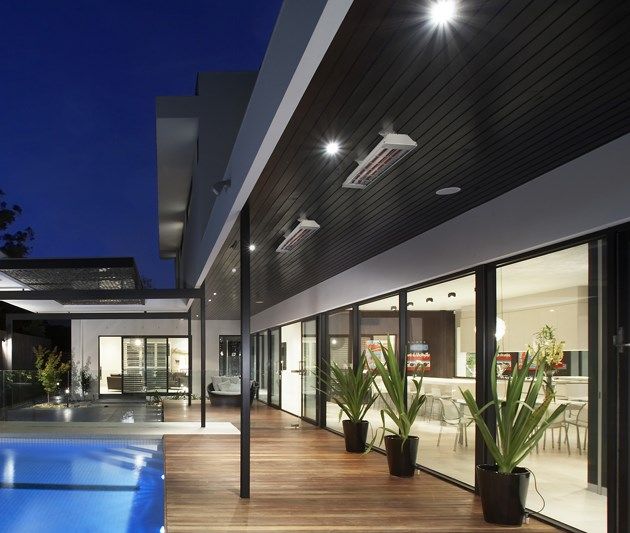
Discrete, stylish heating for undercover outdoor and indoor open areas
Using the radiant heating principle, HEATSTRIP can provide effective and energy efficient comfort heating for undercover
outdoor and indoor open areas. HEATSTRIP has successfully enabled many entertainment venues such as restaurants,
pubs and clubs to utilise their outdoor dining areas day and night, through all seasons. Within your workplace or business,
HEATSTRIP can provide comfort heating for designated outdoor smoking and leisure areas, as well as for workstation
spot heating in factories, warehouses and showrooms. Within your home, HEATSTRIP can provide comfort heating for
undercover alfresco dining and BBQ area, patios, verandas, courtyards and balconies.
There are 3 different series of products within the Heatstrip product category. Each has a different temperature output,
making them ideal for different applications. Below is a list of some common applications, to assist with the selection of the
most effective and efficient series. This is a general guide only, please refer to the Product Manual for each product, for
more information.
HEATSTRIP Design (THH models) is a premium high temperature heater and is primarily used for outdoor rooms
where there is 1,2 3, or 4 enclosed sides, with an ideal mounting height of 2.1 m to 2.7m.
HEATSTRIP Max (THX models) is an ultra high temperature heater used for uncovered or open areas with a
mounting height of 2.4 m to 3.5m.
HEATSTRIP Indoor (THS models) is a medium intensity heater used for protected indoor applications.
APPLICATION THS THH THX
Indoor insulated areas, classrooms, offices, bathrooms, wet areas, drying rooms √ √ X
Outdoor under cover, café, veranda, patio, balcony ceiling height 3m or less X √ X
Outdoor under cover, café, veranda, patio, balcony ceiling height 3m or more X X √
Highly exposed outdoor area X X √
Indoor open area, warehouse, factory, production areas, sports facilities √ √ √
Indoor spot heating, above tables, assembly areas X √ √
3Efficient, cost effective electric heating
The innovative design of the HEATSTRIP enables comfortable and even heat dispersion from the surface with minimal
operating costs.
Design flexibility
Two HEATSTRIP Max models are available, ensuring the heating requirements of any outdoor or open
indoor area is possible. Brackets for direct ceiling or wall/ceiling angled mounting are supplied as standard.
Optional HEATSTRIP accessories include extension mount brackets, twin mount brackets and end to end mounting
brackets.
Minimal maintenance
The HEATSTRIP Max incorporates no internal moving parts ensuring quiet and virtually maintenance free operation.
Australian made
Designed, engineered and assembled in Australia
Easy to use
The standard HEATSTRIP Max is controlled by a simple on/off operation, either when plugged directly into a power point,
or hard-wired via a wall mounted on/off switch. The unit takes approximately 5 minutes to heat up to maximum
temperature and approximately 30 minutes to cool down, depending upon the ambient temperature. Please don’t forget to
turn it off.
4Specifications
MODEL POWER CURRENT DIMENSIONS WEIGHT LEAD PLUG
(WATTS) (AMPS) (mm) (Kg) LENGTH
(mm)
THX2400UK 2400 @ 240 v 10 854 x 170 x 80 5 1000 YES
THX3600UK 3600 @ 240 v 15 1184 x 170 x 80 6 1000 NO
THX2400EU 2400 @ 230 v 10 854 x 170 x 80 5 1000 YES
THX3600EU 3600 @ 230 v 15 1184 x 170 x 80 6 1000 NO
MODEL
HEATER TYPE High intensity electric radiant overhead heater with Incoloy 840 element
OUTPUT Refer to model code chart above
POWER 230-240 Volts Nominal at 50—60 Hertz, Single Phase
CONNECTION 3 Core Cable 2.5mm2
APPROVALS AUSTRALIA/CE
MOUNTING HEIGHT MINIMUM 2.1 m
RECOMMENDED 2.4 m to 3.5 m
MAXIMUM 3.5 m (For higher ceiling heights, units can be
lowered using optional bracket kits or refer to the
Heatstrip Max range)
MOUNTING OPTIONS Suitable for ceiling, wall, beam mounting. Also available for extension
mount using rigid fixing poles and chain mount bracket.
PROTECTION RATING IPX5 Protection from water ingress from all directions
COUNTRY OF MANUFACTURE Australia
THX2400
85
4
11
80
80
THX3600 0
80
17
0
17
5Spot heating principle
In most outdoor or difficult-to-heat indoor applications, therefore are 2 options when looking at the size and quan-
tity of the heater required. Option 1 is to comfort heat the entire area based on the total dimensions of the space,
regarding of whether the entire area is being fully occupied. Option 2 is to spot heat the high use areas, such as
over outdoor tables, BBQ’s, lounges, assembly lines or indoor workstation.
Often it is more practical and efficient to spot heat these areas. Spot heating will help to reduce the initial capital
cost, as well as the running costs. Spot heating will allow the area to be “zoned”, meaning heating only the areas
that are being used, such as tables in a restaurant or outdoor alfresco area.
The top table shows how HEATSTRIP Max can be used over a table.
The bottom table shows the flexibility of using HEATSTRIP to provide a comfortable environment, even when the
layout of the area is very unusual.
THX2400
THX3600
BBQ
BAR
BAR STOOLS
LOUNGE
DINING TABLE
6Radiant footprint
HEATSTRIP Max electric heater produce radiant heat, which heats objects rather than the air. Therefore, it is imperative
that objects to be heated (ie. People), are within the direct radiant footprint of the heater.
The diagram below shows the radiant footprint of HEATSTRIP Max, and is an approximate guide based on a fully
enclosed, outdoor environment.
This diagram shows that the maximum heat output is found directly under the heater, and the temperature decreases as
you move away from the heater.
It highlights the importance of maintaining recommended mounting heights, and positioning the heater directly above the
area to be heated, if possible.
Also, the temperature (ie. surface temperature) is the same for both models, regardless of the wattage. However, the size
increases and the length of the unit increases, the radiant footprint will be larger.
THX RADIANT SECTIONAL AREA
25°C 23°C 21°C
7Selection guide
Prior to selecting the exact model and quantity required for your application, please ensure the correct range of Heatstrip
heaters is being used.
Below is an overview of the Heatstrip options.
HEATSTRIP Design (THH models) is a premium high temperature heater and is primarily used for outdoor rooms
where there is 1,2 3 or 4 enclosed sides, with an ideal mounting height of 2.1 m to 2.7m. Ideal for hard to heat indoor ap-
plications or moist environments where an IP55 rating is required.
HEATSTRIP Max (THX models) is an ultra high temperature heater used for uncovered or open areas with a
mounting height of 2.4 m to 3.5m. Also suitable for difficult indoor environments such as showrooms, production lines,
warehouses etc.
HEATSTRIP Indoor (THS models) is a medium intensity heater used for protected indoor applications, such as
sunrooms, school classrooms, halls, gymnasiums etc.
General recommendations for HEATSTRIP Max:
Ideal mounting height: 2.4m to 3.5m. Maximum is 3.5m in a protected outdoor environment.
Ideal mounting location: ceiling mounted, directly above area to be heated (eg. above a table)
Based on the radiant footprint of the previous page, for a protected outdoor area, a minimum of 250W/m2 is re-
quired. For indoor spot heating, a minimum heating capacity of 150W/m2 is recommended.
The below table outlines the coverage of each HEATSTRIP Max model (in m2), based on 3 different scenarios.
For example, for an outdoor area that is protected from prevailing winds by walls, café blinds etc, Model THX2400 will
cover 9.5m2 and Model THX3600 will cover 14.5m2.
MODEL INDOOR PROTECTED (m2) OUTDOOR ENCLOSED (m2) OUTDOOR EXPOSED (m2)
THX2400 16 9.5 6
THX3600 24 14.5 9
8Installation Requirements
The ideal mounting position for the HEATSTRIP. Max is on the ceiling, directly above the area to be heated. If this is not
possible, HEATSTRIP. Max can be mounted on a wall and angled downwards. In this situation, ensure the mounting
height is in the range of 2.4m to 3.0m and the table is within 3.0m of the wall.
For mounting heights more than 3.5m, we recommend the use of the optional accessories to reduce the height of the
heater to 2.4m—3.5 m. This will increase the effectiveness of your HEATSTRIP. Refer to the Mounting Accessory section
for more information.
Electrical connections/GPO’s should not be located at the back of the heater. They should be located outside the physical
footprint of the units to minimize heat build-up behind the units.
Incorrect Installation Correct Installation
CEILING CEILING
CEILIN
G
CEILING
The heating surface must never be directed toward the ceiling
9Installation location —the below diagrams confirm the minimum recommended clearances.
LIGHT OR SPRINKLER MUST
NOT BE BELOW THE HEATER 300mm MIN.
CEILING
150mm MIN.
1000mm MIN.
150mm MIN.
2100mm MIN.
SURFACE BELOW HEATER
FLOOR
Angled Wall Installation
LIGHT OR SPRINKLER MUST
NOT BE BELOW THE HEATER 300mm MIN.
CEILING
150mm MIN.
150mm MIN.
1000mm MIN.
2100mm MIN.
SURFACE BELOW HEATER
FLOOR
Ceiling Installation
LIGHT OR SPRINKLER MUST
NOT BE BELOW THE HEATER 300mm MIN.
CEILING
150mm MIN.
1000mm MIN.
150mm MIN.
2100mm MIN.
SURFACE BELOW HEATER
FLOOR
Angled Ceiling Installation
10Mounting options
The installation of HEATSTRIP Max is simple and easy with the standard mounting brackets supplied. For other more
challenging locations there are a range of mounting options available - refer to below diagrams.
The HEATSTRIP Max can be mounted directly to the ceiling, angled downwards on a wall, suspended on chains or poles;
attached to beams or poles; or 2 units together. Refer to the following pages for more detailed information on each
mounting option.
CEILING
STANDARD
TWIN MOUNT
BRACKET
BRACKET BEAM MOUNT USING
STANDARD BRACKET
EXTENSION MOUNT
BRACKET
SUSPENSION MOUNT USING
STANDARD BRACKET
STANDARD MOUNTING BRACKETS
INCLUDED IN BOX
END TO END MOUNTING BRACKET
BEAM MOUNT
WITH STANDARD BRACKET
TWIN MOUNTING BRACKETS
EXTENSION MOUNT KIT WITH POLES
SUSPENSION MOUNTING
WITH STANDARD BRACKET
11Standard mounting brackets
The HEATSTRIP Max comes with a pair of standard mounting brackets. These adjustable brackets allow direct ceiling or
wall mount, and come with preset angle options of parallel, 22.5° and 45°.
The flexible standard mounting bracket can be turned 90 degrees to mount onto a beam, it can also be used to suspend
with chains.
The brackets need to be mounted onto a secure frame or wall with a minimum distance between the two brackets. The
minimum distance (“B”) for each model is listed in the table below.
When completing the installation, ensure all screws are tight and unit is secure.
Note: When suspension mounting, chains are not included.
BEAM MOUNTING
CEILING
CEILING MOUNTING
SUSPENSION MOUNTING
WALL MOUNTING
100
80
170
Standard Mounting Bracket
PART No PACKAGED WEIGHT (kg) MATERIALS
DIMENSIONS (mm)
ZBRAK-85 100 x 100 x 25 0.5 316 SS
12MOUNTING
Fix the two mounting brackets to the ceiling or wall in the desired location (refer minimum bracket centre chart).
Make sure the method of fixing (bolts or screws) will be more than strong enough to support weight of heater
allowing for strong winds and other conditions.
Fix the L brackets to the threaded connectors in the required locations on rear of heater to match the centres of
the mounting brackets.
Lift heater into position and secure the mounting brackets to the L brackets using the screws provided.
Locate the C cutout on the L bracket onto the stud in the mounting bracket so you achieve either horizontal or
angle mounting position as required.
Tighten all screws/bolts/nuts.
NOTE: the standard bracket allows for normal or angle mounting of the heater and is suitable for ceiling or wall
mounting.
MODEL “B”
MINIMUM DISTANCE (mm)
THX2400 400
"B
"
THX3600 600
13Flush mount enclosure
The Flush Mount Enclosure is an ideal way to neatly install the HEATSTRIP Max into a ceiling. They are available
for all HEATSTRIP Max models, and are supplied as a one-piece unit for mounting of heaters. Flush mounting can
be used with plaster or wood lined ceiling materials.
An ideal mounting height is 2.4m-3.0m, with a maximum ceiling height of 3.5m in an outdoor environment. Maxi-
mum mounting heights should be strictly followed, otherwise the performance of the units may be reduced.
The facia of the enclosure is manufactured from 316 Stainless Steel and the rear casing is black zinc coated steel.
Please refer to the Installation Manual for more detailed installation information.
SUITABLE FOR MOD- PART No HOLE CUTOUT OVERALL WEIGHT
ELS DIMENSIONS (mm) DIMENSIONS (mm) (kg)
THX2400 THXAC-030 935 x 250 980 x 180 x 290 5
THX3600 THXAC-031 1260 x 250 1310 x 180 x 290 6
14FLUSH MOUNT ENCLOSURE DIMENSIONS
VIEW FROM TOP VIEW FROM UNDERNEATH
236
"B"
35
80
180
Ø8
180
"A"
10
"C"
230
290
PART No MODEL “A” (mm) “B” (mm) “C” (mm)
THHAC-030 THX2400 980 925 920
THHAC-031 THX3600 1310 1250 1245
15INSTALLATION CLEARANCE DIMENSIONS
Shown in the diagrams below are the minimum clearance required for the installation of the Flush Mount
Enclosure.
It is imperative that all cables, backing materials, insulation and other materials are keep clear of the back
and the sides of the Flush Mount Enclosure.
50mm MINIMUM
ROOFING MATERIAL
VIEW FROM SIDE
50mm MINIMUM
CEILING JOIST
BATTEN
50mm MINIMUM
FLUSH MOUNT ENCLOSURE
VIEW FROM ABOVE UNIT
CLEARANCE DIMENSIONS
16INSTALLATION MODEL “D”
DISTANCE FROM END
INSTRUCTIONS TO BRACKET (mm)
THX2400 140
Ensure all minimum clearance requirements are met and the
materials used are compliant to your local building codes. THX3600 305
Before installing the Flush Mount Enclosure ensure the site to be fixed is fully prepared with the hole
cut the correct size and the mounting points securely in place.
HEATER
BRACKET x2
STEP 1: Attach the "D" "D"
brackets to the rear of
the heater. The dimen-
sions for the spacing of
the brackets is listed in
the table.
PLASTER CEILING
FLUSH MOUNT ENCLOSURE
TIMBER BATTEN
STEP 2: Screw the
FME into the battens.
NOTE: screws are not
included.
SCREWS, AT EACH END, THERE ARE 6 HOLES
WITH A DIAMETER OF 8mm EACH
ON
OFF
STEP 3: If there is no
roof access, connect
the heater to the power
source, ensure the
power is OFF.
STEP 4: Lift the heater
into the FME ensuring
the brackets are to the
side of the mounts
STEP 5: Push the
heater to the left ensur-
ing the brackets en-
gage in the mounts. It
will then drop in. Shake
the heater to ensure
that it is securely
mounted. 17Twin mounting bracket
The optional Twin Mount bracket allows for two (2) units of HEATSTRIP
Max to be mounted side-by-side, either in parallel or angled as per the
diagram on the right. This is ideal for applications when a wider heat
coverage is required, or when there is mounting restrictions/limitations
(such as running between 2 rows of tables etc.)
PART No PACKAGED WEIGHT MATERIALS
DIMENSIONS (mm) (kg)
THXAC-018 220 x 100 x 25 1 316 SS
18End to end mounting bracket
The end to end bracket allows multiple units to be joined in a straight line for maximum heat performance
and aesthetic appeal. This is ideal for applications such as long rows of tables and assembly lines, where a
constant heat coverage is required.
The bracket allows for a 50mm gap between units and an opening for the power connection. As per the dia-
gram below, units should be mounted with the power leads together.
The end to end bracket can be used with either the standard ceiling/wall mount bracket or the extension
bracket & pole kit.
PART No PACKAGAED WEIGHT MATERIALS
DIMENSIONS (mm) (kg)
THXAC-019 260 x 50 x 50 0.5 316 SS
19Extension Mount Bracket
The Extension Mount bracket allows HEATSTRIP Max units to be lowered from high ceilings, using rigid con-
nections. The brackets are for use with 25mm x 25mm x 1mm tube (SHS), supplied as a complete kit with
brackets, pre-cut poles and connections. The standard length options as part of the kit are 300mm, 600mm,
900mm and 1200mm.
The kits include all brackets, poles and screws necessary for connection to the heaters, however it does not
include screws for attachment to the ceiling.
*screws to ceiling are not included
300
388
600
688
300
900 388
600988
688
1288
1200
900
PART No PACKAGED WEIGHT MATERIALS NOTES
DIMENSIONS (mm) (kg)
THHAC-005 300 x 150 x 50 2 316 SS Kit includes 2x300mm extension pole, screws
and brackets
THHAC-006 600 x 150 x 50 2 316 SS Kit includes 2x600mm extension pole, screws
and brackets
THHAC-007 900 x 150 x 50 2.5 316 SS Kit includes 2x900mm extension pole, screws
and brackets
THHAC-008 1200 x 150 x 50 3 316 SS Kit includes 2x1200mm extension pole, screws
and brackets
20Wall Controller with remote control
This controller is a custom designed and manufactured
controller for HEATSTRIP . It has been designed for ease
of use to ensure economic running costs of your heater. It
provides a timer for automatic heater operation.
The timer function has four settings. It can turn the heater
on for 1 hour, 2 hours, 4 hours or constantly on.
The timer can be operated where it is installed or via
remote control unit. It has pre set timing for 1 hour, 2 hours
or hours or continuous, allowing the heater to operate
continuously.
The remote control has a range of 10 metres and must be
within line of sight of the wall switch.
Controlling multiple units
It is possible to use one wall controller to control multiple heaters up to 16 Amps load. The wall controller is rated at 16
Amps and 220-240 volts. For larger current draw, it is recommended that you talk to your electrician who can use a
relay to connect more units.
Mounting
The TT-MTR is designed to fit into a standard European wall gangbox. It will just as easily fit into a plaster wall. Your
electrician can install this device.
The controller needs to be installed according to your local wiring guidelines.
Operation
Press “ON/OFF” button to turn power on and off.
Press “TIMER” button to set timer to 1, 2, 4 hours operation. The timer indicator light will show which time setting is
selected. The timer will start the heater and automatically turn it off at the preselected time.
Safety
The TT-MTR controller must be installed in a dry location. It is not suitable for installation where rain or water could
affect the unit..
Ensure the connections are properly connected.
This appliance is not intended for use by persons (including children) with reduced physical, sensory or intellectual
capabilities, or lack of experience and knowledge, unless they have been given supervision or instruction concerning
use of the appliance by a person responsible for their safety. Children should be supervised to ensure they do not play
with the appliance.
Maintenance
The TT-MTR Controller is made from durable materials, however regular care and maintenance of your controller will
help prolong the life of the product.
It is recommended that you dust the controller to keep the surface clean. The cleaning process at least every three
months will reduce the amount of build up and keep it looking as best it can.
Do not use any abrasive materials or products to clean the controller, this includes solvents, citrus based cleaners or
other harsh cleaning products. Do not use water or a damp cloth to clean the controller.
When handling the controller, ensure that your hands are clean or that you use clean gloves as grease or dirt can mark
the surface of the controller.
MODEL MAXIMUM MAXIMUM PACKAGED WEIGHT (kg)
VOLTAGE (Volts) CURRENT (Amps) DIMENSIONS (mm)
TT-MTR 220—240 16 80 x 80 x 42 0.5
21WALL CONTROLLER INSTALLATION
WALL
SCREW
TT-MTR
GANG BOX
22Safety
HEATSTRIP Max has an IP rating of X5. This means it is safe for water ingress from all directions. The HEATSTRIP can
be safely hosed down.
HEATSTRIP Max has undergone extensive testing both in laboratory conditions; in Thermofilm’s manufacturing facility in
Melbourne and field trials in Australia, Europe and overseas. It has been this testing that gives the purchaser the
confidence of a high quality product.
Independent laboratory testing has confirmed full compliance with Australian and other International Standards. This
includes CE, AS/ANZ, UL/CSE
The heater comes in both plug (2400W) and hardwired (3600W) versions. In both cases the fixed wiring must be installed
by a licensed electrician in accordance with the relevant wiring regulations.
HEATSTRIP Max is Class 1 equipment and must be earthed.
In operation, this heater is VERY HOT— do not touch any part of the heater while it is turned on. Do not touch any part
until 30 minutes after it is turned off.
This appliance is not intended for use by persons (including children) with reduced physical, sensory or intellectual
capabilities, or lack of experience and knowledge, unless they have been given supervision or instruction concerning use
of the appliance by a person responsible for their safety. Children should be supervised to ensure they do not play with the
appliance.
Do not allow any cables, furnishings, flammable materials or other items come in contact with any surface of the heater.
If installed in wet areas, the heater switches or controls must be located so that they cannot be touched by persons in the
bath or shower.
The heater needs to be installed as per the installation instructions paying special attention to the minimum clearances.
The heater needs to be mounted on a rigid bracket or fixing.
The heater must not be mounted immediately below or in front of a socket outlet.
In case of a heater fault or damaged supply lead, the appliance should be returned to the point of purchase.
Maintenance
The HEATSTRIP Max is made from durable materials, however regular care and maintenance of your heater will help
prolong the life of the heater.
It is recommended that you hose down the heater and with a soft cloth gently wipe the surfaces of the heater with a mild
detergent to remove the built up contaminants from the environment. Then rinse all detergent off the heater.
All chemicals in the atmosphere including cigarette smoke, pollution etc. will tarnish the surface of the heater. In this case,
additional cleaning and maintenance may be required. The cleaning process at least every three months will reduce the
amount of build up and keep it looking as best it can. If the heater is in a corrosive environment eg. salt spray, we
recommend that you clean your heater with a light spray of fresh water every week. After cleaning, turn the heater on for
20 minutes to dry any water residue and prevent water staining.
Before cleaning or inspection activity, the heater must be switched off and cooled down completely.
Do not use any abrasive materials or products to clean the heater, this includes solvents, citrus based cleaners or other
harsh cleaning products.
When handling the heater, ensure that your hands are clean or that you use clean gloves as grease or dirt can mark the
surface of the heater.
Do not use high pressure water to clean heaters, light water spray only.
23Warranty Terms & Conditions
The below Warranty Terms and Conditions apply for international warranty only.
Cook & Heat B.V. warrants to the original owner that HEATSTRIP Max products will be free from defects in materials and
workmanship for a period of 24 months from the date of purchase in accordance with the following warranty terms and
conditions.
Provision of this warranty is subject to:
The HEATSTRIP product must be installed in accordance with the Installation Instructions and relevant electrical
standards and codes.
The HEATSTRIP product must be maintained and cleaned according to instructions detailed in the Installation Manual.
There is no warranty expressed or implied with regard to capacity requirements. The selection of the unit or units
depends entirely upon the system design and capacities as determined by the purchaser.
The customer has not repaired, opened or altered the product in any unauthorised manner.
This warranty excludes damage to the product or components arising from circumstances outside the control of Cook &
Heat B.V., including, but not limited to, where the product is not used for intended purpose; where the product has
been rectified in any way; incorrect installation; incorrect power supply; damaged caused during delivery; misapplication,
misuse, abuse, vandalism, lack of maintenance or accident.
Cook & Heat’s obligations under this warranty are limited to repair or replacement at Cook & Heat B.V. of any
components of the product which Cook & Heat B.V. identifies to its satisfaction to be defective.
Transportation charges involved in return of the product to Cook & Heat B.V. is the sole responsibility of the customer.
All products are inspected and tested before despatch and are at the risk of the purchaser after the shipment from Cook
& Heat B.V., if not delivered by Cook & Heat B.V. to destination.
Discolouration of the surface may occur after a period of time, this does not constitute a warrantable event.
Twisting and bending of the heaters may occur, this does not constitute a warrantable event.
No products or components will be supplied in advance of an examination of the faulty product or components by Cook &
Heat B.V. or an authorized representative of Cook & Heat B.V.
Cook & Heat B.V. does not participate in any site related costs or labour expenses incidental to replacement of parts,
repairing, removing, installing, servicing, transportation or handling of parts to complete products, and assumes no
liability on parts repaired or replaced without written authorisation. Cook & Heat B.V. shall not be liable for any default or
delay in performance of its warranty obligations caused by any circumstances beyond its control, including, but not
limited to, judicial or government restrictions, strikes, fires, floods, abnormal weather conditions, delayed supply of
components.
Should products be determined as damaged on arrival, immediately notify the transport company of the condition and have
them noted on the freight documents. If damage is discovered after unpacking, demand immediate inspection by the
transportation company and insist that a record of the damage is made on the freight documentation.
The customer warrants using the product in accordance with:
Any instructions provided to it by Cook & Heat B.V. from time to time.
All government and local regulations, including but not limited to all relevant electrical, environmental laws and
regulations governing the installation, storage, use, handling and maintenance of the goods.
All necessary and appropriate precautions and safety measures relating to the installation, storage, use, handling and
maintenance of goods.
DISTRIBUTOR DETAILS FOR
EUROPE & UNITED KINGDOM
Distributed by: Manufactured by:
Cook & Heat B.V. Thermofilm Australia Pty. Ltd.
www.heatstrip.eu 17 Johnston Court
Dandenong South, Victoria, 3175 Australia
24HANDLEIDING VOOR BEDIENING, INSTALLATIE EN ONDERHOUD
H E AT S T R I P M a x
The heater that is a design feature!INHOUDSOPGAVE Rev G Mar16
Productoverzicht ___________________________ 27
Specificaties _______________________________ 29
Puntverwarmingsprincipe _____________________ 30
Straalrichting ______________________________ 31
Keuzegids _________________________________ 32
Installatievereisten __________________________ 33
Montage locatie ____________________________ 34
Montagemogelijkheden ______________________ 35
Standaard montagebeugels ___________________ 36
Montagebehuizing voor inbouw ________________ 38
Afmetingen Flush Mount Enclosure __________ 39
Installatie-afstanden Flush Mount Enclosure ___ 40
Installatie-instructies ______________________ 41
Dubbele montagebeugel ______________________ 42
End to end montageugel ______________________ 43
Verlengde montagebeugel ____________________ 44
Wand controller timer met afstandsbediening ______ 45
Installatie wand controller __________________ 46
Veiligheid en onderhoud ______________________ 47
Algemene voorwaarden garantie _______________ 48
French ____________________________________ 49
German ___________________________________ 73
26Productoverzicht
Heatstrip-heaters voor buitenruimtes of moeilijk te verwarmen binnenruimtes
Omdat er buiten of in open binnenruimtes vaak een constante luchtstroom is, zijn veel terraverwarmers gebaseerd op
convectiewarmte waarmee de lucht verwarmd wordt. Dit kan uitermate onpraktisch zijn voor dit soort locaties, omdat de
verwarmde lucht eenvoudig weggeblazen kan worden door natuurlijke luchtstromen. Straalkachels verwarmen objecten
rechtstreeks door middel van infrarode straling.
Terwijl convectiekachels de lucht tussen objecten verwarmen, verwarmen straalheaters de oppervlakte van de objecten
zelf. HEATSTRIP-straalheaters zijn effectiever in buitenruimtes en niet-geïsoleerde ruimtes omdat ze gericht warmte
afgeven aan de mensen en objecten in hun baan.
Discrete, stijlvolle heater voor overdekte buitenruimtes en open binnenruimtes
Dankzij het straalkachelprincipe kan HEATSTRIP effectieve en energiezuinige comfortverwarming leveren voor
overdekte buitenruimtes en open binnenruimtes. Dankzij HEATSTRIP® kunnen veel uitgaansgelegenheden zoals
restaurants, kroegen en clubs dag en nacht en in alle seizoenen gebruik maken van hun terras. In uw werkplaats of in uw
bedrijf kan HEATSTRIP-comfortverwarming bieden voor aangewezen rookplekken en recreatiegebieden, maar ook
puntverwarming voor werkplaatsen in fabrieken, magazijnen en showrooms. Thuis kan HEATSTRIP-
comfortverwarming bieden onder overkappingen tijdens het buiten eten en barbecueën, of op patio’s, veranda’s,
binnenplaatsen en balkons.
Er zijn drie verschillende productseries in de Heatstrip-productcategorie. Ze hebben elk een verschillende
temperatuuroutput, waardoor ze geschikt zijn voor verschillende toepassingen. Hieronder vindt u een lijst met
veelvoorkomende toepassingen om u te helpen de effectiefste en efficiëntste serie te kiezen. Dit is slechts een algemene
gids; raadpleeg de producthandleiding voor elk product voor meer informatie.
HEATSTRIP Design (THH-modellen) is een premium heater met hoge temperatuur en is vooral bedoeld voor
buitenruimtes met 1, 2, 3 of 4 afgesloten zijden en met een ideale montagehoogte van 2,1 m tot 2,7 m.
HEATSTRIP Max (THX-modellen) is een heater met extreem hoge temperatuur voor niet-overdekte of open gebieden
met een montagehoogte van 2,4 m tot 3,5 m.
HEATSTRIP Indoor (THS-modellen) is een heater met een gemiddelde intensiteit voor toepassingen in beschermde
binnenruimtes.
TOEPASSING THS THH THX
Geïsoleerde binnenruimtes, klaslokalen, kantoren, badkamers, vochtige gebieden, droogruimtes √ √ X
Buiten overdekt, café, veranda, patio, balkon met plafond van 3 m of lager X √ X
Buiten overdekt, café, veranda, patio, balkon met plafond van 3 m of hoger X X √
Zeer open terrein buiten X X √
Open ruimte binnen, magazijn, fabriek, productiefaciliteit, sportfaciliteiten √ √ √
Puntverwarming binnen, boven tafels, montageruimtes X √ √
27Efficiënte, kosteneffectieve elektrische verwarming
Het innovatieve design van de HEATSTRIP zorgt voor een comfortabele en gelijkmatige warmteverspreiding tegen
minimale kosten.
Flexibel design
Er zijn twee HEATSTRIP Max-modellen beschikbaar, zodat voldaan kan worden aan de verwarmingseisen voor elke
buitenruimte of open binnenruimte. Beugels voor montage aan de muur of het plafond worden standaard meegeleverd.
Ook zijn er optionele HEATSTRIP-accessoires, zoals verlengde montagebeugels, dubbele montagebeugels en end-to-end
montagebeugels.
Onderhoudsvriendelijk
De HEATSTRIP Max bevat geen bewegende onderdelen, waardoor de heater vrijwel geluidloos werkt en vrijwel vrij van
onderhoud is.
Geproduceerd in Australië
De HEATSTRIP Max is ontworpen, geproduceerd en geassembleerd in Australië.
Eenvoudig in gebruik
De standaard HEATSTRIP wordt bediend door een eenvoudige aan/uit-schakelaar. De heater kan rechtstreeks op het
stopcontact aangesloten worden of permanent aangesloten worden via een in de muur geplaatste aan/uit-schakelaar. De
unit heeft ongeveer vijf minuten nodig om tot de maximale temperatuur te komen en ongeveer dertig minuten om af te
koelen, afhankelijk van de omgevingstemperatuur. Vergeet niet de unit uit te schakelen.
28Specificaties
MODEL VERMOGEN STROOM AFMETINGEN GEWICHT LENGTE KABEL STEKKER
(WATT) (AMPÈRE) (MM) (KG) (MM)
THX2400UK 2400 @ 240 v 10 854 x 170 x 80 5 1000 JA
THX3600UK 3600 @ 240 v 15 1184 x 170 x 80 6 1000 NEE
THX2400EU 2400 @ 230 v 10 854 x 170 x 80 5 1000 JA
THX3600EU 3600 @ 230 v 15 1184 x 170 x 80 6 1000 NEE
MODEL
TYPE HEATER Hangende elektrische straalheater met hoge intensiteit met Incoloy 840-element
OUTPUT Zie bovenstaande modeltabel
SPANNING 230-240 volt nominaal bij 50-60 Hertz, 1-fase
VERBINDING 3-aderige kabel 2,5 mm2
KEURMERKEN AUSTRALIË/CE
MONTAGEHOOGTE MINIMAAL 2.1 m
AANBEVOLEN 2.4 m to 3.5 m
MAXIMAAL 3.5 m (voor hogere plafonds kunnen units verlaagd
worden met optionele beugelsets of het gamma van
Heatstrip Max)
MONTAGEMOGELIJKHEDEN Geschikt voor montage aan plafonds, muren en balken. Ook geschikt voor
verlengde montage met behulp van stijve bevestigingsbuizen en kettingbeugels.
BESCHERMINGSGRAAD IPX5-bescherming tegen indringing van water uit alle richtingen
LAND VAN HERKOMST Australië
THX2400
85
4
11
80
80
THX3600 0
80
17
0
17
29Puntverwarmingsprincipe
Bij de meeste toepassingen in buitenruimtes of moeilijk te verwarmen binnenruimtes zijn er twee mogelijkheden waar u uit
kunt kiezen wat betreft de grootte en capaciteit van de vereiste heaters. De eerste mogelijkheid is het hele gebied van
comfortwarmte te voorzien op basis van de afmetingen van de ruimte, afhankelijk van of de hele ruimte gebruikt wordt. De
tweede mogelijkheid is om puntverwarming toe te passen bij de gebieden die het meest gebruikt worden, zoals boven
buitentafels, barbecues, loungehoeken, lopende banden of indoor werkplaatsen
Voor dit soort gebieden is puntverwarming vaak praktischer en efficiënter. Puntverwarming zorgt voor lagere
aanschafkosten, maar ook lagere gebruikskosten. Met puntverwarming kunt u de ruimte indelen in zones, wat inhoudt dat
alleen de gebruikte gebieden verwarmd worden, zoals tafels in een restaurant of een buitenterras.
De bovenste afbeeldingen laten zien hoe HEATSTRIP Max boven een tafel gebruikt kan worden.
De onderste afbeelding toont de flexibiliteit van het gebruik van HEATSTRIP Max om een comfortabele omgeving te
creëren, zelfs bij ongewone indelingen.
THX2400
THX3600
BBQ
BAR
BAR STOOLS
LOUNGE
DINING TABLE
30Straalrichting
HEATSTRIP elektrische heaters produceren stralingswarmte, die objecten verwarmt in plaats van de lucht. Het is
daarom van groot belang dat de objecten die verwarmd dienen te worden (bijv. mensen) zich in de straalrichting van de
heater bevinden.
Onderstaand diagram geeft de straalrichting weer van HEATSTRIP Max en is bij benadering een richtlijn, gebaseerd op
een volledig omsloten buitenruimte.
Dit diagram toont aan dat de maximale warmteoutput zich direct onder de heater bevindt en dat deze verder bij de heater
vandaan afneemt.
Hieruit blijkt hoe belangrijk het is dat de aanbevolen montagehoogtes worden opgevolgd en dat de heater recht boven de
te verwarmen locatie wordt gemonteerd (indien mogelijk).
De temperatuur (d.w.z. oppervlaktetemperatuur) is gelijk voor beide modellen, ongeacht het wattage. Naarmate de
afmetingen en lengte van de unit toenemen, wordt de straalrichting echter breder en langer.
THX RADIANT SECTIONAL AREA
25°C 23°C 21°C
31Keuzegids
Voordat u het specifieke model en het aantal heaters voor uw toepassing kiest, dient u er zeker van te zijn dat u de juiste
Heatstrip-serie gebruikt.
Hieronder vindt u een overzicht van de Heatstrip-opties.
HEATSTRIP Design (THH-modellen) is een premium heater met hoge temperatuur en is vooral bedoeld voor
buitenruimtes met 1, 2, 3 of 4 afgesloten zijden, met een ideale montagehoogte van 2,1 m tot 2,7 m. Ideaal voor
toepassing in binnenruimtes die moeilijk te verwarmen zijn of vochtige omgevingen waar een beschermingsgraad van
IP55 vereist is.
HEATSTRIP Max (THX-modellen) is een heater met extreem hoge temperatuur voor onbedekte of open ruimtes met
een montagehoogte van 2,4 m tot 3,5 m. Ook geschikt voor moeilijke binnenruimtes zoals showrooms, productielijnen,
magazijnen, etc.
HEATSTRIP Indoor (THS-modellen) is een heater met een gemiddelde intensiteit voor toepassingen in beschermde
binnenruimtes, zoals serres, klaslokalen, hallen, sporthallen, etc.
Algemene aanbevelingen voor HEATSTRIP Max:
Ideale montagehoogte: 2,4 m tot 3,5 m. Maximaal 3,5 m in een beschermde buitenruimte.
Ideale montagelocatie: plafond, recht boven het te verwarmen gebied (bijv. boven een tafel).
Gebaseerd op de straalrichting op de vorige pagina, is voor een omsloten buitenruimte minimaal 250 W/m 2
vereist.
Voor indoor spotverwarming is een verwarmingscapaciteit van minimaal 150 W/m2 aanbevolen.
De onderstaande tabel geeft de dekking van elk HEATSTRIP Max-model (in m2) weer, gebaseerd op drie verschillende
scenario’s. Voor een buitengebied afgeschermd van de wind door muren, terraswanden, etc. heeft Model THX2400 een
dekking van 9,5 m2 en Model THX3600 een dekking van 14,5 m2.
MODEL BINNEN BESCHERMD (M2) BUITEN OMSLOTEN (M2) BUITEN OPEN (M2)
THX2400 16 9.5 6
THX3600 24 14.5 9
32Installatievereisten
De ideale montagelocatie voor de HEATSTRIP Max is aan het plafond, recht boven het te verwarmen gebied. Indien dit
niet mogelijk is kan HEATSTRIP Max aan de muur bevestigd worden en naar beneden gericht worden. Zorg er in dit
geval voor, dat de montagehoogte tussen de 2,4 m en 3,0 m ligt en dat de tafel binnen 3,0 m van de muur staat.
Voor montagehoogtes hoger dan 3,5 m raden we het gebruik van de optionele accessoires aan om de heater te verlagen
tot 2,4-3,5 m. Dit verhoogt de effectiviteit van uw HEATSTRIP. Zie het hoofdstuk over montageaccessoires voor meer
informatie.
Elektrische aansluitingen/stopcontacten mogen zich nooit achter de heater bevinden. Ze moeten buiten de fysieke locatie
van de heater geplaatst zijn om de opbouw van warmte achter de units te beperken.
Onjuiste installatie Juiste installatie
CEILING CEILING
CEILIN
G
CEILING
PLAFOND
De heater mag nooit naar het plafond gericht worden.
33Montagelocatie — het onderstaande diagram geeft de aanbevolen minimumafstanden weer.
LIGHT OR SPRINKLER MUST
NOT BE BELOW THE HEATER 300mm MIN.
CEILING
150mm MIN.
1000mm MIN.
150mm MIN.
2100mm MIN.
SURFACE BELOW HEATER
FLOOR
Wandmontage schuin
LIGHT OR SPRINKLER MUST
NOT BE BELOW THE HEATER 300mm MIN.
CEILING
150mm MIN.
150mm MIN.
1000mm MIN.
2100mm MIN.
SURFACE BELOW HEATER
FLOOR
Plafondmontage
LIGHT OR SPRINKLER MUST
NOT BE BELOW THE HEATER 300mm MIN.
CEILING
150mm MIN.
1000mm MIN.
150mm MIN.
2100mm MIN.
SURFACE BELOW HEATER
FLOOR
Plafondmontage schuin
34Montagemogelijkheden
Met de standaard bijgeleverde montagebeugels is de HEATSTRIP Max eenvoudig te monteren. Voor andere, moeilijkere
locaties zijn er diverse montagemogelijkheden beschikbaar – zie de onderstaande diagrammen.
De HEATSTRIP Max kan op meerdere manieren bevestigd worden: rechtstreeks aan het plafond, schuin naar beneden
gericht aan de muur, hangend aan kettingen of buizen, bevestigd aan balken of buizen of zelfs twee units naast elkaar. Zie
de volgende pagina’s voor gedetailleerde informatie over elke montagemogelijkheid.
CEILING
STANDARD
TWIN MOUNT
BRACKET
BRACKET BEAM MOUNT USING
STANDARD BRACKET
EXTENSION MOUNT
BRACKET
SUSPENSION MOUNT USING
STANDARD BRACKET
STANDARD MOUNTING BRACKETS
INCLUDED IN BOX
END TO END MOUNTING BRACKET
BEAM MOUNT
WITH STANDARD BRACKET
TWIN MOUNTING BRACKETS
EXTENSION MOUNT KIT WITH POLES
SUSPENSION MOUNTING
WITH STANDARD BRACKET
35Standaard montagebeugels
Bij de HEATSTRIP Max worden twee standaard montagebeugels geleverd. Met deze instelbare beugels kunt u de heater
rechtstreeks aan het plafond of op de muur bevestigen. Deze montagebeugels kunnen standaard parallel of onder een
hoek van 22,5° of 45° worden ingesteld.
De flexibele standaard bevestigingsbeugel kan 90 graden gedraaid worden voor bevestiging aan een balk en kan ook
opgehangen worden met kettingen.
De beugels moeten op een vast frame of muur bevestigd worden met een minimale afstand tussen de twee beugels. De
minimumafstand (“B”) voor elk model staat hieronder vermeld.
Controleer tijdens het afronden van de installatie of alle schroeven goed zijn vastgedraaid en de unit goed vast zit.
Opmerking: bij hangende bevestiging worden de kettingen niet meegeleverd.
BEAM MOUNTING
CEILING
CEILING MOUNTING
SUSPENSION MOUNTING
WALL MOUNTING
100
80
170
Standaard montagebeugel
ONDERDEELNR. AFMETINGEN GEWICHT MATERIALEN
VERPAKKING (MM) (KG)
ZBRAK-85 100 x 100 x 25 0.5 316 SS
36INSTALLATIE
Bevestig de twee montagebeugels op de gewenste plaats aan het plafond of op de muur (zie de tabel voor
minimumafstand tussen de middelpunten van de beugels). Zorg ervoor dat de bevestigingsmethode (bouten of
schroeven) stevig genoeg is om het gewicht van de heater te dragen en houd rekening met harde wind en
andere omstandigheden.
Bevestig de L-beugels op de van schroefdraad voorziene verbindingspunten op de vereiste plaatsen aan de
achterkant van de heater zodat ze overeenkomen met de middelpunten van de montagebeugels. Til de heater
naar de juiste positie en bevestig de montagebeugels met de bijgeleverde schroeven aan de L-beugels. Plaats de
C-uitsparing van de L-beugel op het uitsteeksel van de montagebeugel voor horizontale of schuine positie.
Draai alle schroeven/bouten/moeren stevig vast.
OPMERKING: de standaard montagebeugel is geschikt voor normale of schuine bevestiging van de heater aan
het plafond of op de muur.
MODEL “B” MINIMUMAFSTAND (MM)
THX2400 400
"B
"
THX3600 600
37Montagebehuizing voor inbouw (FME)
De montagebehuizing voor inbouw is (Flush Mount Enclosure FME) de ideale manier om de Heatstrip Max netjes in
het plafond te plaatsen. Het is beschikbaar voor alle Heatstrip Max-modellen en wordt geleverd als een uit één stuk
bestaande unit voor het monteren van heaters. Inbouw kan gebruikt worden bij stucwerk of met hout beklede pla-
fonds.
De ideale montagehoogte is 2,4 m tot 3,5 m, met een maximale plafondhoogte van 3,0 m in een buitenruimte. In-
dien de maximale montagehoogte wordt overschreden, kan dit ten koste gaan van de prestaties van de unit.
De voorzijde van de inbouwbehuizing is gemaakt van 316 roestvrij staal en de achterzijde is gemaakt van zwart
verzinkt staal. Meer details over installatie-instructies vindt u in de installatiehandleiding
SUITABLE FOR MOD- PART No HOLE CUTOUT OVERALL WEIGHT
ELS DIMENSIONS (mm) DIMENSIONS (mm) (kg)
THX2400 THXAC-030 935 x 250 980 x 180 x 290 5
THX3600 THXAC-031 1260 x 250 1310 x 180 x 290 6
38Afmetingen Flush Mount Enclosure
VIEW FROM TOP
Bovenaanzicht VIEW FROM UNDERNEATH
Onderaanzicht
236
"B"
35
80
180
Ø8
180
"A"
10
"C"
230
290
PART No MODEL “A” (mm) “B” (mm) “C” (mm)
THHAC-030 THX2400 980 925 920
THHAC-031 THX3600 1310 1250 1245
39Installatie-afstanden Flush Mount Enclosure
In onderstaand schema zijn de minimale afstanden getoond die nodig zijn voor het installeren
van de Flush Mount Enclosure.
Het is noodzakelijk dat alle kabels, dragers, isolatie en andere materialen vrij blijven van de
achterkant en de zijkanten van de Flush Mount Enclosure.
50mm MINIMUM
ROOFING MATERIAL
VIEW FROM SIDE
50mm MINIMUM
CEILING JOIST
BATTEN
50mm MINIMUM
FLUSH MOUNT ENCLOSURE
VIEW FROM ABOVE UNIT
CLEARANCE DIMENSIONS
40Installatie-instructies MODEL “D”
DISTANCE FROM END
Zorg ervoor dat aan alle minimale afstands-vereisten is TO BRACKET (mm)
voldaan en de gebruikte materialen voldoen aan uw lokale
THX2400 140
bouwvoorschriften.
Voordat u de Flush Mount Enclosure bevestigt, dient de mon-
THX3600 305
tageplaats voorbereid te zijn: het gat moet in het juiste formaat
zijn aangebracht en de bevestigingspunten moeten goed vast
zitten.
STAP 1: Bevestig de HEATER
beugels aan de achterkant BRACKET x2
van het verwarmingsele-
ment. De maten voor de "D" "D"
ruimte tussen de beugels
staan vermeld in de tabel.
PLASTER CEILING
FLUSH MOUNT ENCLOSURE
TIMBER BATTEN
STAP 2: Schroef de Flush
Mount Enclosure vast.
LET OP: schroeven worden
niet meegeleverd.
SCREWS, AT EACH END, THERE ARE 6 HOLES
WITH A DIAMETER OF 8mm EACH
ON
STAP 3: Als er geen toe- OFF
gang is van bovenaf, sluit
dan het verwarmingsele-
ment aan op het el-
ektriciteitsnet en zorg ervoor
dat de elektriciteit UITGE-
SCHAKELD is.
STAP 4: Plaats het verwar-
mingselement in de Flush
Mount Enclosure ervoor
zorgend dat de beugels
naast de bevestigings-
punten zitten.
STAP 5: Druk het verwar-
mingselement naar links en
zorg ervoor dat de beugels
in de bevestigingspunten
vallen. Het verwarmingsele-
ment zakt er dan in. Schud
aan het verwarmingsele-
ment om te controleren of
deze stevig vast zit 41Dubbele montagebeugel
Met de optionele dubbele montagebeugel kunnen twee HEATSTRIP
Max-units parallel of schuin naast elkaar bevestigd worden, zoals in het
diagram rechts. Dit is ideaal voor toepassingen waar meer
warmtedekking vereist is of indien er beperkingen zijn omtrent de
installatie (zoals tussen twee rijen tafels, etc.).
ONDERDEELNR. AFMETINGEN GEWICHT MATERIA-LEN
VERPAKKING (MM) (KG)
THXAC-018 220 x 100 x 25 1 316 SS
42End-to-end montagebeugel
Met de end-to-end beugel kunnen meerdere units in een rechte lijn verbonden worden voor maximale
warmte en een aantrekkelijk design. Dit is ideaal voor lange rijen tafels of lopende banden, waar een
constante warmtedekking vereist is.
Met de beugels kunnen units 50 mm uit elkaar geplaatst worden met een opening voor de stroomtoevoer.
Zoals in onderstaand diagram vermeld is, dienen de units met de stroomsnoeren bij elkaar gemonteerd te
worden.
De end-to-end beugel kan gebruikt worden met de standaard montagebeugel voor plafonds en muren of de
kit met verlengde beugel en buis.
ONDERDEELNR. AFMETINGEN GEWICHT MATERIALEN
VERPAKKING (MM) (KG)
THXAC-019 260 x 50 x 50 0.5 316 SS
43Verlengde montagebeugel
)
Met de verlengde montagebeugel kunnen HEATSTRIP® Max-units met stijve verbindingen verlaagd worden
bevestigd aan hoge plafonds. De beugels zijn geschikt voor gebruik met 25 x 25 x 1 mm buizen (SHS) en worden
geleverd als een complete kit met beugels, voorgesneden buizen en verbindingen. De standaardlengtes in de kit zijn
300 mm, 600 mm, 900 mm en 1200 mm.
De kits bevatten alle beugels, buizen en schroeven die nodig zijn voor verbinding met de heaters, maar worden
geleverd zonder schroeven voor bevestiging aan het plafond.
300
388
600
688
300
900 388
600988
688
1288
1200
900
ONDERDEELNR. AFMETINGEN GEWICHT MATERIALEN OPMERKINGEN
VERPAKKING (MM) (KG)
THHAC-005 300 x 150 x 50 2 316 SS Kit bevat 2 x 300 mm verlengbuis, schroeven en
beugels
THHAC-006 600 x 150 x 50 2 316 SS Kit bevat 2 x 600 mm verlengbuis,
schroeven en beugels
THHAC-007 900 x 150 x 50 2.5 316 SS Kit bevat 2 x 900 mm verlengbuis,
schroeven en beugels
THHAC-008 1200 x 150 x 50 3 316 SS Kit bevat 2 x 1200 mm verlengbuis,
schroeven en beugels
44TT-MTR wandcontroller met afstandsbediening
Deze controller is speciaal ontworpen en vervaardigd
voor HEATSTRIP. Daarmee is optimaal gebruiksgemak en
zuinig verbruik van uw verwarmer gegarandeerd. De
timerfunctie zorgt voor automatische werking van de
verwarmer en biedt vier standen: voor 1 uur, 2 uur, 4 uur
of permanente werking. De timer is te bedienen op de
plaats waar hij is geïnstalleerd of via afstandsbediening.
De voorgeprogrammeerde tijdinstellingen zijn voor 1 uur,
2 uur of 4 uur of permanente werking van de verwarmer.
De afstandsbediening heeft een bereik van 10 meter en
moet zich in het zicht van de wandschakelaar bevinden.
Meerdere units bedienen
Met één wandcontroller is het mogelijk meerdere
verwarmers te bedienen tot een maximale belasting van 16 A. De wandcontroller is geschikt voor 16 A en 220-240 Volt.
Voor hogere stroomopname adviseren wij uw elektricien in te schakelen om een relais te installeren dat meerdere units
verbindt.
Montage
De TT-MTR is ontworpen voor installatie in een standaard Europese wandverbindingsdoos. Ook inbouwmontage in de
wand is mogelijk. Uw elektricien kan dit apparaat installeren.
De controller dient geïnstalleerd te worden volgens uw lokale bedradingsrichtlijnen.
Bediening
Druk op de 'ON/OFF'-toets om het apparaat aan en uit te schakelen.
Druk op de 'TIMER'-toets om de timer in te stellen op een werkingsduur van 1, 2 of 4 uur. Het timerindicatielampje
geeft aan welke tijdinstelling is geselecteerd. De timer start de verwarmer en schakelt deze automatisch uit als de
vooraf ingestelde tijd is verstreken.
Veiligheid
De TT-MTR controller moet worden geïnstalleerd op een droge plaats. Hij is niet geschikt voor installatie op een plaats
waar de unit in aanraking kan komen met regen of water.
Zorg dat de aansluitingen correct zijn verbonden.
Dit apparaat is niet bedoeld voor gebruik door personen (inclusief kinderen) met verminderde fysieke, sensorische of
intellectuele capaciteiten, of met gebrek aan ervaring en kennis, tenzij dat onder toezicht gebeurt of ze geïnstrueerd
zijn over het gebruik van dit apparaat door een persoon die verantwoordelijk is voor hun veiligheid. Houd toezicht op
kinderen om ervoor te zorgen dat ze niet met het apparaat spelen.
Onderhoud
De TT-MTR Controller is gemaakt van duurzame materialen, maar regelmatige verzorging en onderhoud van uw
controller helpt de levensduur van het product te verlengen.
Stof de controller regelmatig af om het oppervlak schoon te houden. Door dit minimaal elke drie maanden te doen
verzamelt zich minder vuil en blijft het apparaat er optimaal uitzien.
Gebruik voor het reinigen van de controller geen schurende materialen of producten, inclusief oplosmiddelen, op citrus
gebaseerde reinigingsmiddelen of andere agressieve reinigingsproducten. Gebruik geen water of een vochtige doek om
de controller te reinigen.
Zorg dat bij het bedienen van de controller uw handen schoon zijn of dat u handschoenen draagt, omdat vet en vuil het
oppervlak aantasten.
MODEL MAXIMALE MAXIMALE VERPAKKINGS- GEWICHT
VOLTAGE (Volts) AMPÈRES (Amps) AFMETINGEN (mm) (kg)
TT-MTR 220—240 16 80 x 80 x 42 0.5
45Installatie wand controller
WALL
SCREW
TT-MTR
GANG BOX
46Veiligheid
HEATSTRIP Max beschikt over beschermingsgraad IPX5. Dit houdt in dat de unit beschermd is tegen indringing van water vanuit alle
richtingen. De HEATSTRIP kan zonder problemen schoongemaakt worden.
HEATSTRIP is uitgebreid getest in laboratoria, de fabriek van Thermofilm in Melbourne en in de praktijk in Australië en daarbuiten.
Dankzij al deze testen is de klant verzekerd van een product van zeer hoge kwaliteit.
Onafhankelijk laboratoriumonderzoek bevestigt volledige compliance met Australische en andere internationale standaarden, zoals CE,
AS/ANZ en UL/CSE.
De heater is leverbaar als uitvoering met stekker (2400 W) en als uitvoering voor aansluiting op het vaste stroomnet (3600 W). Bij beide
uitvoeringen dient de vaste bedrading door een erkende elektricien geïnstalleerd te worden met inachtneming van relevante wet- en
regelgeving.
HEATSTRIP is Klasse 1-apparatuur en moet geaard zijn.
Als de heater is ingeschakeld, wordt hij ZEER HEET. Raak geen enkel onderdeel van de heater aan als deze is ingeschakeld. Raak geen
enkel onderdeel aan tot dertig minuten nadat de heater is uitgeschakeld.
Dit apparaat is niet bedoeld voor gebruik door personen (waaronder kinderen) met verminderde lichamelijke, zintuiglijke of
verstandelijke vermogens of door personen met een gebrek aan ervaring en kennis, tenzij zij onder toezicht staan van of instructies
ontvangen over het gebruik van het apparaat van een persoon die verantwoording draagt voor hun veiligheid. Kinderen dienen in de gaten
gehouden te worden om ervoor te zorgen dat zij niet met het apparaat spelen.
Voorkom dat kabels, meubilair, brandbare materialen of andere items in contact komen met de oppervlakte van de heater.
Indien geïnstalleerd in een vochtige ruimte dienen de schakelaars of regelaars van de heater buiten het bereik van personen in bad of
onder de douche geplaatst te worden.
De heater dient volgens de installatievereisten geplaatst te worden, met name wat betreft de minimumafstanden.
De heater dient op een stijve beugel of bevestigingspunt bevestigd te worden.
De heater dient niet recht onder of voor een stopcontact bevestigd te worden.
In het geval van een kapot of beschadigd stroomsnoer dient het apparaat teruggebracht te worden naar de winkel waar het gekocht.
Onderhoud
De HEATSTRIP Max is gemaakt van duurzame materialen, maar regelmatig onderhoud kan de levensduur van uw heater
verlengen.
Wij raden u aan de heater af te spoelen en de oppervlaktes van de heater met een droge doek met een mild schoonmaakmiddel
schoon te maken om opgehoopt vuil te verwijderen. Spoel de heater vervolgens af en zorg dat er geen resten van het
schoonmaakmiddel achterblijven.
Chemische stoffen in de lucht, waaronder sigarettenrook, luchtvervuiling, etc., beschadigen de oppervlakte van de heater. In dit
geval is extra schoonmaak en onderhoud mogelijk vereist. Door de heater ten minste elke drie maanden schoon te maken,
wordt ophoping tegengegaan en blijft de heater mooi. Indien de heater zich in een corrosieve omgeving bevindt, bijv. omdat
deze in aanraking kan komen met zout, raden wij u aan de heater elke week schoon te maken door er zoet water op te sprayen.
Schakel de heater na het schoonmaken twintig minuten in om eventuele waterresten te laten drogen en watervlekken te
voorkomen.
Voordat u de heater gaat schoonmaken of inspecteren, dient de heater volledig uitgeschakeld en afgekoeld te zijn. Gebruik
geen schuurmiddelen of -producten om de heater schoon te maken, zoals oplosmiddelen, schoonmaakmiddelen op citrusbasis
of andere ruwe schoonmaakproducten.
Zorg ervoor dat uw handen schoon zijn tijdens het bedienen van de heater of trek handschoenen aan, omdat vet en vuil de
oppervlakte van de heater kunnen beschadigen. Gebruik geen hogedrukreinigers om de heater schoon te maken; gebruik alleen
fijne waterspray.
47You can also read