HOUSEHOLD DISHWASHERS - Availability of spare parts and Repair and Maintenance Information
←
→
Page content transcription
If your browser does not render page correctly, please read the page content below
Availability of spare parts and Repair and Maintenance Information

            HOUSEHOLD
                                Bezpečnost

           DISHWASHERS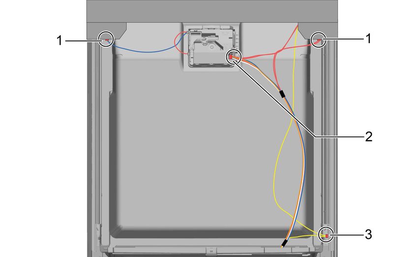
Availability of spare parts
Bezpečnost

The following spare parts can be ordered by professional repair shops at this email
address: info@awservice.cz, with the subject of the message „Spare parts order (a)“

motor;
circulation and drain pump;
heaters and heating elements, including heat pumps (separately or bundled);
piping and related equipment including all hoses, valves, filters and aquastops;
structural and interior parts related to door assemblies (separately or bundled);
printed circuit boards;
electronic displays;
pressure switches;
thermostats and sensors;
software and firmware including reset software;

In the e-mail message attach a photo of the rating label of the product for which you are
ordering a spare part, the name of the spare part and the number of ordered units.

The following spare parts can be ordered by professional repair shops and end users
at this email address: info@awservice.cz, with the subject of the message „Spare parts
order (b)“

door hinge and seals, other seals, spray arms, drain filters, interior racks and plastic
peripherals such as baskets and lids;

In the e-mail message attach a photo of the rating label of the product for which you are
ordering a spare part, the name of the spare part and the number of ordered units.
Maintenance Information - D1
Model D1, EAN: 4251539600339, Serial number: 1xxxxxxxxx21153960033x

     Important information                                                   4.8.1   Removing detergent cover
1.1 Important information                                                    4.8.2   Inserting spring
    1.1.1                                                                    4.8.3   Installing detergent cover
            Purpose
1.2 Explanation of symbols                                            4.9    Replacing wastewater pump cover
    1.2.1                                                                    4.9.1   Removing wastewater pump cover
            Danger levels
    1.2.2                                                                    4.9.2   Installing wastewater pump cover
            Hazard symbols
    1.2.3                                                             4.10   Replacing side panel
            Structure of the warnings
    1.2.4                                                                    4.10.1 Removing side panel
            General symbols
                                                                             4.10.2 Installing side panel
     Safety                                                           4.11   Replacing outer door
2.1 General Safety instructions                                              4.11.1 Removing outer door
    2.1.1                                                                    4.11.2 Installing outer door
            All domestic appliances
                                                                      4.12   Replacing control panel
     Tools and aids                                                          4.12.1 Removing control panel
                                                                             4.12.2 Installing control panel
     Repair                                                           4.13   Fix door springs
4.1 Replacing worktop                                                 4.14   Replacing toe panel
    4.1.1                                                                    4.14.1 Removing toe panel
              Removing worktop
    4.1.2                                                                    4.14.2 Installing toe panel
              Installing worktop
4.2 Installing basket system                                          4.15   Replacing base socket plate
    4.2.1                                                                    4.15.1 Removing base socket plate
              Installing a tab slide for the 86 cm model
    4.2.2                                                                    4.15.2 Installing base socket plate
              Installing cup support clip
    4.2.3                                                             4.16   Replacing overflow conduit
              Installing steamer insert
4.3 Replacing varioDrawer                                                    4.16.1 Removing overflow channel
    4.3.1                                                                    4.16.2 Installing overflow conduit
              Removing varioDrawer
    4.3.2                                                             4.17   Replacing inner door
              Installing varioDrawer
4.4 Replacing spray arms                                                     4.17.1 Removing inner door
    4.4.1                                                                    4.17.2 Installing inner door
              Removing spray arm
    4.4.2                                                             4.18   Replacing door hinge
              Installing spray arm
4.5 Replacing filters                                                        4.18.1 Removing door hinge
    4.5.1                                                                    4.18.2 Installing door hinge
              Removing filter
    4.5.2                                                             4.19   Replacing (lower) door seal
              Installing filters
4.6 Installing baking sheet spray head                                       4.19.1 Removing the door seal
4.7 Replacing power cord                                                     4.19.2 Installing the door seal
    4.7.1                                                             4.20   Replacing (upper) door seal
              Unplugging power cord
    4.7.2                                                                    4.20.1 Removing door seal
              Plugging in power cord
4.8 Replacing detergent cover                                                4.20.2 Installing door seal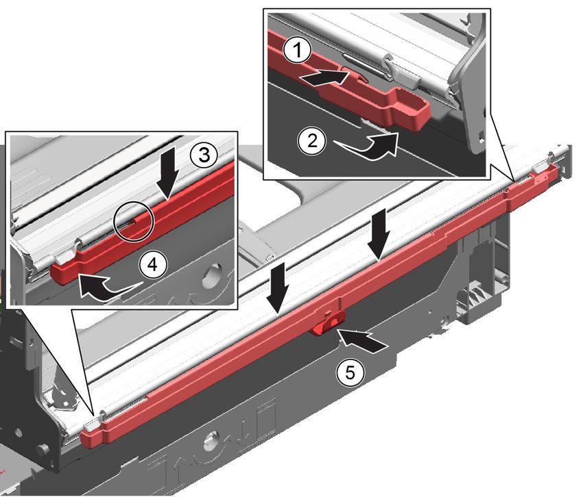
Maintenance Information - D1

4.21 Replacing EmotionLight
     4.21.1 Removing EmotionLight
4.21.2 Installing EmotionLight
4.22 Replacing TimeLight
     4.22.1 Removing TimeLight
     4.22.2 Installing TimeLight
4.23 Replacing Gap illumination
     4.23.1 Removing Gap illumination
     4.23.2 Installing Gap illumination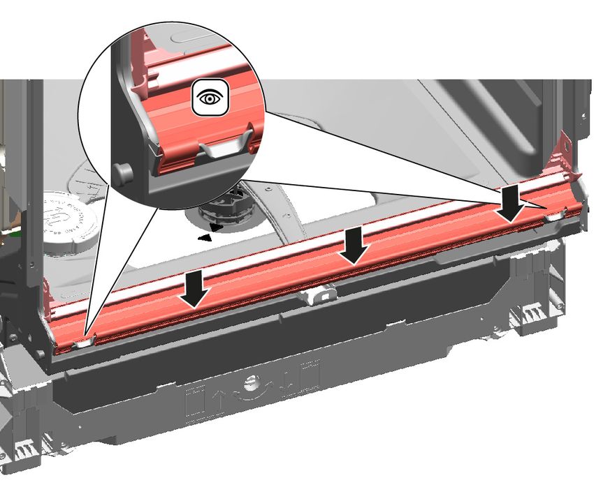
Important information
Concerning this document

1.1 Important information                                                               1.2 Explanation of symbols
1.1.1 Purpose                                                                           1.2.1 Danger levels
These repair hints support consumer to repair appliances by himself according to the    The warning levels consist of a symbol and a signal word. The signal word indicates
applicable eco-design regulation (as of 03/2021).                                       the severity of the danger.
They contain information how to exchange defined spare parts including warnings and                   Warning level                 Meaning
risks.
In case of questions, please contact our customer service. We will only be liable for                                               Non-observance of the warning message
                                                                                                       Danger                       will result in death or serious injuries.
damages if the repair hints have been followed properly.
                                                                                                                                    Non-observance of the warning message
                                                                                                       Warning                      could result in death or serious injuries.
                                                                                                                                    Non-observance of the warning message
                                                                                                       Caution                      could result in minor injuries.
                                                                                                      Notice                        Non-observance of the warning message
                                                                                                                                    could result in damage to property.
                                                                                        Table 1: Danger levels

                                                                                        1.2.2 Hazard symbols
                                                                                        Hazard symbols are symbolic representations which give an indication of the kind of
                                                                                        danger.
                                                                                        The following hazard symbols are used in this document:
                                                                                                     Hazard symbol                  Meaning
                                                                                                                                    General warning message

                                                                                                                                    Danger from electrical voltage

                                                                                                                                    Risk of explosion

                                                                                                                                    Danger of cuts

                                                                                                                                    Danger of crushing
Important information

             Hazard symbol                 Meaning                                        Gen. symbol                Meaning
                                           Danger from hot surfaces                                                  Identification of required tools
                                                                                                                     Identification of required preconditions
                                                                                                                     Identification of a condition (if ..., then ...)
                                           Danger from strong magnetic field
                                                                                                                     Identification of a result
                                                                                           Start                     Identification of a key or button
                                           Danger from non-ionizing radiation             [00123456]                 Identification of a material number
                                                                                          Status                     Identification of displayed text / window
                                                                                                                     (in the appliance's display)
Table 2: Hazard symbols                                                                   Table 3: General symbols

1.2.3 Structure of the warnings
Warnings in this document have a standardised appearance and a standardised struc-
ture.

                             Danger
             Type and source of danger!
             Possible consequences of ignoring the danger / warning.
               ▶ Measures and prohibitions for preventing the danger.
The following example shows a warning that warns against electric shock due to live
parts. The measure for avoiding the danger is mentioned.

                             Danger
             Risk of electric shock due to live parts!
             Death by electrocution
               ▶ Disconnect appliances from electrical supply at least 60 seconds
                   before starting repairs.

1.2.4 General symbols
The following general symbols are used in this document:
Gen. symbol                                Meaning
                                           Identification of a special tip (text and/or
                                           graphic)
                                           Identification of a simple tip (only text)
                                           Identification of a link to a video tutorial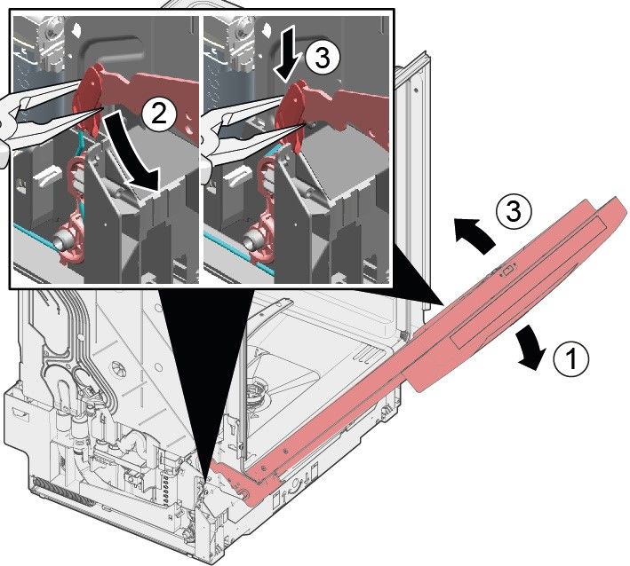
Safety
Safety

2.1 General Safety instructions
2.1.1 All domestic appliances
Risk of electric shock due to live parts!
¡ Errors by repairs involving electrical components can lead to electrical shock!
¡ Disconnect the appliance from the mains for at least 60 seconds before starting
    work.
¡ After the repair have a safety test according VDE 0701 or country-specific regula-
    tions performed.
Risk of injury from sharp edges!
¡ Wear protective gloves.
Risk of crushing during repair, maintenance, troubleshooting and service due to
heavy and moving components
¡ Wear protective shoes.
¡ Secure heavy components from falling down.
¡ Do not stick body parts into moving components.
Risk to the appliance's safety / function!
¡ Only use original spare parts.
Risk of damage to electrostatically sensitive components (ESDs)!
¡ Do not touch the modules, including connections and conductor paths.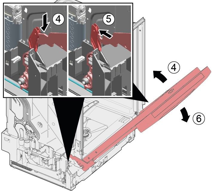
Tools and aids
Tools and aids

                 Designation            Details                        Images
                 Screwdriver Torx       100 mm, for screws with safety
                 T20 with bore hole     pin
                 [00340764]
                 Insulated Screw-       Blade length 125 mm, for
                 driver Torx T15 with   screws with safety pin
                 bore hole
                 [15000626]
                 Slotted screwdriverBlade 10 mm x 1.6 mm x
                                    200 mm
                 Needle nose pliers Length: 200 mm, straight
                 [00340871]
Repair
Repair

4.1 Replacing worktop                                                4.1.2 Installing worktop
Prerequisite:                                                        1. Lock the rear of the worktop into the guides using the retaining collars (1).
    Appliance is disconnected from the power supply.
    Appliance is freely accessible.

4.1.1 Removing worktop
         1. Remove the two screws at the back (1) (optional).
         2. Press both catch levers under the worktop upwards (2).

                                                                     2. Push worktop forwards (2).
                                                                     3. Press the front of the worktop downwards until both catch levers click audibly into
                                                                        place (3).
                                                                     4. Screw in the two screws again (4) (optional).

         3. Lift the worktop slightly at the front (3).
         4. Push worktop away towards the rear (4).
         5. Remove worktop.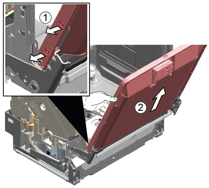
Repair

4.2 Installing basket system                                                                2. Click the cup support clip into place.

Prerequisite:
    The relevant basket has been removed from the appliance.

4.2.1 Installing a tab slide for the 86 cm model
Required tools:
    Tabguide                                                                 [00614935]
    Cup support clip                                                         [00618565]
1. Insert the tab slide diagonally at the front of the basket.
2. Centre and click the tab chute into place.

4.2.2 Installing cup support clip                                                           3. Fold up the clip.
Required tools:
    Tabguide                                                                 [00614935]
    Cup support clip                                                         [00618565]
               When washing cups, the cup support clip can be folded up. The addi-
               tional angle reduces the collection of water on the bottom of cups. In the
               case of tall glasses we recommended leaving the cup support clip folded
               down.
               If upper baskets have an optional plastic insert, they must first be re-
               moved.
1. Remove the plastic insert.
Repair 4. Position the items to be washed. ▶ Wedge the steamer insert with the end pieces under the basket system. 4.2.3 Installing steamer insert Required tools: Tabguide [00614935] Cup support clip [00618565]
Repair

4.3 Replacing varioDrawer           3. Press plastic side inserts outwards and press them upwards out of the frame.

4.3.1 Removing varioDrawer
1. Bend the handle flaps inwards.

2. Remove the handle upwards.
Repair

4. Carefully bend the guide tabs outwards.    6. Press metal frame at the front out of the holders.

5. Pull the folding spines out of the tabs.   7. Push metal frame back out of the guide.

                                              4.3.2 Installing varioDrawer
                                              ▶   Install in reverse order.
Repair
4.4 Replacing spray arms
4.4.1 Removing spray arm
1. Unscrew the upper spray arm (1) and pull down to remove (2).
1
2
2. Pull down the lower spray arm to remove.
4.4.2 Installing spray arm
1. Insert the lower spray arm.
The spray arm clicks into position.
2. Insert the upper spray arm and screw it firmly in place.Repair
4.5 Replacing filters
4.5.1 Removing filter
1. Turn the coarse filter anticlockwise (1) and remove the filter system (2).
2
1
Check that no foreign objects fall into the sump.
2. Pull down the micro filter to remove.
4.5.2 Installing filters
1. Re-assemble the filter system.
Make sure that the locking catches on the coarse filter click into position.
2. Insert the filter system into the appliance and turn the coarse filter clockwise.
Make sure that the arrow markings match up.Repair
4.6 Installing baking sheet spray head
1. Remove top basket.
2. Insert the baking sheet spray head in the holder (1) and turn to the right (2).
The baking sheet spray head clicks into position.Repair
4.7 Replacing power cord ▶ Insert the plug of the power cord into the mains socket until the plug clicks audibly
into place.
Prerequisite:
Appliance is disconnected from power supply.
Appliance is disconnected from water supply.
Appliances is freely accessible.
4.7.1 Unplugging power cord
▶ Move the plug of the power cord carefully up and down and pull it out of the mains
socket.
4.7.2 Plugging in power cord
Notice
Overheating of main connection!
Risk of fire
▶ Firmly insert the power cord until it clicks.Repair
4.8 Replacing detergent cover 4.8.2 Inserting spring
1. Insert the long end of the spring into the mounting hole of the dispenser device (1).
A small screwdriver can be used as a levering tool.
Prerequisite:
Appliance is disconnected from power supply.
Appliance is disconnected from water supply.
Door has been opened.
Detergent cover has been opened.
4.8.1 Removing detergent cover
1. Slide the detergent cover in 5 mm.
2. Lever the detergent cover on the lower side out of the guide rails and take the de-
tergent cover on the upper side out of the guide rails.
3. Remove the spring.
2. Insert the short end of the spring into the mounting hole of the detergent cover (2).
3. Press cover into the dispenser device (3).
4.8.3 Installing detergent cover
1. Insert the detergent cover 5 mm before the completely open position into the guide
rails on one side. Applying gentle force, press the opposite side into the guide
rails.
2. Check the function of the detergent cover.Repair
4.9 Replacing wastewater pump cover
Prerequisite:
Basket has been removed.
Filters has been removed.→ Page 220
4.9.1 Removing wastewater pump cover
1. Scoop out any water.
Use a sponge if necessary.
2. Prise off the pump cover using a spoon and grip it by the crosspiece.
3. Lift the pump cover inwards at an angle and remove.
4.9.2 Installing wastewater pump cover
▶ Insert the pump cover (1) and press down (2).
2
1
The pump cover clicks into position.Repair
4.10 Replacing side panel 4.10.1 Removing side panel
Prerequisite: 1. Remove screws from the side panel (1).
Appliance is disconnected from power supply.
Appliance is disconnected from water supply.
Appliances is freely accessible.
Free-standing appliances: Worktop has been removed.→ Page 214
Fig. 1: Fully integrated
2. Tilt the side panel slightly outwards at the top (2).
3. Lower the side panel and pull it out of the base trough (3).Repair
4.10.2 Installing side panel
1. Insert the side panel into the base trough (1).
Fig. 2: Fully integrated
2. Press the side panel onto the appliance (2).
3. Secure the side panel with screws (3).Repair
4.11 Replacing outer door Remove two screws.
Prerequisite:
Appliance is disconnected from power supply.
Appliance is disconnected from water supply.
4.11.1 Removing outer door
Just remove the screws which are described in the following steps.
1. Open door.
2. Remove four screws.
4.11.2 Installing outer door
Notice
Cables which are incorrectly positioned or not secured!
Damage to cabling
▶ Position the cables and secure in place with adhesive tape.
3.
Secure the door by holding it on one side.
!Repair
Prerequisite: Open the door and secure it with two screws (4 x 11 mm metal screws).
Insulating fleece has been correctly positioned and fixed on the inside of the outer
door.
Hinges are inserted into the outer door.
1. Close the inner door without snapping it shut.
2. Push the outer door upwards underneath the control panel (1).
5. Secure the outer door with four screws (4 x 11 mm metal screws).
3. Press the outer door against the inner door and hold (2).
4.
Secure the door by holding it on one side.Repair
4.12 Replacing control panel 5. Remove six screws.
If an operating module is defective, the entire control panel must be re-
placed.
Prerequisite:
Appliance is disconnected from power supply.
Appliance is disconnected from water supply.
Outer door has been removed.
Outer door has been removed (fully integrated/integrated).
4.12.1 Removing control panel
1. Disconnect electrical connections from the control panel and the low rinse-aid
sensor (1, 2).
6. Remove the control panel.
4.12.2 Installing control panel
Use screws 4 x 16 mm.
▶ Install in reverse order.
2. Disconnect the earth cable (3) (optional).
3. Open the appliance door.
4. Secure the control panel to prevent it from falling down (hold on to it).Repair
4.13 Fix door springs 2. 1. Open door slightly (1).
2. Fix in the groove of the base trough (2).
1. Remove cord guide cover out. 3. Slowly close the door (3).
The cord system attaches itself automatically to the door hinge.Repair 3. 1. Slightly close the door (4). 2. Move the groove to the back and release the door hinge (5). 3. Open the door (6). 4. Repeat the process again on other side of appliance.
Repair

4.14 Replacing toe panel                                                                   4. Remove the feet forwards (1).

              The feet are identical and can be swapped over.

Prerequisite:
    Appliance is disconnected from power supply.
    Appliance is disconnected from water supply.
    Outer door has been removed.
    Outer door has been removed (fully integrated/integrated).

4.14.1 Removing toe panel
1.                Incorrect removal.
                  If the toe panel is loosened at the side and removed, the two brack-
                  ets may break away. If only one bracket is damaged, the side can be
                  changed as the brackets are identical.
                  It is advisable to place something under the appliance at the front on
                  the side to relieve the load on the toe panel with the feet.
                                                                                           4.14.2 Installing toe panel
2. Reach into the guides (1) with a screwdriver and release the catch by pushing
   downwards.                                                                              1. Insert the feet.
                                                                                           2. Attach the toe panel at the top (1) and press it down until it audibly clicks into
                                                                                              place (2).

3. Lift the panel off.
Repair
4.15 Replacing base socket plate 3. Tilt the base socket plate carefully forwards (1).
The base socket plate is located in the lower area at the front.
Prerequisite:
Appliance is disconnected from power supply.
Appliance is disconnected from water supply.
Furniture panel (optional) has been removed.
Outer door has been removed.
Outer door has been removed (fully integrated/integrated).
Toe panel has been removed (optional).→ Page 232
4.15.1 Removing base socket plate
1. Remove two screws (1).
4.
Depending on the model series, the plug to the EmotionLight is still
secured to the base.
Unlock the plug on the catch tappet and pull to the rear (optional) (2).
4.15.2 Installing base socket plate
▶ Install the base socket plate in reverse order.
2. Disengage catch elements (2).Repair
4.16 Replacing overflow conduit 2. Release catch element at top.
The overflow conduit is located in the front lower area of the appliance.
Prerequisite:
Appliance is disconnected from power supply.
Appliance is disconnected from water supply.
Furniture panel has been removed (optional).
Outer door has been removed.
Toe panel has been removed (optional).→ Page 232
Base socket plate has been removed.→ Page 233
4.16.1 Removing overflow channel
3. 1. Insert screwdriver below metal brake (1).
Residual water 2. Gently release metal clip (2).
¡ When the drainage hose is removed, residual water may run out.
¡ Catch water or remove from the base pan with suction syringe.
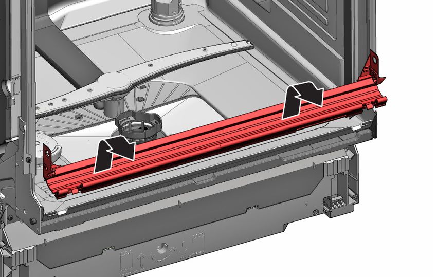
1. Lever out of the catch mechanism at the top (1, 2).Repair
4. Lift overflow conduit off. 1. 1. Place overflow conduit (1).
2. Move overflow conduit into seal (2).
3. Press overflow conduit in guide of seal (3).
4. Insert overflow conduit concisely (4).
5. Clip in overflow conduit (5).
4.16.2 Installing overflow conduit
Water damage due to incorrect installation of the overflow conduit!
Correctly insert the overflow conduit at the bottom into the guide of the
base trough.
Click the overflow conduit correctly into place at the top.Repair
2. Check installation left and right. 3. Check firm seat.
4. Clip in metal clip on left and right side.Repair
4.17 Replacing inner door 6. Secure door hinge with screws.
Prerequisite: 7. Place inner door on door hinge.
Appliance is disconnected from power supply. 8. Secure inner door with screws.
Appliance is disconnected from water supply.
4.17.1 Removing inner door
▶ 1. Remove screws (1).
2. Remove inner door upwards (2).
4.17.2 Installing inner door
1. Flap door seal to front.
2. Move inner door behind door seal.
3. Close inner door.
4. Flap door seal upwards.
Sideparts show upwards.
5. Move door hinge upwards.Repair
4.18 Replacing door hinge 2. Release ground connection on door hinge.
Prerequisite:
Appliance is disconnected from power supply.
Appliance is disconnected from water supply.
Appliances is freely accessible.
Side panel has been removed.→ Page 225
Outer door has been removed.
Inner door has been removed.
Control panel has been removed.→ Page 229
Door spings has been fixed.→ Page 230
Toe panel has been removed.→ Page 232
Base socket plate has been removed.→ Page 233
Overflow channel has been removed.→ Page 234
4.18.1 Removing door hinge
1. 1. Release catch hook with a screwdriver(1).
2. Pull door hinge forwards (2).
4.18.2 Installing door hinge
Danger
Risk of electric shock due to live parts!
Danger to life through electric shock in case of improper repair
▶ Electric parts should be repaired by a qualified electricians.
▶ After the repair have a safety test according VDE 0701 or country-
specific regulations performed.Repair
1. 1. Place hinge on appliance (1).
2. Move hinge downwards (2) till it is latched to the appliance.
2.
A missing ground connection can lead to mains potential on door.
Establish ground connection.Repair
4.19 Replacing (lower) door seal 2. Detach the overflow channel.
Prerequisite:
Appliance is disconnected from power supply.
Appliance is disconnected from water supply.
Outer door has been removed.
Base socket plate has been removed.→ Page 233
Toe panel has been removed (optional).→ Page 232
Door springs have been removed.
Control panel has been removed.
Cable harness holder on bottom right has been removed.
4.19.1 Removing the door seal
1. Remove the two retaining clips on the lower door seal (1, 2). 3. Lift the overflow gutter off.Repair
4. Remove the lower door seal from the inner door. 4.19.2 Installing the door seal
1. Fit the sealing caps on the left and right to the sealing rail with the door seal.
2. Insert the door seal with the sealing flap in the inner door.
3. Secure the door seal with two retaining clips.Repair
4.20 Replacing (upper) door seal Correctly installed door seal:
Prerequisite:
Appliance is disconnected from power supply.
Appliance is disconnected from water supply.
4.20.1 Removing door seal
▶ Remove door seal from inner frame.
4.20.2 Installing door seal
The door seal must be cut to the correct length before installation. This is 1750 mm for
appliances of 81 cm in height and 1850 mm for appliances of 86 cm in height.
1. Prepare appropriate door seal.
2. Ensure correct installation position of sealing profile.
3. White dot must be on level with sealing bed strip.
4.
Sealing must not be wavy or stretched at corners. Seal is cut off di-
agonally at ends and tapers away into bottom of container at front.
Position end of seal straight to front underneath inner door. Seal should lie against
side of container as far as possible.Repair
4.21 Replacing EmotionLight 4. Remove electrical connection from the power module.
The EmotionLight is situated in the upper front exterior area of the rinsing
tank.
Prerequisite:
Appliance is disconnected from power supply.
Appliance is disconnected from water supply.
Appliances is freely accessible.
Worktop has been removed (optional).
The right-hand side panel has been removed (optional).→ Page 225
4.21.1 Removing EmotionLight
1. Detach catch hook at the rear (1).
5. Remove EmotionLight from the appliance.
4.21.2 Installing EmotionLight
1. Insert the holder into the rinsing tank frame (1).
2. Remove the holder upwards (2).
3. Pull plug out of connector (bottom right at front of appliance).Repair
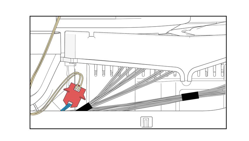
2. Engage the catch hook (2). Install the cable on the right lower side.
3.
Notice
Improper installation!
Damage to the cable in the area of the door hinge.
▶ Install the cable in the area of the door hinge (between the
plate hinge and the rinsing tank) so that it cannot be damaged
by moving parts.Repair
Fig. 3: Flat cable
4. Insert the plug.Repair
4.22 Replacing TimeLight 4.22.2 Installing TimeLight
1. Bend the catch elements (1) back again.
Replace the TimeLight only as a complete part.
The TimeLight module is fixed to the rear of the base socket plate.
Prerequisite:
Appliance is disconnected from power supply.
Appliance is disconnected from water supply.
Toe panel has been removed.→ Page 232
Base socket plate has been removed and turned.→ Page 233
4.22.1 Removing TimeLight
1. Bend the catch elements (1) slightly outwards.
2. Push the TimeLight module into the guide (2).
3. Connect the electrical connection.
2. Pull the TimeLight module upwards out of the guide (2).Repair
4.23 Replacing Gap illumination 2. 1. Detach catch hook at rear (1).
2. Remove light fibre (2).
Prerequisite:
Appliance is disconnected from power supply.
Appliance is disconnected from water supply.
Outer door is disassembled.
Operation panel has been removed.
4.23.1 Removing Gap illumination
1. 1. Detach catch (1).
2. Remove electrical connection from the operation module (2).Repair
3. 1. Detach catch hook (1). 2. Tighten it with a "click" sound.
2. Lift up PCB with holder and remove it from operation module frame (2).
3. Install light fibre and tighten it with a "click" sound.
4.23.2 Installing Gap illumination
1. Insert PCB holder to operation module frame.
4. Connect wire to operation module.LORD Hausgeräte GmbH
Greschbachstraße 17
762 29 Karlsruhe
Deutschland
www.lord.eu
info@lord.euYou can also read