HVS/HVM Combiner Box Battery-Box Premium - BYD Smart Device Hungary Kft.
←
→
Page content transcription
If your browser does not render page correctly, please read the page content below
Battery-Box Premium
HVS/HVM Combiner Box
Installation Manual
Model: CBH-40A
 V1.2

BYD Smart Device Hungary Kft.
Battery Box Premium HVS/HVM Combiner Box                                     BYD Smart Device Hungary Kft.

Legal Provisions
All the information in this document is the property of BYD Smart Device Hungary Kft. No part
of this document could be reproduced in any way for business use. Internal use is allowed.
BYD Smart Device Hungary Kft. makes no representations or warranties express or implied, with
respect to this document, including (with no limitation) any implied warranties of utility,
merchantability, or fitness for any particular purpose. All such representations or warranties are
expressly disclaimed. Neither BYD Smart Device Hungary Kft. nor its distributors or dealers shall
be liable for any indirect, incidental, or consequential damages under any circumstances.
The exclusion of implied warranties may not apply in all cases under some statutes, and thus the
above exclusion may not apply.
This document does not replace and is not intended to replace any local, state, provincial, federal, or
national laws, regulations, or codes applicable to the installation, electrical safety, and use of the
battery system. BYD Smart Device Hungary Kft. assumes no responsibility for the compliance or
noncompliance with such laws or codes in connection with the installation of the battery system.
Specifications are subject to change without notice. Every effort has been made to make this
document complete, accurate, and up-to-date. However, BYD Smart Device Hungary Kft. may
need to make some improvements under certain circumstances without advance notice. BYD
Smart Device Hungary Kft. shall not be responsible for any loss caused by this document,
including, but not limited to, omissions errors, typographical errors, arithmetical errors, or listing
errors in this document.
All trademarks are recognized.
BYD Smart Device Hungary Kft.
H-2071 Páty, Szent József út 4.

Installation Manual V1.2                                                                                 2
BYD Smart Device Hungary Kft.                                                                               Battery Box Premium HVS/HVM Combiner Box

Content
Legal Provisions................................................................................................................................................................ 2
1.     Information on this Document ............................................................................................................................ 5
        1.1.       Validity ........................................................................................................................................................... 5
        1.2.       Target Group................................................................................................................................................ 5
        1.3.       Symbols ......................................................................................................................................................... 5
2.     Safety .......................................................................................................................................................................... 6
        2.1.       Intended Use ................................................................................................................................................ 6
        2.2.       Instructions and Warnings ........................................................................................................................ 6
        2.3.       Position and securing ................................................................................................................................ 6
        2.4.       Safety Precautions ...................................................................................................................................... 6
3.     Scope of delivery ..................................................................................................................................................... 8
4.     Product Description ................................................................................................................................................ 9
        4.1.       Circuit Diagram............................................................................................................................................ 9
        4.2.       Type Label..................................................................................................................................................... 9
        4.3.       Symbols on the Type Label .................................................................................................................... 10
5.     Assembly................................................................................................................................................................... 11
        5.1.       Wall Mounting ............................................................................................................................................ 11
                5.1.1.         Selecting the Mounting Location .............................................................................................. 11
                5.1.2.         Mounting the Combiner Box ..................................................................................................... 11
6.     Electrical Connection ............................................................................................................................................ 13
        6.1.       Connection Instructions .......................................................................................................................... 13
                6.1.1.         Preliminary Checks ....................................................................................................................... 13
                6.1.2.         Safety during Electrical Connection ........................................................................................ 14
        6.2.       Inserting the Cables into the Switch Cabinet .................................................................................... 14
                6.2.1.         Bottom view of Combiner Box with cable glands ............................................................... 14
                6.2.2.         Overview of the Connection Area ........................................................................................... 15
        6.3.       Leading the Cables through the Cable Glands with sealing Gasket ........................................... 15
        6.4.       Connecting the DC Cables ..................................................................................................................... 16
        6.5.       Connecting the Grounding Cable ........................................................................................................ 17
7.     Maintenance ........................................................................................................................................................... 18
        7.1.       Periodic Maintenance .............................................................................................................................. 18
        7.2.       Extraordinary Maintenance .................................................................................................................... 18

3                                                                                                                                                    Installation Manual V1.2
Battery Box Premium HVS/HVM Combiner Box BYD Smart Device Hungary Kft.
8. Decommissioning .................................................................................................................................................. 19
8.1. Disassembling the Combiner Box ........................................................................................................ 19
8.2. Disposing of the Combiner Box ............................................................................................................ 19
9. Technical Data ....................................................................................................................................................... 20
10. Contact Information .................................................................................................................................... 22
Installation Manual V1.2 4BYD Smart Device Hungary Kft. Battery Box Premium HVS/HVM Combiner Box
1. Information on this Document
1.1. Validity
This document is valid for the Battery-Box Premium HVS/HVM Combiner Box CBH-40A.
1.2. Target Group
The instructions in this document may only be performed by qualified persons who must have the
following skills:
• Knowledge of how batteries work and are operated
• Knowledge of how an inverter works and is operated
• Knowledge of, and adherence to the locally applicable connection requirements, standards, and
directives
• Knowledge of, and adherence to this document and the associated system documentation,
including all safety instructions
• Training in dealing with the hazards associated with the installation and operation of electrical
equipment and batteries
• Training in the installation and commissioning of electrical equipment
Failure to do so will make any manufacturer's warranty, guarantee or liability null, and void unless
you can prove that the damage was not due to non-compliance.
1.3. Symbols
Symbol Explanation
Indicates a hazardous situation which, if not avoided, will result in death or
serious injury
Indicates a hazardous situation which, if not avoided, can result in death or
serious injury
Indicates a hazardous situation which, if not avoided, can result in minor or
moderate injury
Indicates a situation which, if not avoided, can result in property damage
Packaging instructions
5 Installation Manual V1.2Battery Box Premium HVS/HVM Combiner Box BYD Smart Device Hungary Kft.
2. Safety
2.1. Intended Use
2.2. Instructions and Warnings
Failure to follow these instructions may have serious consequences, such as the destruction of the
device, personal injury or death due to electric shock. Therefore, the following safety instructions
must be read and understood prior to installation and use of the Combiner Box. For any clarifications
or additional information, contact the BYD local service.
Symbol Explanation
Once the product has been removed from its original packaging, visually
inspect for damage that may have occurred during shipment. If damage is
found, contact the distributor or manufacturer.
This product must only be used for the purpose for which it has been
designed. Any other use is considered improper and therefore dangerous.
The manufacturer is not liable for possible damage caused by improper,
incorrect or unreasonable use
BYD holds itself responsible only for the product in its original
configuration. BYD declines all responsibility for consequences deriving
from non-original spare parts.
Any intervention that alters the structure or the operating cycle of the product
must be carried out or authorized by BYD Smart Device Hungary Kft.
This manual is an integral and essential part of the product. Carefully read
the recommendations contained in it since they provide important
information on safe use and maintenance.
BYD may make technical changes in this manual and to the product at any
time without notice. In case of typing errors or other types of errors, the
corrections will be included in the new versions of the manual.
2.3. Position and securing
Failure to follow these instructions may have serious consequences, such as the destruction of the
device, personal injury or death due to electric shock. Therefore, the following safety instructions
must be read and understood prior to installation and use of the Combiner Box. For any clarifications
or additional information, contact BYD local service.
Symbol Explanation
If positioning in a closed environment, make sure the area is ventilated and
allows regular recirculation of air. If installing in an open environment,
position the enclosure in an area that is constantly shaded and protected
from exposure to direct sunlight. These measures are important for
preventing unnecessary and excessive overheating, which prolonged in
time impairs the duration and operation of parts inserted inside.
Make sure the wall where the enclosure is to be mounted is suitable to
support the weight. The weight is around 10 kg.
2.4. Safety Precautions
This section contains safety precautions that must be observed at all times when working on or with
the product. To prevent personal injury and property damage and to ensure long-term operation of
the product, read this section carefully and follow all safety precautions at all times.
Installation Manual V1.2 6BYD Smart Device Hungary Kft. Battery Box Premium HVS/HVM Combiner Box
Danger to life from electric shock due to live voltage
High voltages are present in the live components of the Combiner Box. Touching live components results in
death or serious injury due to electric shock.
• Wear personal protective equipment when working on the Combiner Box.
• Do not touch live components.
• Before performing any work, always disconnect the Combiner Box from voltage sources unless supply
voltage is absolutely necessary.
• Ensure that the device cannot be reconnected.
• Ensure that no voltage is present.
• Ground and short-circuit.
• Cover or isolate any adjacent live components. Protective covers must always be mounted.
Danger to life from electric shock due to live DC cables
Touching live DC cables from batteries or an inverter results in death or serious injury.
• Prior to connecting the DC cables, ensure that the DC cables are voltage-free.
• Wear suitable personal protective equipment when working on the Combiner Box.
Danger to life from electric shock if the Combiner Box is damaged
If the Combiner Box is damaged, dangerous situations may arise during operation that results in death or
serious injury from electric shock.
• Only use the Combiner Box when it is in a technically faultless condition and safe to operate.
• Regularly check the Combiner Box for visual damage.
• Make sure that all external safety equipment is freely accessible at all times.
• Make sure that all safety equipment is in good working order.
7 Installation Manual V1.2Battery Box Premium HVS/HVM Combiner Box BYD Smart Device Hungary Kft.
3. Scope of delivery
Check the scope of delivery for completeness and any externally visible damage. Contact your
distributor if the scope of delivery is incomplete or damaged.
A B
Figure 1 Component included in the scope of delivery
A Battery-Box Premium HVS/HVM Combiner Box CBH-40A
B Installation Manual
Installation Manual V1.2BYD Smart Device Hungary Kft. Battery Box Premium HVS/HVM Combiner Box
4. Product Description
4.1. Circuit Diagram
The CBH-40A Combiner Box is a BYD battery system junction box to an inverter. Up to three HVS/
HVM battery towers could be connected in parallel with this Combiner Box.
Figure 2 Block circuit diagram of the CBH-40A Combiner Box
“1-B+”, “1-B-“ and “PE 1“ in the diagram above mean the positive power cable, negative power cable,
and grounding cable from the battery tower Number 1.
4.2. Type Label
There is one type label attached to the Combiner Box.
The type label is located on the left upside of the Combiner Box.
You will find the following information on the type label:
• Manufacturer
• Device type
• Serial number
• Device-specific characteristics
• Production date
Production date: Year Month Day
You will require the information on the type label to use the product safely and when seeking
customer support from the BYD local service. The type label must remain permanently attached to
the product.
9 Installation Manual V1.2Battery Box Premium HVS/HVM Combiner Box BYD Smart Device Hungary Kft.
4.3. Symbols on the Type Label
Symbol Explanation
Beware of electrical voltage.
WEEE designation
Do not dispose of the system together with the household waste but in
accordance with the disposal regulations for electronic waste applicable at
the installation site.
Indicates a hazardous situation which, if not avoided, will result in death or
serious injury.
Installation Manual V1.2 10BYD Smart Device Hungary Kft. Battery Box Premium HVS/HVM Combiner Box
5. Assembly
5.1. Wall Mounting
5.1.1. Selecting the Mounting Location
Fire hazard due to wrong choice of mounting location
Under fault conditions electric arcs may occur in the Combiner Box. Electric arcs can cause fires if the
Combiner Box is mounted on flammable materials.
• Do not mount the Combiner Box on flammable construction materials.
• Do not mount the Combiner Box near highly flammable materials.
• Do not mount the Combiner Box in potentially explosive atmospheres.
Requirements for the mounting location:
o The mounting location must not be in a living or office area.
o The mounting location must not block any escape routes.
o The mounting location must be freely and safely accessible at all times without the necessity for
any auxiliary equipment (such as scaffolding or lifting platforms). Non-fulfillment of these criteria may
restrict servicing.
o The mounting location must be suitable for the weight and dimensions of the Combiner Box.
o The mounting location must not be exposed to direct solar irradiation.
o The recommended height of the location is higher than 1.6 meters from the ground.
o Make sure that the Combiner Box enclosure is not mounted in the path of rainwater.
Requirements for mounting:
o Mount the Combiner Box in such a way that the connection area is facing downwards.
o The recommended height of the wall box
o Do not mount the Combiner Box in an inclined position.
5.1.2. Mounting the Combiner Box
Danger of crushing if the Combiner Box is dropped
Installation Manual V1.0
• When mounting the Combiner Box, take the weight of up to 9.7 kg into account.
• Installer should use personal protective equipment.
Installation Manual V1.2Battery Box Premium HVS/HVM Combiner Box BYD Smart Device Hungary Kft.
Damage to cable glands and plug connections due to improper transport and installation
The cable glands and plug connections protrude from the enclosure.
• When transporting and mounting the Combiner Box, ensure that the cable glands and plug connections
Additionally required mounting material (not included in the scope of delivery):
• are
Fournot
M5damaged.
screws. Take wall properties into account when choosing the screw type.
• Four washers.
• If necessary, four screw anchors. Take wall properties into account when choosing the screw
anchor type.
Figure 3 Dimensions of the Combiner Box
Procedure:
1. Mark the position of the drill holes on the wall or stand.
2. Drill holes at the marked positions.
3. If necessary, insert the screw anchors.
4. Fasten the Combiner Box to the wall or stand using suitable screws and washers.
5. Ensure that the Combiner Box is securely fixed.
Installation Manual V1.2 12BYD Smart Device Hungary Kft. Battery Box Premium HVS/HVM Combiner Box
6. Electrical Connection
6.1. Connection Instructions
6.1.1. Preliminary Checks
Before connecting the Combiner Box to the battery and inverter, make sure that:
• The Combiner Box is in good condition and there was no damage during transport.
• The Combiner Box is firmly anchored to walls and stable supports.
• There are no remaining metallic parts, chips and derivatives from the installation activities.
After performing the checks listed in the points above, proceed to wire the cables according to what is
shown in the wiring diagram, making sure to use suitable sizes and colors.
Make sure that the DC connections are properly secured inside the terminals in order to prevent possible
overheating that may lead to dangerous situations.
13 Installation Manual V1.2Battery Box Premium HVS/HVM Combiner Box BYD Smart Device Hungary Kft.
6.1.2. Safety during Electrical Connection
Danger to life due to electric shock
High voltages are present in the live components of the Combiner Box. Therefore, work on the Combiner
Box is only allowed if the power is disconnected and the guidelines that apply at the installation location are
strictly followed.
• Disconnect from voltage sources:
• Ensure that the device cannot be reconnected.
• Ensure that no voltage is present.
• Ground and short-circuit.
• Cover or isolate any adjacent live components. Protective covers must always be mounted.
6.2. Inserting the Cables into the Switch Cabinet
6.2.1. Bottom view of Combiner Box with cable glands
A
D
C
E
B
Figure 4 Bottom view of Combiner Box with cable glands
Position Description
A Cable entry for connecting positive power cables from battery towers
B Cable entry for connecting negative power cables from battery towers
C Grounding cables input from battery towers
D Output DC cable glands to an inverter
E Grounding cable output gland to a common ground point
Installation Manual V1.2 14BYD Smart Device Hungary Kft. Battery Box Premium HVS/HVM Combiner Box
6.2.2. Overview of the Connection Area
B
A
D
C
E
Figure 5 Overview of the connection area
Position Description
A Positive input cable blocks
B Negative input cable blocks
C Grounding posts for input grounding cables
D Output DC cable blocks
E Grounding post for output grounding cable
6.3. Leading the Cables through the Cable Glands with sealing Gasket
Procedure:
1. Release the cable gland.
2. Lead the cable through the swivel nut of the cable gland. Ensure that the thread of the swivel nut is
facing upwards.
3. Lead the cable through the seal insert.
4. Insert the seal insert into the cable gland together with the cable.
15 Installation Manual V1.2Battery Box Premium HVS/HVM Combiner Box BYD Smart Device Hungary Kft.
5. Cut the cable to length.
6.4. Connecting the DC Cables
BYD recommends using bootlace ferrules for connecting the DC cables to the blocks.
Damage to the Combiner Box due to moisture penetration
• Moisture can penetrate the Combiner Box through unsealed cable glands.
Cable requirements:
The diameter of the DC cables: 5 mm to 12.5 mm.
Cross section: 6 mm2 to 16 mm2
Procedure:
1. Attach the cables to an external cable support rail.
2. Cut the cables to length and strip 25 mm off the
insulation.
3. If you are using bootlace ferrules, mount the
bootlace ferrules and crimp gas-tight.
4. Lead the cables to the blocks.
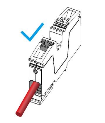
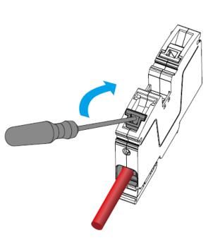
5. Insert a flat-head screwdriver into the switch of the
connector.( recommended screwdriver type, S3.5×100)
6. Hold the cables, and push up the screwdriver to make the switch go to
the end.
Installation Manual V1.2 16BYD Smart Device Hungary Kft. Battery Box Premium HVS/HVM Combiner Box 7. Make sure the switch is well fixed at the end of the sink. 8. Remove the screwdriver from the connector. 6.5. Connecting the Grounding Cable Cable requirement • Conductor cross-section: 10 -16 mm2 • Outer diameter: 5 mm to 12.5 mm • With a ring terminal Procedure: 1. Loose the original nut and washer on the ground post. 2. Put the grounding cable in the ground post. 3. Tighten the nut and washer. (torque: 5.5 Nm). 4. Ensure that the grounding cable is securely fixed. 17 Installation Manual V1.2
Battery Box Premium HVS/HVM Combiner Box                                       BYD Smart Device Hungary Kft.

7. Maintenance
7.1. Periodic Maintenance
It is recommended to periodically inspect the panel and check the following points:
• There are no evident signs of rust or corrosion which may impair functioning and safety.
(Yearly - Visual inspection)
• There are no water infiltrations and excessive dust infiltration.
(Yearly - Visual inspection)
• The mass grounding and drains are efficient.
(Yearly - Visual inspection)
• There is insulation between the electrical circuits and masses.
(5 Year - Insulation test)
• All the DC connections are correctly tightened.
(Yearly - Dynamometric torque tool)
• There are no burn marks on the terminals.
(Yearly - Visual inspection)
• The door panel of the enclosure is firmly closed at the end of all the checks and after any
maintenance.
 (Yearly - Visual inspection)

7.2. Extraordinary Maintenance
If damaged components need to be replaced only use materials identical to those originally supplied.
If the electrical connections are damaged due to mechanical or electrical causes or due to rodents,
immediately disconnect the system or at least the damaged part. After verifying that no failures were
caused to the equipment, proceed with the replacement of the wires using similar materials.

  All the maintenance operations must be performed by taking into account all safety instructions, checking
  beforehand that the components are not powered.

Installation Manual V1.2                                                                                      18
BYD Smart Device Hungary Kft.                                    Battery Box Premium HVS/HVM Combiner Box

 8. Decommissioning
 8.1. Disassembling the Combiner Box

     Danger to life due to electric shock when touching live components of the Combiner Box

     • Observe the following safety rules when disconnecting:
     – Disconnect from voltage sources.
     – Ensure that the device cannot be reconnected.
     – Check that no voltage or current is present.
     – Ground and short-circuit.
     – Cover or isolate any adjacent live components.

     Risk of burns from touching hot components

     • Wear personal safety equipment when working on the device.

 Requirement:
 The Combiner Box must be disconnected from voltage sources.
 Procedure:
 1. Open the doors of the Combiner Box.
 2. Disconnect the input cables from the blocks.
 3. Disconnect the output cables.
 4. Disconnect the grounding cables.
 5. Release the cable glands.
 6. Pull all cables out of cable glands and isolate them.
 7. Disassemble the Combiner Box.

 8.2. Disposing of the Combiner Box
 Dispose of the Combiner Box in accordance with the applicable disposal regulations for electronic
 waste.

19                                                                                       Installation Manual V1.2
Battery Box Premium HVS/HVM Combiner Box BYD Smart Device Hungary Kft. 9. Technical Data General Data Maximum Operating Voltage (Un) 1000V DC Rated Insulation Voltage (Ui) 1000V DC Rated Impulse Voltage (Uimp) 6kV Maximum input current per battery tower 35 A Maximum output current 40A Rated Current of the ASSEMBLY (InA): 40A Rated short-time withstand current (Icw) <10kA Pollution degree 3 Fuse holder Rail Mounting -1,500 VDC Fuse type 40A 22x58 - 1,500 VDC - gPV MECHANICAL DATA Enclosure SGCC (Galvanized Cold Rolled Steel) Length/ Width/ Height 540×350×120mm Weight 9.7kg Degree of Protection IP55 Type of electrical connection FFF – fixed connection Form of separation Form1 (no internal separation) Installation Manual V1.2 20
BYD Smart Device Hungary Kft.                                      Battery Box Premium HVS/HVM Combiner Box

     ENVIRONMENT DATA

     Ambient temperature during normal operation         -10~+50℃ (Note 1)

     Ambient temperature during storage                  -10~+50℃

     Humidity                                            0 % to 95 % non-condensing

     Altitude                                            up to 4,000 m (Note 2)

     DC INPUT DATA

     Maximum number of battery towers                    3

     Input cable glands entry                            9 M20×1.5 with 1 input each

     Input connection                                    Directly on terminal blocks

     DC conductor cross-section                          6 mm2 to 16 mm2

     Ground cable cross-section                           10 mm2 to 16 mm2

     DC OUTPUT DATA

     Output cable glands entry                            3 M20×1.5 with 1 input each

     Input connection                                     Directly on terminal blocks

     DC conductor cross-section                           6 mm2 to 16 mm2

     Ground cable cross-section                           10 mm2 to 16 mm2

 (Note 1): Derating of 0.5%/K of max. current from 40°C to 50°C.

 (Note 2): Derating of maximum voltage versus altitude. 1.5 % per 100 m from 2,001 m to 3,000 m.

 1.0% per 100 m from 3,001 m to 4,000m.

21                                                                                      Installation Manual V1.2
Battery Box Premium HVS/HVM Combiner Box BYD Smart Device Hungary Kft.
10. Contact Information
BYD Global Service
bboxservice@byd.com Social media link
Telephone: +86 755 89888888-47175 https://www.facebook.com/BatteryBoxBYD/
Address:No.3009,BYD Road, https://twitter.com/BYD_BatteryBox
Pingshan,Shenzhen,518118,P.R.China
https://www.linkedin.com/company/byd-battery-box
www.bydbatterybox.com
Australia Alps Power Pty Ltd Europe EFT-Systems GmbH
service @alpspower.com.au service@eft-systems.de
Telephone: +61 2 8005 6688 Address: Telephone +49 9352 8523999
14/47-51 Lorraine St Peakhurst NSW
221 +44 (0) 2037695998(UK)
www.alpspower.com.au +34 91 060 22 67(ES)
+39 02 873683(IT)
Address: Bruchtannenstraße 28, 63801
Kleinostheim, Germany
www.eft-systems.de
South AFRIPLUS ENERGY GROUP (PTY) LTD USA BYD US service
Africa
Support@afriplusenergy.co.za bboxusservice@byd.com
Telephone: +27 21 140 3594 Telephone: +1(833) 338-8721
Address: The Pavilion, Corner of Dock
& Portswood Road, V&A
WATERFRONT, 8001, CAPE TOWN
Installation Manual V1.2 22You can also read