Hydropower Providing Flexibility for a Renewable Energy System - Three European Energy Scenarios
←
→
Page content transcription
If your browser does not render page correctly, please read the page content below
Hydropower Providing Flexibility for a
Renewable Energy System
Three European Energy Scenarios

        This project has received funding from the European Union’s
        Horizon 2020 research and innovation programme under grant
        agreement No 764011.
THREE EUROPEAN ENERGY SCENARIOS

Authors
Marius Siemonsmeier*, RWTH Aachen University (Germany)
Philipp Baumanns, RWTH Aachen University (Germany)
Niklas van Bracht, RWTH Aachen University (Germany)
Maik Schönefeld, RWTH Aachen University (Germany)
Andrea Schönbauer, RWTH Aachen University (Germany)
Albert Moser, RWTH Aachen University (Germany)
Ole Gunnar Dahlhaug, NTNU Norwegian University of Science and Technology (Norway)
Sara Heidenreich, NTNU Norwegian University of Science and Technology (Norway)

*Corresponding author: si@iaew.rwth-aachen.de

                                       December 2018

This report is a revised version of the HydroFlex Deliverable 2.1.:
Baumanns, P., Siemonsmeier, M., van Bracht, N., Schönefeld, M., Schönbauer, A., Moser, A.,
Dahlhaug, O. & Heidenreich, S. (2018): Deliverable D2.1 Report defining three European energy
scenarios. Trondheim: HydroFlex.

This report reflects only the authors’ views and the Innovation and Networks Executive
Agency (INEA) is not responsible for any use that may be made of the information it contains.

Suggested citation: Siemonsmeier, M., Baumanns, P., van Bracht, N., Schönefeld, M.,
Schönbauer, A., Moser, A., Dahlhaug, O. & Heidenreich, S. (2018): Hydropower Providing
Flexibility for a Renewable Energy System: Three European Energy Scenarios. A HydroFlex report.
Trondheim: HydroFlex.

                                              1
THREE EUROPEAN ENERGY SCENARIOS
Executive Summary
The Horizon 2020 Project ‘Increasing the value of Hydropower through increased Flexibility
(HydroFlex)’ aims towards scientific and technological breakthroughs to enable hydropower
to operate with very high flexibility in order to utilise the full power and storage capability.
The project will create the environmental, social and technical basis for successful future
industrial developments by performing well-focused research and innovation activities on
the key bottlenecks of hydropower units that restrict their operating range and thus limit
their flexibility.
One objective of the HydroFlex project is to develop a water turbine capable of doing a
significant number of starts and stops per day. Work package 2 aims to investigate if there
is a demand for such a turbine in the future power system, for example from an economical
perspective in the power markets or from a technical perspective in terms of grid operation
and short term system stability. To fulfil this task, simulations of the future European power
system are needed. As the future development of the European power system is subject to
uncertainty, this report defines three European energy scenarios as a framework to cover
various future developments in the simulations.
At first, this report explains the status quo of electricity generation in Europe as well as
fundamental knowledge related to the term flexibility. Flexibility provision needs to meet
certain demands caused by different elements of power systems. This report also presents
different flexibility options able to cover these demands for flexibility. Although all provide
individual advantages, this report identifies hydropower, especially pumped storage
hydropower, to be a very flexible, diverse option and a technology capable of facing flexibility
challenges set by the increase of intermittent renewable energy sources.
Hydropower is especially common in the Nordic and Alpine countries and might provide
flexibility. Assessments of future possibilities regarding this technology should therefore
consider hydropower located in these countries. In order to evaluate requirements for
hydropower providing flexibility, factors are described, which are essential to the future
success of this possibility. As the future is subject to uncertainty, numerous outlines of the
future European power system are available, designed by different parties involved in power
systems. This report examines existing scenarios on possible opportunities of hydropower
based on the mentioned factors.
Finally, this report defines three scenarios, the Green Hydro, Reference and Prosumer
scenario, which are specifically designed as suitable input for the following computational
simulations of the European power systems. To evaluate the possible profitability of
hydropower and to achieve HydroFlex’s main objective, the scenarios describe different
contexts for Nordic hydropower.
2THREE EUROPEAN ENERGY SCENARIOS
Table of Contents
Executive Summary ............................................................................................. 2
Table of Contents ................................................................................................. 3
Abbreviations........................................................................................................ 5
1. Introduction .................................................................................................. 7
1.1 Background and motivation .................................................................................... 7
1.2 Aims and structure of the report............................................................................. 8
2 Evaluation of flexibility in the light of future European power systems ... 9
2.1 The status quo of European power systems .......................................................... 9
2.2 Flexibility within European power systems .......................................................... 13
2.2.1 Demands on flexibility provision ....................................................................... 13
2.2.2 Four kinds of flexibility ...................................................................................... 19
2.2.3 Essential factors for flexibility .......................................................................... 31
3 IAEW toolchain – power system simulation ............................................ 33
3.1 Market.................................................................................................................... 33
3.2 Grid operation ........................................................................................................ 34
3.3 Stability.................................................................................................................. 34
4 Scenario development with regard to subsequent simulations .............. 36
5 ENTSO-E’s scenarios of future European power systems ....................... 38
5.1 Storylines ............................................................................................................... 38
5.1.1 Sustainable Transition ...................................................................................... 38
5.1.2 Global Climate Action ........................................................................................ 39
5.1.3 Distributed Generation ...................................................................................... 39
5.2 Meta-analysis of ENTSO-E’s scenarios with respect to flexibility and
hydropower ............................................................................................................................ 40
5.2.1 IRES shares........................................................................................................ 40
5.2.2 Distribution ratio ................................................................................................ 42
5.2.3 Base load power plants ..................................................................................... 43
5.2.4 Peak load power plants ..................................................................................... 47
5.2.5 Proportion of hydropower plants to other flexibility options ........................... 48
5.2.6 Grid expansion ................................................................................................... 49
3THREE EUROPEAN ENERGY SCENARIOS
5.2.7 Net Transfer Capacities..................................................................................... 49
6 Deriving scenarios of European power systems placing high demands on
hydraulic power plants ............................................................................... 50
6.1 Three scenarios of European power systems ...................................................... 52
6.1.1 Reference Scenario ........................................................................................... 53
6.1.2 Green Hydro Scenario........................................................................................ 56
6.1.3 Prosumer Scenario ............................................................................................ 59
6.2 Scenarios on frequency stability .......................................................................... 63
7 Conclusion and future prospect ................................................................ 65
Bibliography ........................................................................................................ 67
Table of figures................................................................................................... 77
Table of tables .................................................................................................... 79
4THREE EUROPEAN ENERGY SCENARIOS
Abbreviations
CAES Compressed-air energy storage systems
DG Distributed Generation
DSM Demand Side Management
ENTSO-E European Network of Transmission System Operators for Electricity
EU European Union
GCA Global Climate Action
IAEW Institut für Elektrische Anlagen und Energiewirtschaft
Institute of Power Systems and Power Economics
RWTH Aachen University
IRES Intermittent Renewable Energy Sources
MAF Mid-term Adequacy Forecast
NTC Net Transfer Capacity
PRIMES Price-Induced Market Equilibrium System
PSH Pumped Storage Hydropower
RES Renewable Energy Sources
ST Sustainable Transition
TSO Transmission System Operators
TYNDP Ten-Year Network Development Plan
5THREE EUROPEAN ENERGY SCENARIOS
1. Introduction
1.1 Background and motivation
The Paris Agreement [1], signed in 2015, unites the entirety of the world’s nations on a single
goal: proceed against global climate change. The fact that nearly 200 countries are
collaborating on one issue stresses the importance of limiting global warming and lowering
carbon emissions. The success of this global collaboration will be mainly determined by
changes in the usage of fossil fuels within the energy sector in particular. Their use in
electricity generation is a significant contributor to greenhouse gas emissions. [2–5]
In the wake of the Paris Agreement, nearly all countries involved are changing their climate
policies. Among these, the European Union (EU) has a history of pushing for climate action
where it assumes a leading role in climate policy on the European continent. In order to emit
fewer greenhouse gases, European countries have combined their efforts and agreed on
common climate policies. They are planning to reduce the amount of climate-damaging
fossil-fuelled power plants, e.g. hard coal and lignite. To cover electricity demand, European
countries are increasing the share of renewable energies within their power systems. [2; 3]
Renewable energy sources (RES) are – in contrast to fossil fuels – considered
climate-friendly. The term RES refers to, among others, wind and solar energy, biomass as
well as hydropower. These energy resources are able to restore themselves, but are
flow-limited [6]. They have the ability to generate electricity without utilizing fossil fuels. [6;
7]
In order to implement the Paris Agreement and reach climate goals, European countries have
been increasing the amount of RES, in particular, wind and solar power units. As electrical
power generation (actual electrical power output) by wind and solar power plants fluctuates,
these technologies will be referred to as intermittent renewable energy sources (IRES) in this
report. The fluctuating electrical power generation by IRES causes several challenges, which
European countries have to find solutions for. Supply-dependent IRES increase the need for
technologies able to balance power systems by providing flexibility.
In a joint effort of 16 research and industry partners from five European countries, the
HydroFlex project ‘Increasing the value of Hydropower through increased Flexibility’ explores
the role of hydropower as a flexibility option. HydroFlex is a research and innovation action
funded under the EU Horizon 2020 programme “H2020-EU3.3.2 – Low-cost, low-carbon
energy supply”. It addresses the technology-specific challenge “Hydropower: Increasing
flexibility of hydropower” of the work programme topic “LCE-07-2016-2017 – Developing the
next generation technologies of renewable electricity and heating/cooling”, which focuses
on the need to develop new technologies, generators and turbine designs to increase the
flexibility of hydropower plants while mitigating environmental impacts. The project is
divided into seven work packages. Figure 1 depicts the tasks of work package two (WP2),
which this report originates from.
7THREE EUROPEAN ENERGY SCENARIOS
T 2.1 Energy Scenarios T 2.2 Reference Sites T 2.3 Simulations T 2.4 Guide
Figure 1: Tasks of work package 2
The main objective of WP2 is to identify and describe the demands hydropower plants will
be confronted with in future power systems. The focus will be on identifying dynamic loads
such as those resulting from providing high ramping rates and frequent start-stop-cycles. In
order to achieve this main objective, future flexibility demands need to be taken into account
in this project. As the future is subject to uncertainty, computational simulations based on
various scenarios provide suitable assessments of the future. Therefore, this report defines
three energy scenarios to fulfil task 2.1. In the further course of this work package, the
identification of reference sites, the simulations and a guide describing the operational
requirements hydropower plants have to meet in the future will follow. [8–10]
1.2 Aims and structure of the report
The aim of this report is to derive three scenarios suitable to model the range of future
developments in computational simulations as well as to examine demand on future
flexibility and profitability of hydropower. These scenarios will serve as suitable input for the
simulations created subsequent to this report. These will judge the suitability of hydropower
as a flexibility option.
In order to provide a framework for judging hydropower’s options in the future, chapter 2
explains the status quo of electricity generation in Europe as well as fundamental knowledge
related to the term flexibility. Flexibility provision needs to meet certain demands caused by
different elements of power systems. This chapter also presents different flexibility options
able to cover these demands. It aims to identify the currently most suitable flexibility option.
Based on these findings, section 2.2.3 presents factors essential to appropriately judge
future possibilities for Nordic hydropower. Chapter 3 describes the tool chain processing the
simulations and chapter 4 provides an overview about scenario development with regard to
the subsequent simulations.
As the future is hard to estimate, numerous outlines of future power systems are available,
designed by different parties involved in power systems. Chapter 5 examines existing
scenarios on possible opportunities of hydropower.
Chapter 6 explains three scenarios based on the findings of the previous chapter. These
scenarios are specifically designed as suitable input for computational simulations of the
European power systems. To evaluate the flexibility provision by hydropower plants, these
explanations describe different contexts for Nordic hydropower represented by the Green
Hydro, Prosumer and Reference scenarios.
8THREE EUROPEAN ENERGY SCENARIOS
2 Evaluation of flexibility in the light of future European
power systems
The following chapter first explains the status quo of European power systems. Secondly, it
describes demands on flexibility provision as well as options able to provide flexibility. The
chapter ends with the conclusion of factors essential to an evaluation of flexibility provision
in future European power systems.
2.1 The status quo of European power systems
Due to the characteristics of Europe comprising of several nations, the European power
systems can also be seen as a union made up by the electricity supply of each country. They
have developed individually within each country. The design of power systems in the late
19th and early 20th century was not meant to transmit electricity long-distance. Mostly
centralised systems with large fossil-fuelled power plants developed in close proximity to
demand centres. These areas of supply expanded as technology was evolving, but remained
limited. Consequently, countries were not necessarily well-connected to the power system
of their neighbouring country. These large-scale, mostly fossil-fuelled power plants have
shaped European power systems.
The same accounts for nuclear power plants. Their shares in electrical energy production
(amount of electrical energy generated) increased in the 1950s. Figure 2 depicts the shares
in electrical energy production, within Europe as of 2016, of the following four types of
generation: hydropower, nuclear, fossil fuels, and RES excluding hydropower. As can be seen,
nuclear and fossil fuels combined still amount to over 60%. Therefore, they still play an
important role in electricity supply today. [11–13]
RES
excluding
Hydropower
hydropower
17%
17%
Fossil fuels Nuclear energy
41% 25%
Figure 2: ENTSO-E shares of electrical energy production in 2016 [14]
9THREE EUROPEAN ENERGY SCENARIOS
Reflecting European countries’ diversity, their composition of power plant units vary
profoundly. They have grown nationally due to different geographical aspects, regional
availability of primary energy sources and political objectives. At the beginning of electricity
generation, countries used resources found within their territories. They developed the
infrastructural means to transport these resources over short distances to large electrical
power generation units. E.g., Germany has built its power supply on coal and lignite deposits
mined in its western and eastern regions. These resources have also been mined within
neighbouring countries of Germany or have been imported from Germany.
Figure 3 illustrates the share of fossil fuels electrical energy production within Europe in
2016 on the left hand side. As can be seen, Germany and adjacent countries still rely on fossil
fuels to a great extent, mostly due to this historical development. [11; 15–17; 13; 18–20] In
contrast, Nordic countries traditionally used the advantage of their topography to generate
hydropower. Figure 3 also depicts this particular Nordic characteristic by showing the share
of hydraulic electrical energy production within Europe on the right hand side. Sweden
includes hydropower to approximately 40%. Norway’s share in hydropower even amounts to
over 95% of its electrical energy production.
France on the other hand has always been relatively low in fossil resources. To become more
independent from importing fossil fuels, France turned to nuclear energy as an alternative in
the 1970s. Today, France derives approximately 80% of its electrical energy production from
the nuclear sector. These examples illustrate the following: Europe consists of many
countries, all of which have their own characteristics. Their power systems and preferred
source of energy reflect this diversity. [15–17; 13; 18; 20; 14]
0 74
96
21
24
2 2 41
86 0,3
46 40
38 0,1
30 28
75 3
56 85 85 2 0,1
56 2
2 5
29
13 58 74 4
18 19
20 36 55 0,9
9 2 60
29 39 12 31 30
65 73 3 27
32 54
59 41 45 4 11
16 59
42 73 66 27 31
30
38 64 15 13
95 0,0
Lowest Highest
Figure 3: Share of fossil fuels (left) and hydropower (right) in total national electrical energy
production [14]
Although having mostly individual power systems, European countries established
cross-border transmission capacities where it was reasonable regionally. Switzerland for
example, due to its geography and high amount of hydropower generation, linked parts of its
10THREE EUROPEAN ENERGY SCENARIOS
system to bordering parts of Germany, Italy, and France as early as the late 19th century [13].
Individual connections like these were rare at first and there was no methodical
interconnecting of several countries. Over time, European countries established more and
more of these links, connecting a growing number of countries in Continental Europe. [13;
21; 22]
These links were possible as all these different power systems are based on the same
underlying technical standards. European countries implemented for the better part 50 Hertz
as their standard system frequency as early as the beginning of the 20th century. Nowadays
power systems either function with 50 or 60 Hertz worldwide; the latter being used on the
American continent while the former on most of the others. The frequency is a measure of
balance between the amount of energy generated and demanded. It is an important and
necessary tool as electrical grids are not able to store electricity. This balance is shown in
Figure 4: when demand is higher than generation, the frequency drops and vice versa. These
imbalances happen naturally as neither demand nor generation are completely certain. As
the basic principle of energy conservation dictates, the amount of energy within the system
has to be balanced at any time. Therefore, flexibility options, such as hydropower plants, are
essential to the power system. [23; 21; 24; 13; 22]
Demand Generation
Figure 4: The balance of load and generation [25]
During the last century, European countries have continued to agree on common standards
and to interconnect their power systems. Especially after World War II, they have increased
collaboration on many issues, including electricity. [26; 22] They have formed several
foundations and have initiated international standardisation regarding power systems, their
history described in detail by [26] and [22]. These ambitions resulted in today’s European
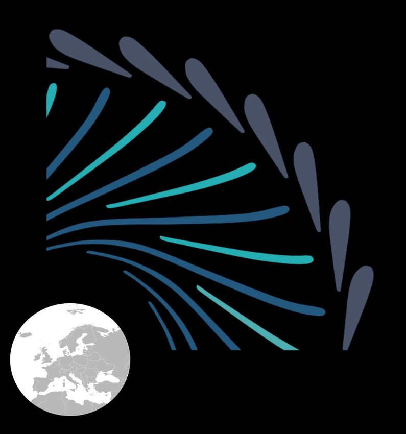
Network of Transmission System Operators for Electricity (ENTSO-E), a pan-European
organisation currently including 43 Transmission System Operators (TSOs) from 36 EU and
non-EU countries [27]. Figure 5 illustrates these member countries. As shown, the ENTSO-E
area covers the majority of Europe. The member countries are organised regionally as
synchronous areas, also illustrated in Figure 5. As outlined in [28], ENTSO-E was founded to
improve coordination between TSOs. This includes, but is not limited to, the development of
a European transmission system as well as the development and monitoring of the
implementation of network codes. To ensure implementation, ENTSO-E takes actively part
in the development of European regulations, especially in close cooperation with
EU legislation. [28]
11THREE EUROPEAN ENERGY SCENARIOS
Nordic
Continental Europe
United Kingdom and Ireland
Baltic
Observer Member
Figure 5: The origin of member TSOs of ENTSO-E [27]
European countries have also most notably agreed on decreasing their environmental
emissions and limiting global warming. As one result of these agreements, they have
introduced policies to increase the amount of emission-free RES considerably within their
systems and strategies on how to include them. These plans also include altering their
composition of power plant units. Clearly, European countries will need to build more RES
and implement them into power systems. These countries will achieve less emissions most
effectively by decreasing the usage of fossil-fuelled power plants. These changes will affect
not only the composition of power plant units, but also the structure of transmission grids,
as will be explained in the course of this chapter.
12THREE EUROPEAN ENERGY SCENARIOS
Figure 6 shows the course of electrical energy production by fuel within the EU. Starting in
1990, it illustrates the decline of fossil fuels and the rise of RES until the year 2015.
Traditionally most used fossil fuels are decreasing while renewables are steadily increasing.
A change within European power systems towards RES has begun. Continuing on this path
towards one pan-European power system primarily supplied by RES, European countries
have to face several challenges. [12; 29–31]
700
Mtoe
500
400
300
200
100
0
2012
1990
2014
1996
1992
1994
1998
2000
2002
2004
2006
2008
2010
Nuclear Fossil fuels RES Wastes, Non-RES
Figure 6: Electrical energy production by fuel in the EU (1990-2015) [32]
2.2 Flexibility within European power systems
As the electrical power generation in renewable European power systems will fluctuate
depending, inter alia, on the weather, the need for balancing will increase. Flexibility options,
such as hydropower plants, could become more important. The more measures available
within a system to balance demand and generation, which derivate in time, the more
flexibility it offers [33]. The term flexibility in a broad sense describes the mere potential to
balance the generation and demand by adjusting the electrical power generation or demand,
whenever there is a deviation from the usual amount in the system. These imbalances
originate from different elements of the power system and put different demands on the
source of flexibility. [33–35; 30; 36; 37; 9]
2.2.1 Demands on flexibility provision
The following will explain fundamental causes of flexibility demands such as power plant
outages, load fluctuation, and fluctuation in power generated by RES. In principle, it is the
task of the wholesale electricity markets to match demand and supply. Nevertheless, short-
term imbalances occur due to the limited temporal resolution of products or uncertain
circumstances. Regulatory control regularises today’s control actions to balance those
imbalances. Finally, this section deals with grid congestion management, which requires
flexibility as well.
13THREE EUROPEAN ENERGY SCENARIOS
2.2.1.1 Power plant outages
When designing power systems, fossil-fuelled power or hydropower plants primarily ensured
electrical power generation. The output of these power plants is dispatchable. Nevertheless,
the availability of power plants is limited because of unforeseeable failures of power plants.
These losses happen continuously, stochastically and need to be compensated by other
means. Disturbances do not have to be within gigawatts to disturb the power system: Even
minor outages of power plants can cause a derivation from the standard frequency. [8, 38]
2.2.1.2 Load fluctuation
Another fundamental cause for an imbalance of demand and generation is load fluctuations.
The demand side has always been volatile as it consists of numerous differing components.
Large industrial complexes with relatively steady and high electricity demand can cause a
high discrepancy if disconnected suddenly. Multitudes of small consumers who can connect
and disconnect household appliances or small devices at any time are uncertain in their
individual behaviour and account for a natural fluctuation in demand. Therefore, load is not
homogeneous, but varies in time and amount. [38; 8]
Using data and experience of load development, demand can be categorised into base,
medium, and peak load. Figure 7 shows these three categories in a generic load curve
example over an exemplary 24-hour period. Base load refers to the amount of consumption
which is almost the minimum over a span of time; therefore representing the base of the
area shown in Figure 7. Its level can differ in between seasons or within a day. For example,
the electricity use is higher during operational hours of businesses than at night. It is also
higher in winter than in summer due to electrical space heating. These differences are well
known using historical data. If demand levels exceed this base level within smaller spans,
the term medium load is used, highlighted in Figure 7. If demand levels change within higher
spans and shorter time frames, they exceed the medium load and the term peak load applies.
As can be seen in Figure 7, peak load occurs during a smaller period of time and to a lower
extent. [7; 39–41; 8]
Peak load
Medium load
Base load
1 3 5 7 9 11 13 15 17 19 h 23
Figure 7: A generic load curve example [42]
With regard to the short-term load fluctuation, it is necessary to distinguish between
forecasting errors and noise. Figure 8 exemplarily illustrates short-term fluctuations in load
over time and their deviation from forecasted values. Prognoses refer to time intervals as
14THREE EUROPEAN ENERGY SCENARIOS
small as possibly tradeable on electricity markets, mostly 15 minutes. An exemplary
prognosis is highlighted in blue. Within one interval of 15 minutes, the forecasting error is
the difference between the average value of actual load, inscribed in red, and the value of
prognosis. As the demand of electricity is fluctuating, short-term variations occur. The
deviation of load from its average value is called noise. Both deviations cause the need for
flexibility options, such as hydropower plants. [43]
Noise
Power
Forecasting
error
00:00 00:15 hh:mm 00:45
time
Actual load Actual value of prognosis Average value
Figure 8: Short-term fluctuations and forecast errors in load
The power systems have grown to meet these demands as they occur and have adapted to
these fluctuations. As electrical power generation is becoming increasingly renewable, the
residual load gains greater significance. This term describes the actual electricity demand
minus the power generated by renewable energy. It has been introduced as the energy
provided by IRES must be prioritised in the power systems of most European countries.
Giving priority to the feed-in of wind and solar power is a part of their plans to include RES
into their power systems. The more energy IRES feed into the systems, the lower the amount
of residual energy and the less fossil-fuelled power plants get to supply electricity. Since
these power plants have provided a large part of the flexibility so far, other flexibility options,
such as hydropower plants, might become more important. [7; 39–41]
2.2.1.3 IRES fluctuation
The amount of energy being provided by IRES can vary within and between seasons,
depending on their type. Wind and solar energy, for example, depend on supply of wind and
solar irradiation. Figure 9 compares two days of wind and solar power feed-in in Germany.
The 22nd of September in 2017 was comparatively low in electrical power generation by IRES.
Except for midday, electrical power generation on this day was insignificant in comparison
to 26thof December the same year. Figure 9 illustrates that 26thof December accounted for
almost three times as much electrical power generation. Forecasts can, to some extent,
calculate these differences in supply beforehand, using meteorological data. As the weather
15THREE EUROPEAN ENERGY SCENARIOS
cannot yet be determined completely, different frameworks and models are available to
make such prognosis. Depending on the choice of methodology, meteorological parameters
and their variation are calculated differently. This leads to different qualities in forecasting.
The position of the sun determines solar electrical power generation output. Even though the
position of the sun is well calculable, solar radiation can be hindered by fog or clouds. The
formation of these meteorological processes is hard to simulate in a computer model, as
further explained in [44]. Errors are thus still common in forecasting. [44; 45; 8]
60
GW
40
Generated amount of power
30
20
10
0
1 2 3 4 5 6 7 8 9 10 11 12 13 14 15 16 17 18 19 20 21 22 h 24
26.12.2017 22.09.2017 Time
Figure 9: Exemplary feed-in by wind and solar power in Germany (2017) [46]
The quality of a prognosis always depends on various factors: the forecast horizon, the size
of the area considered, and the properties of facilities available within said area. This quality
can only be assessed retrospectively and consists of the prognosticated amount of energy
and the amount actually occurred. Forecast errors can be either negative or positive. If there
is more electricity being generated than forecasted, the error is negative and flexibility
options need to absorb this extra amount of energy. If there is less than expected, other
electrical power generation units have to cover the remaining demand. [44; 45; 8]
Figure 8 in paragraph 2.2.1.2 exemplarily illustrates short-term fluctuations in load over time
and their deviation from forecasted values. The distinction between forecasting errors and
noise is also valid for the electrical power generation by IRES. Prognoses refer to time
intervals as small as possibly tradeable on electricity markets, mostly 15 minutes. Within
one interval of 15 minutes, the forecasting error is the difference between the average value
of actual electrical power generation by IRES and the single value of prognosis. As the
generation by IRES is fluctuating, short-term variations occur. The deviation of actual
generation from its average value is called noise. This deviation occurs for example due to
the effects of cloud course on solar irradiation. Both deviations cause the need for flexibility
options. [43]
16THREE EUROPEAN ENERGY SCENARIOS
The forecast horizon has a significant effect on quality. Figure 10 shows the example of wind
power forecasts in Spain, from 2008 to 2012, and their forecasting errors in relation to the
forecast horizon. The shorter the forecast horizon, the smaller the forecasting error. The
limited reliability of weather forecasts hinders accurate planning of load supply. As can also
be seen in Figure 10, forecasting improved within only a few years. As the amount of IRES is
increasing and forecasting methods are still evolving, flexibility absorbing these forecasting
errors gains growing importance. [44; 45; 8]
25
%
Mean absolute error/average production
15
10
5
0
1 3 5 7 9 11 13 15 17 19 21 23 25 27 29 31 33 35 37 39 41 43 h 47
Forecast horizon
2008 2009 2010 2011 2012
Figure 10: Errors in wind power forecasts in Spain plotted against the forecast horizon [8]
2.2.1.4 Steps in unit commitment
Program changes of cross-border exchange transfer due to electricity trading activities and
thus changes in the feed-in of power plants cannot be realised immediately for technical
reasons. If such jump occurs, an inter-periodic ramping (increase or reduction) of the set
point of cross-border exchange takes place controlled by the Frequency Restoration Reserve
(described in section 2.2.1.5). This extends over a time range of up to 10 minutes. In this
time range, the feed-in power of the power plants has to be adjusted as well. As this adaption
can be non-synchronous, imbalances can occur resulting in an additional demand for
flexibility provision by e.g. hydropower plants.
2.2.1.5 Regulatory Control
Following the above-described fundamental causes of flexibility demands, control actions
have been developed in the European power system. Today, regulatory control standardises
and coordinates those measures within Europe to balance short-term imbalances.
Control actions respond within different time frames. Figure 11 shows their sequence and
interconnection. To give an example, a sudden power plant’s outage causes a derivation
from the standard frequency. This automatically activates Frequency Containment. It is a
response of all technical elements operating within the system like speed controllers of
turbines of power plants. They sense the derivation from the usual frequency within a span
of ± 20 mHz and adjust their power. This change in kinetic energy alters the amount of power
17THREE EUROPEAN ENERGY SCENARIOS
delivered until a balance between electrical power generation and consumption is re-
established. If the frequency deviates up to ± 200 mHz, every Frequency Containment
Reserve is fully activated. As Frequency Containment Reserves act as proportional control,
the frequency cannot reach its original level, but only stabilise. After 15 to 30 seconds
Frequency Restoration Reserve supersedes Frequency Containment Reserves. Frequency
Containment Reserves resources are then fully available again. Grid operators activate
Frequency Restoration Reserve automatically, which can stabilise the frequency back to its
original level. When disturbances continue after these actions, grid operators can manually
relieve Frequency Restoration Reserve and activate Replacement Reserves. Additional load
or generation can be activated within the area in which the disturbance has occurred.
Regarding a future energy system with less fossil-fuelled power plants, other options need
to be implemented to provide regulatory control. [37, 39–41]
Frequency / power
Frequency Restoration
Frequency Replacement
Containment Reserves
0
Occurrence of
the disturbance Time
Time to restore
frequency
Figure 11: Time frames and measures of regulatory control [47]
To facilitate the exchange across borders and further international standardisation, these
control actions were formulated at the beginning of the 21st century for the area of today’s
ENTSO-E [43]. ENTSO-E has also published several regulations, called network codes, which
include measures for electricity balancing and frequency restoration. Due to the high
complexity and technical differences within European power systems, the implementation
of a common European regulation and market is still in progress. These rules are widely
agreed upon, but can differ between synchronous areas, e.g. between Continental Europe
and the Nordic countries. States within these areas are also allowed to differ from
regulations when necessary or reasonable. [44, 45]
2.2.1.6 Congestion management
In order to ensure security in transmission grid operation, certain conditions must not be
violated. Power grids are built to function at the height of forecasted transmission even if
one element should fail or be shut down, therefore called (n-1)-criterion. Moreover, the level
of voltage must not change considerably and other network elements must not overload in
case of a failure. In case not all power flows can be sufficiently handled by the power grid
18THREE EUROPEAN ENERGY SCENARIOS
without violating these operating conditions, congestions occur. The TSO’s task is to prevent
these congestions, therefore called congestion management. [48; 49]
One measure to do so is called redispatch. If the operators of power grids deem it necessary,
they can order operators of power plants to reschedule their electrical power generation. As
the sum of energy being supplied cannot change in order to cover all demand, a power plant
on one end of the bottleneck needs to generate less electricity. Another plant on the other
end of the bottleneck then increases its generation. The congestion is simply avoided by this
type of rescheduling. As illustrated above, fluctuations historically occurred on the demand
side of power systems. Reliable sources on the side of generation balanced these
fluctuations. With weather dependent IRES becoming a bigger part of power systems,
congestion management has to adapt its strategies as well. [50; 48; 49]
Additionally, IRES are built at locations which promise high output, but are often remote from
demand centres. As mentioned, the power grid was designed to supply locally, not to
transmit electricity over long distances. Consequently, connecting these remote locations
as well as variability caused by both sides of power systems increase the burden put on the
power grid, the likeliness of congestions, and the complexity of managing the power flow.
With the increasing amount of IRES and delays in grid expansion projects, finding solutions
to lighten the burden on the elements of the power grid is an increasingly important task and
an opportunity for flexibility options, such as hydropower plants. [50; 19]
2.2.2 Four kinds of flexibility
Flexibility measures can be categorised into four main categories: dispatchable generation,
demand side management, increased interconnection, and energy storage [35; 51; 8]. There
are different kinds of facilities being able to provide either one or several of these types of
flexibility. [35; 51; 8; 36; 52; 42]
2.2.2.1 Dispatchable generation
Fossil-fuelled and nuclear power plants
First of all, when there is a surplus or deficit of energy within a system, one option is to alter
generation itself. Therefore, large-scale power plants are traditionally a main source of
flexibility. The sensibility of this measure depends on the properties of the facility. This type
of flexibility is hindered by four restrictions of power plants: minimum point and maximum
point of operation, ramp rate, and start-up time [53]. These key figures can vary depending
on characteristics of the facility. As fossil-fuelled power plants can be in operation for several
decades, more recently built power plants are often further developed and more dynamic.
The key figures mentioned below contain modern and older power plants. [24; 54; 36; 55]
Operating conditions of fossil-fuelled and nuclear power plants
Start-up time, as illustrated in Figure 12, is the amount of time needed for a power plant to
reach a stable point in operation, which is mostly defined as the minimum load [34]. This key
figure can generally be categorised as hot, warm, or cold start-up [56; 34]. The reason for this
distinction lies in operating conditions. The materials of power plants can only endure
certain temperature changes without damages [57]. Elements in fossil-fuelled power plants
need a certain operating temperature, which has to be regained after a standstill [57]. In the
19THREE EUROPEAN ENERGY SCENARIOS
future, power plants which are able to react quickly to fluctuations of IRES are gaining
importance. In order to balance variability of IRES, other sources of electrical power
generation will need to be able to be turned on and off quickly, within 15 to 30 minutes [8],
and often, even several times within a day. [57; 53; 58; 59; 8]
Nominal load
100
%
80
Ramp rate
70
60
Load
50
Minimum load
40
30
20
10
0 h
Time
Start-up time
Figure 12: Exemplary illustration of restrictions of fossil-fuelled power plants [53]
While in operation, fossil-fuelled power plants are often not dispatched below a certain point,
the lowest stable point of operation, as shown in Figure 12. Operating power plants at a
minimum load avoids long start-up phases and enables them to react more quickly to
changes within power systems and energy markets. In regard to the creation of power
systems, fossil-fuelled power plants are not optimised to function at low points of operation,
but to constantly cover stable amounts of base load. Concerning a future highly renewable
power system, low possible minimal loads are desirable. If electrical power generation by
IRES is considerably high, for example at peak hours of photovoltaic electrical power
generation at midday, the option of dispatching fossil-fuelled electrical power generation as
low as necessary provides valuable flexibility. [57; 59]
The third parameter for this type of flexibility, the ramp rate, is the rate at which the supply
of power can be adjusted [34; 53], again illustrated in Figure 12. It describes the potential
change in load in proportion to the nominal load of the power plant [34]. The highest rates
are achievable within the bandwidth of minimal to nominal load [34]. A high speed of load
change indicates a high flexibility. Such a power plant is able to react more quickly to
changes within power systems and power markets [57]. With IRES increasing within power
systems, higher ramp rates provide higher degrees of flexibility [59].
Base load power plants
Following the categorisation of load explained before, fossil-fuelled and nuclear power plants
are mainly used to cover base load. Due to the development of power systems, lignite and
nuclear power plants are among the earliest and most common large-scale power plants.
20THREE EUROPEAN ENERGY SCENARIOS
They used to cover mostly expectable demand curves and to be operated for long periods at
once. They are often high in investment costs, especially nuclear power plants in order to
fulfil high safety requirements [60]. Due to low variable costs, fossil-fuelled power plants are
most cost-effective over a longer period of operation [24]. Therefore, it is economically
sensible to maximise the usage of these power plants, covering the mostly constant base
load [24; 54].
After a standstill, depending on its duration, power plants can take several hours to reach a
stable point of operation again. Even if they have been standing still for less than eight hours,
lignite power plants require a run-up phase of two [61] to six hours [55; 57; 58]. The warm
and cold start-up time can take five [61] to ten hours [57]. [55; 58; 57; 61].
Given their start-up phases lignite power plants do not completely disconnect from power
systems in many cases, but operate at minimum load. These levels are about 35 to 60% of
nominal load [53; 57; 55]. This point in operation limits the flexibility of lignite power plants.
Their load change rate lies between one and four percent per minute given the fact that they
are operating at 50 to 90% of nominal load [55; 58]. Table 1, at the end of this section,
provides an overview over the characteristics of these and the following power plants.
Nuclear power plants are generally less dynamic and take longer to restore their maximum
amount of power. Despite the technical ability of these power plants to provide regulatory
power reducing their output to provide short-term regulatory actions can be less economical.
Bringing them back to a stable point of operation can last three hours for a hot, eight to
twelve hours for a warm and even up to fifty hours for a cold start-up [61; 34]. Therefore,
nuclear power plants are often in operation even if power systems do not need their output.
Them taking several days to be fully effective again would result in higher opportunity costs
as they could not supply the market. This is why they often operate at a minimal load of 50%
or higher, even though their technically possible minimum load is set at 20 to 30%. Above
this minimal load, they can provide a load change rate of 10% per minute [62]. Therefore, they
are not flexible enough to cushion short-term forecast errors of IRES. [55; 61; 34; 59]
As fossil-fuelled power plants already generate heat, there are power plants additionally
offering a combination of electricity and heat supply. The heat provided by these facilities
cannot travel long distances, but is used for heating applications and district heating
networks within a nearby area, mostly near city or industrial areas [35; 24]. As they are not
only feeding into the electricity but also the heating system, they are bound to the demands
of both systems. This additional restriction, in comparison to regular fossil-fuelled plants, is
a reason they tend to be less flexible. [24; 35; 55; 34]
As all of these base load power plants are often operated at a high amount of power, they do
not have many resources left to provide regulatory power, except Frequency Containment
Reserves. Due to their long run-up phases, they cannot react quickly to possible short-term
changes caused by IRES and cushion prognosis errors. Additionally, to reach their climate
goals, European countries will, in the long run, have to abolish fossil-fuelled sources of
electrical power generation. Their properties make base load power plants fairly inflexible
options for balancing a highly renewable power system. [54; 24; 63; 41; 64; 55; 65]
21THREE EUROPEAN ENERGY SCENARIOS
Medium load power plants
Plants for medium load are similar, but are able to regulate their power output more easily.
Plants powered by hard coal for example share many properties with lignite power plants,
but are able to regulate more easily with a slightly shorter run-up phase and higher ramp
rates. For an easier comparison of these power plants, refer to Table 1. Hard coal plants need
two to three hours to provide their full potential again after a standstill of under eight
hours [58; 57]. More recently built hard coal plants can even start up within one hour [61; 57].
Warm start-up can take three to ten, a cold one four to ten hours [61; 57]. Their minimum load
is set at 25 to 40%. During operation, they can provide tertiary control as they can alter the
amount of power provided by two percent per minute [55; 63]. Modern hard coal power plants
can even reach six percent per minute [53]. Consequently, hard coal power plants are better
equipped to serve as flexibility option than base load power plants. They are still not flexible
enough to balance short-term fluctuations of IRES. In order to achieve more environmentally
friendly power systems, many countries are planning to reduce the amount of power plants
using fossil materials. Among those, hard coal causes the most greenhouse gas emissions.
Eventually, other flexibility options have to be integrated into the systems. [55; 63]
22THREE EUROPEAN ENERGY SCENARIOS
Peak load power plants
Peak load power plants on the other hand mainly cover high demand periods. Primary
facilities for this use are often gas fired. Power plants using gas turbines are very flexible.
Source [61] lists the start-up phase of gas turbine power plants as 0.33 hours, which equals
approximately 20 minutes, regardless of the type of start-up phase. Sources [55] and [58]
define their cold and hot start-up phases as less than six minutes. Unlike the former, [34]
lists their warm start-up phase at one hour. As with other fossil-fuelled power plants, these
characteristics can vary due to the properties of the facility. Although differing, these
numbers show the higher amount of flexibility of gas power plants in comparison to other
fossil-fuelled power plants. The minimum load is approximately 20 to 50% of nominal
load [34; 57; 58]. They can change their load with a speed of eight to fifteen percent per
minute within a load range of 40 to 90% of nominal load [57; 58]. These high degrees of
flexibility reflect in their high operating costs [24]. Although low in investments costs, their
high operating costs limit their appeal as a flexibility option. In general, many countries are
trying to reduce greenhouse gas emissions and will need to abolish fossil fuels overall at
some point in the future. [24; 54; 55; 34; 63]
Lignite Nuclear Hard coal Gas
Hot
2h-6h 1h-3h 1h-3h 6min-20min
(THREE EUROPEAN ENERGY SCENARIOS
current flow to provide electricity steadily. In continental Europe, only a small amount of
water can be withheld or stored and therefore, the generation of electricity cannot change to
a great extent. On the contrary, run-of-river hydropower in the Nordics is often considered
dispatchable due to large reservoirs high up in the rivers. The output depends highly on the
availability of water, which can vary within or during seasons, depending on the location of
the power plant. They can provide Frequency Containment and Frequency Restoration
Reserve, but are bound to the restrictions of their environment and properties. [63; 66–68]
This dependency of supply is a key element of all IRES. If there is no wind or sun available,
there is no generation of power and no flexibility. If there is, they have the ability to generate
electricity without consuming natural resources and causing greenhouse gas emissions.
These are reasons why converting wind and solar energy is more climate friendly than
burning fossil fuels. This is also why their share and importance will increase in the future to
achieve climate goals. [8]
The only type of RES power plant able to dispatch its generation is bioenergy. It uses
harvested organic matter, including biomass and waste fuels, in solid, liquid or gaseous form.
Compared to other RES, bioenergy only accounted for 8% of global renewable energy
production in 2016. Their relatively high operational costs, in comparison to other, more
mature technologies, often cause concerns about integrating this technology into power
systems. The largest market for bioenergy is within the heat sector. This technology might
become more important within power systems in the future. [69]
Aiming at making power systems as environmentally friendly as possible, current laws in
many European countries give priority to the feed-in of wind and solar power. Their electrical
power generation has to be implemented into systems first, then other plants have to follow
their lead and adjust. This is why they mostly operate at their highest amount of power even
though it limits their flexibility. The dispatch of IRES would be easier than the dispatch of
fossil-fuelled power plants. Restrictions such as minimal load and start-up phases do not
apply. Giving priority was a measure to promote the development of IRES and has helped to
increase their amount. It also means that this priority will have to end at some point. When
the priority feed-in is abolished, wind and solar power may not be generating on their highest
power at every opportunity, but be reduced when desirable. Then, they would be able to
provide flexibility in either dispatch or increase of their generation. These reasons limit the
flexibility of wind and solar energy currently, but may provide possibilities in the future. [36;
8; 55; 66; 70]
In conclusion, flexibility in dispatching generation is technically possible for all these types
of power plants. Altering their outcome may not always be economically sensible for various
reasons. Additionally, as European countries are sharing a future vision of including higher
amounts of RES and excluding fuel based power plants, many of these generation options
may not be desirable or available in the future.
2.2.2.2 Demand side management
Secondly, on the other side of the value chain, demand side management (DSM) can be used.
DSM includes reviewing, choosing, and implementing measures to influence the amount or
24THREE EUROPEAN ENERGY SCENARIOS
time of demand by TSOs, industrial or private consumers [64; 71]. These means can decrease
costs, for consumers and TSOs, and increase system stability [64; 71; 72].
There is a variety of options all classified by the term DSM. It includes simple measures like
energy reduction programmes, using more efficient technical elements which reduce energy
losses in general. DSM also refers to load management programmes altering load shapes.
Important examples are shown in Figure 13 and referred to as peak clipping, valley filling,
and load shifting. Peak clipping aims to reduce the amount of load during peak hours. Valley
filling aims to increase the usage of electricity during off-peak hours. Load shifting is a
combination of the former two methods, aiming to shift demand from periods of peak
demand to periods of low demand. [64; 71; 73; 72]
Peak clipping Load shifting Valley filling
Figure 13: Load management programmes
To achieve altering load shapes, the demand side has to react, hence the term demand
response. Consumers can be motivated to forgo electricity consumption. Regarding
measures to incite different consumption behaviour, [74] discusses the possibility of
different prices within a day or between peak and low demand periods. To give an example,
interconnected communication systems could notify consumers of real-time changes in
electricity prices. Furthermore, [105] suggests that other factors than prices, for example
environmental or political engagement, could be even stronger motivations for practice
change among consumers. As the development and integration of smart home applications
is expected to increase in the future, load could even reduce automatically during peak load
hours, for example by altering temperatures or lights. Intelligent applications can also plan
these tasks ahead of time. [74–77]
Historically, generation followed demand. As it has not been needed, flexibility on the
demand side is not well-developed. As of 2014, only 4% of available load within the ENTSO-E
area was used as a DSM measure [78]. With generation becoming more and more volatile,
flexibility on the demand side is gaining importance. As flexible load is able to decrease their
need in periods of high demand and low generation, the need for fossil-fuelled power plants
might be lower in the future. If load can increase flexibly in periods of low demand and high
generation, a surplus of electricity could be absorbed. Following this reasoning, load could
function as regulatory control. Currently strict regulations and long product cycles are
hindering flexible load to participate broadly as regulatory control. This is due to the history
of power systems when well-plannable fossil-fuelled power plants provided regulatory
control. Flexible load could also be used to avoid congestion and within redispatch
measures. Flexibility on the demand side can therefore ease the integration of IRES into the
power systems. [64; 72; 78].
25You can also read