Ignition Alert Anti-Theft Security System for Motorbikes with Remote Control
←
→
Page content transcription
If your browser does not render page correctly, please read the page content below
ISSN: 2349-7300
                                               ISO 9001:2008 Certified
    International Journal of Innovative Research in Engineering & Multidisciplinary Physical Sciences
                                               (IJIRMPS)
                                   Volume 1, Issue 1, October 2013

  Ignition Alert Anti-Theft Security System for
        Motorbikes with Remote Control
                                     Amit Yadav, Anushri Jha, Neelesh Gupta
                                           amitrinku007@yahoo.com

     Abstract—There are many vehicle security system are available in the market .but they are just give a siren indication to
the user that somebody is try to stolen the vehicle. The major disadvantage of this type of security system is that if the person
is far away from the vehicle location and not able to hear the sound of siren at that time theft will easily stolen the vehicle.
To overcome this problem here comes a security system that cease ignition system of the vehicle along with siren indication.
So by using this device it is very difficult for the thief to steal the vehicle. This device indicate when someone touch it and
when any one touch it for more than 3 times it will cease the ignition of the vehicle .And now vehicle will not start till we
deactivate the device with remote.

  Index Terms— Ignition system of the vehicle, Anti-Theft Security System, Remote Control.

                                                   I. INTRODUCTION
To secure our vehicle from thief. To develop the main circuit unit which will connected to the vehicle ignition
system. To develop the remote control circuit to unlock the vehicle.Here is an inexpensive electronic motorbike
security system with remote control that uses readily available, low cost component. The gadget comprises of base
unit which remains fitted inside the vehicle and a remote control handset for activating/deactivating the base unit.
The base unit in enable state can be used to set off an alarm device which an unauthorized person tries to gain
access to the vehicle. The main parts are divided as follows:

A. REMOTE CONTROL HANDSET
The remote control handset is used to switch on/off the base unit installed inside the vehicle. When push to on
switch on the handset is depressed, the circuit wired around a timer IC 555 wired as an astable multivibrator . It
works off 9v battery. When remote control switch is pressed, a stable multivibrator built around IC start oscillating
at a frequency of about 38 kHz. The signal frequency at output pin 3 of IC is transmitted through two infrared
diode.

B. BASE UNIT
When switch is turn on 12v DC from the vehicle to relay and 9v regulator IC 7809, the regulated 9v DC is applied
to the front end of the circuit. as a result LED lights up to indicate the standby condition. The IR receiver module
1738 received the signal and activate/deactivate the main circuit which is connected to the vehicle ignition.

                                          II. BRIEF DISCRIPTION
(i) Piezoelectric Sensor:-A piezoelectric sensor is a device that uses the piezoelectric effect to measure pressure,
acceleration, strain and force.

                                                  Fig. 1 Piezoelectric Sensor

                                                               25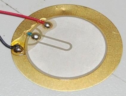
ISSN: 2349-7300
                                           ISO 9001:2008 Certified
    International Journal of Innovative Research in Engineering & Multidisciplinary Physical Sciences
                                                     (IJIRMPS)
                                       Volume 1, Issue 1, October 2013
COMPARATOR TL071:- The JFET-input operational amplifiers in the TL07x series are similar to the TL08x
series, with low input bias and offset currents and fast slew rate. The low harmonic distortion and low noise make
the TL07x series ideally suited for high-fidelity and audio preamplifier applications. Each amplifier features JFET
inputs (for high input impedance) coupled with bipolar output stages integrated on a single monolithic chip. The
C-suffix devices are characterized for operation from 0°C to 70°C. The I-suffix devices are characterized for
operation from −40°C to 85°C. The M-suffix devices are characterized for operation over the full military
temperature range of −55°C to 125°C.

Features:
1) Low Power Consumption.
2) Wide Common-Mode and Differential Voltage Ranges.
3) Low Input Bias and Offset Currents.
4) Output Short-Circuit Protection.
5) Low Total Harmonic Distortion . . . 0.003% Typ.
6) Low Noise Vn = 18 nV/√Hz Typ at f = 1 kHz.
7) High Input Impedance . . . JFET Input Stage.
8) Internal Frequency Compensation.
9) Latch-Up-Free Operation.
10) High Slew Rate . . . 13 V/μs Typ.
11) Common-Mode Input Voltage Range Includes VCC+.

(ii) 555 Timer:-The LM555/NE555/SA555 is a highly stable controller capable of producing accurate timing
pulses. With monostable operation, the time delay is controlled by one external resistor and one capacitor. With a
stable operation, the frequency and duty cycle are accurately controlled with two external resistors and one
capacitor.
Features:
•High Current Drive Capability (200mA).
• Adjustable Duty Cycle.
• Temperature Stability of 0.005%/°C.
• Timing from µSec to Hours.
• Turn off Time Less than 2µSec.

                                                  Fig. 2IC 555 Timer

(iii) CD4017 Decade Counter: The CD4017BM/CD4017BC is a 5-stage divide-by-10 Johnson counter with 10
decoded outputs and a carry out bit. The CD4022BM/CD4022BC is a 4-stage divide-by-8 Johnson counter with 8
decoded outputs and a carry-out bit. These counters are cleared to their zero count by a logical``1'' on their reset
line. These counters are advanced on the positive edge of the clock signal when the clock enable signal is in the
logical ``0'' state. The configuration of the CD4017BM/CD4017BC and CD4022BM/CD4022BC permits
medium speed operation and assures a hazard free counting sequence. The 10/8 decoded outputs are normally in
the logical ``0'' state and go to the logical “1'' state only at their respective time slot. Each decoded output remains

                                                          26
ISSN: 2349-7300
                                           ISO 9001:2008 Certified
    International Journal of Innovative Research in Engineering & Multidisciplinary Physical Sciences
                                                      (IJIRMPS)
                                        Volume 1, Issue 1, October 2013
high for 1 full clock cycle. The carry-out signal completes a full cycle for every 10/8 clock input cycles and is used
as a ripple carry signal to any succeeding stages.
Features:
1) Wide supply voltage range 3.0V to 15V.
2) High noise immunity 0.45 VDD (typ.).
3) Low power Fan out of 2 driving 74LS compatibility.
4) Medium speed operation.
(iv) Relay Switch: Relays are simple switches which are operated both electrically and mechanically. Relays
consist of a n electromagnet and also a set of contacts. The switching mechanism is carried out with the help of the
electromagnet. There are also other operating principles for its working. But they differ according to their
applications. Most of the devices have the application of relays.
The main operation of a relay comes in places where only a low-power signal can be used to control a circuit. It is
also used in places where only one signal can be used to control a lot of circuits. The application of relays started
during the invention of telephones. They played an important role in switching calls in telephone exchanges. They
were also used in long distance telegraphy. They were used to switch the signal coming from one source to another
destination. After the invention of computers they were also used to perform Boolean and other logical operations.
The high end applications of relays require high power to be driven by electric motors and so on. Such relays are
called contactors.
The TSOP 1738 is a member of IR remote control receiver series. This IR sensor module consists of a PIN diode
and a pre amplifier which are embedded into a single package. The output of TSOP is active low and it gives +5V
in off state. When IR waves, from a source, with a centre frequency of 38 kHz incident on it, its output goes
low. Lights coming from sunlight, fluorescent lamps etc. may cause disturbance to it and result in undesirable
output even when the source is not transmitting IR signals. A band pass filter, an integrator stage and an automatic
gain control are used to suppress such disturbances. TSOP module has an inbuilt control circuit for amplifying the
coded pulses from the IR transmitter. A signal is generated when PIN photodiode receives the signals. This input
signal is received by an automatic gain control (AGC). For a range of inputs, the output is fed back to AGC in
order to adjust the gain to a suitable level. The signal from AGC is passed to a band pass filter to filter undesired
frequencies. After this, the signal goes to a demodulator and this demodulated output drives an npn transistor. The
collector output of the transistor is obtained at pin 3 of TSOP module. Members of TSOP17xx series are sensitive
to different centre frequencies of the IR spectrum. For example TSOP1738 is sensitive to 38 kHz
whereas TSOP1740 to 40 kHz centre frequency.
(v) IR LED:An IR LED, also known as IR transmitter, is a special purpose LED that transmits infrared rays in the
range of 760 nm wavelength. Such LEDs are usually made of gallium arsenide or aluminum gallium arsenide.
They, along with IR receivers, are commonly used as sensors. The appearance is same as a common LED. Since
the human eye cannot see the infrared radiations, it is not possible for a person to identify whether the IR LED is
working or not, unlike a common LED. To overcome this problem, the camera on a cell phone can be used. The
camera can show us the IR rays being emanated from the IR LED in a circuit.

                                                   Fig. 3 IR LED

                                                         27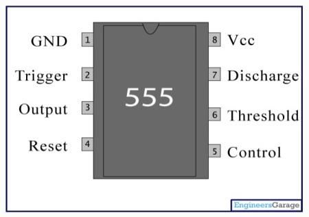
ISSN: 2349-7300
ISO 9001:2008 Certified
International Journal of Innovative Research in Engineering & Multidisciplinary Physical Sciences
(IJIRMPS)
Volume 1, Issue 1, October 2013
III. WORKING
When somebody touches our vehicles it produce vibrations, these vibrations are detected by piezoelectric crystal,
which is placed below the seat or connected to the vehicle body. Then it consist of comparator ,the output of piezo
electric crystal is given to comparator then it compare with reference voltage and produce a positive output
otherwise it will produce 0 output. The output of the comparator is much enough to start the transistor, and then
led connected to the emitter of the transistor. When output of the transistor is given to the 555 timer and it is the
property of the 555 timer ,when its pin 2 become high then pin 3 become low and pin 4 and 8 connected to the vcc
and pin 1 and 5 is grounded. when pin 3 become high then its is given to the Johnson counter as a clock then
counter will start 0 and 1 count output will not work because its output is given to the FET.Then for next count
LED will glow ,for 2 LED D3 will glow similarly for clock 3 and 4 D4 and D5 will glow Then it will give feed
back to the counter And it will give warning by sairon for 3 Then for next count it will be grounded through
transistor. Then full voltage is given to the relay 1 and due to the induction rod will come to it then it will cease
the ignition of vehicle.
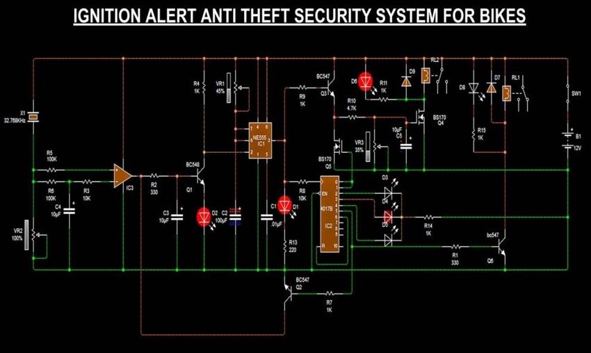
IV. CIRCUIT DIAGRAM AND PCB LAYOUT
Fig. 4 Circuit Diagram
Fig. 5 PCB OF MAIN UNIT
28ISSN: 2349-7300
ISO 9001:2008 Certified
International Journal of Innovative Research in Engineering & Multidisciplinary Physical Sciences
(IJIRMPS)
Volume 1, Issue 1, October 2013
V. CONCLUSION
This invention provides the better security as it works as alarming system simultaneously with the ignition ceasing
system. The simplicity and its economical factor can make it feasible. In other words we can say that this research
t is commercial level project. It is useful in Two-wheeler systems for safety proposes that’s why it is named as
Ignition Alert Anti-Theft Security System for Motorbikes with Remote Control. It follows the operation as their
name.
29You can also read