Implementation of a Novel Powered Ankle-Knee Prosthesis for Lower Limb Amputees and a Control Strategy Proposal
←
→
Page content transcription
If your browser does not render page correctly, please read the page content below
International Journal of Engineering and Advanced Technology (IJEAT)
                                                                                                  ISSN: 2249 – 8958, Volume-4 Issue-5, June 2015

 Implementation of a Novel Powered Ankle-Knee
Prosthesis for Lower Limb Amputees and a Control
                 Strategy Proposal
                             Ruben C. Martinez, Roberto L. Avitia, Marco A. Reyna, Miguel M. Bravo

Abstract— In this work we present the second stage of a powered                                   Continuing with this research we present here a control
ankle-knee prosthesis design and construction for individuals                                     strategy that can make possible the actuation of the powered
with a lower limb amputation. The prosthetic leg is composed of
                                                                                                  ankle-knee prosthesis. In order to improve the performance of
two modules; the knee module and ankle module, they can
operate independently or in conjunction. The ankle module is                                      the prosthesis we made some changes in the original design.
comprised of a unidirectional spring configured in parallel with a                                For example we replaced the clutch system for a linear
linear actuator. This spring is intended to store energy in                                       solenoid actuator that makes possible to have a more reduced
dorsiflexion, and then released it to assist power plantar flexion.                               overall-length. These changes are described next in section 2.
The knee module consists of a series elastic actuator and a linear                                These new changes permit to have a complete prosthesis that
solenoid actuator attached to the actuators transmission. Also we
are presenting a control strategy of the prosthesis, using
                                                                                                  include both modules in a lighter stiffer structure and a control
techniques of force, position and impedance.                                                      unit that will permit to create leg healthy movements during
                                                                                                  normal gait.
Index Terms—Powered Prosthesis, Mechanical Design, Lower
Limb Amputees.
                                                                                                                  II. PROSTHESIS DESIGN
                             I. INTRODUCTION                                                      The Prosthetic leg proposed is divided in two sections, which
Individuals with lower limb amputation have shown to                                              are the knee and the ankle module. Both modules are able to
expend more metabolic energy than an individual with a                                            work in conjunction and also operate independently. The
healthy leg during normal walking. Transfemoral amputees                                          purpose for which it was designed in a modular way is for a
expend up to 60% more metabolic energy compared with                                              wider range of amputees have the opportunity to use this
healthy subjects [1]. A transtibial amputee tends to expend                                       prosthetic device. Therefore it could be used by a transtibial
20-30% more metabolic energy in normal walking [2]. Thus,                                         amputee, as well as individual with a transfemoral
both cases of amputation tend to walk more slowly than an                                         amputation. The prosthesis was designed in the CAD software
individual with healthy lower limbs. In addition amputees                                         SolidWorks®. In the Figure 1 and Figure 2 we can appreciate
exhibit asymmetric gait patterns compared to non-amputees                                         all the mechanical components and parts of the sensors that
[3]. Currently most of the commercial prostheses available                                        comprise the prosthesis. The structure of both modules is
are passive prostheses. These are not able to bring positive                                      made of Aluminum 6061-T6 with an anodized treatment in
work at phase stance, also have increased the risk of joint and                                   order to increase the resistance to abrasion and to protect it
back pains. Some researchers have shown that powered                                              from chemical agents and environmental threats. On the other
prostheses for lower limb are able of mimic human gait. They                                      hand in order to avoid increase the weight of the prosthesis,
can provide negative and positive work in the stance phase, as                                    we are considering using a 3D printer to make the structure
wells as to improve amputees performance in a more natural                                        that will store the electronics and the battery source, and will
gait and normal walking [4]. Ideally, a good design of                                            place at the sides and on the back of the both modules. The
prosthesis needs to have some characteristics described as: (1)                                   prosthesis parameter ranges was established as close as
be able to produce net power to the gait (2) the lowest possible                                  possible to the leg-human range motion during level-ground
energy consumption, and (3) should not exceed the weight                                          walking, as we can see in Table I.
and the height of the missing limb. In this work we are                                             Table I. Physical parameters of the powered ankle and
presenting the second stage of a prosthesis design developed                                                       knee prosthesis modules.
previously [5] and in which we described the mechanical
design of the overall prosthesis.

Revised Version Manuscript Received on June 28, 2015.
  Ruben C. Martinez, Technological Institute for Rehabilitation,
Mexicali, Mexico.
  Roberto L. Avitia, Department of Bioengineering and Environmental
Health, Autonomous University of Baja California, Mexicali, Mexico.
  Marco A. Reyna, Department of Bioengineering and Environmental                                  2.1 The Knee Module Implementation
Health, Autonomous University of Baja California, Mexicali, Mexico.
  Miguel E. Bravo, Department of Bioengineering and Environmental
                                                                                                  In this section we describe the mechanical components that
Health, Autonomous University of Baja California, Mexicali, Mexico.                               comprise the knee prosthesis. In the normal level-ground
    *This work is supported by Technological Institute of Rehabilitation as part of the project   walking and specifically in the phase stance that takes 40% of
Bio-Prosthesis.

                                                                                                                Published By:
                                                                                              174               Blue Eyes Intelligence Engineering
                                                                                                                & Sciences Publication Pvt. Ltd.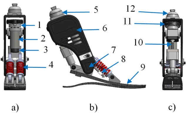
Implementation of a Novel Powered Ankle-Knee Prosthesis for Lower Limb Amputees and a Control Strategy
Proposal
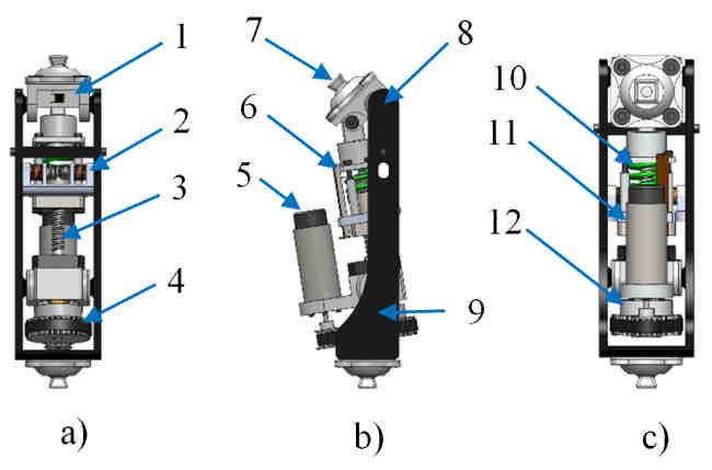
the gait cycle the torques generated by the knee presents the spring is to supplement the power output during plantar
almost linear behavior. The greatest demand of mechanical flexion. The parallel spring is unidirectional, and it is used
power during the gait cycle is presented in the phase stance only to provide stiffness when the ankle angle is greater than
[1]. The behavior of a spring is linear. Therefore choosing a zero. As same as the knee module a linear potentiometer
spring with the correct stiffness the prosthesis can achieve the (mark 8) is attached to the spring to measure the spring
linear region in the phase stance and approximate to represent deflection. At the top of the structure (mark 6) we placed a
the torque behavior of a healthy knee in the gait cycle. The structure that has an array of strain gage (mark 5) an also this
series elastic actuator (SEA) uses a brushless DC motor (mark structure is able to attach the pyramidal connector (mark 12).
11) (Maxon® EC-4pole 30,200 Watts) with a high resolution Figure 2 shows a three different angle representation of the
encoder (mark 5) (Maxon® Encoder MR type ML) attached ankle module with legends.
to the shaft. The actuator features transmissions comprises of 2.3 Control Strategy Proposal
timing belt pulley (mark 12), timing belt (mark 4) with a 3:1
We defined the control strategy as the architecture that
ratio, coupled to a ball-screw (mark 3) (NSK®,10 x 3 mm) in
governs the prosthesis and this is composed by different
series with a spring (mark 10) with a stiffness constant of 280
devices such as; sensors, drivers, actuators, microcontrollers
kN/m.
and algorithms that are integrated in a single box and are able
to recognize the gait patterns and commands demanded by the
user. In Figure 3 we represented diagram that represents our
control strategy. All information obtained by the sensors are
acquired by a microcontroller and then processed in a
computer algorithm. In this section we describe all devices
included in this control system as well as the action related.
Figure 1. CAD model of knee module with three different
angle representations. a) Front, b) Side and c) Back view
with a rotation angle of 0º, 45º and 90º respectively.
A linear potentiometer (mark 6) is placed in parallel to the
spring in order to measure the deflection of the spring and Figure 2. CAD model of ankle module with three different
obtain the force applied to the prosthesis. In the first design angle representations. a) Front, b) Side and c) Back view
we proposed to add a clutch in series to the SEA but then we with a rotation angle of 0º, 45º and 90º respectively.
realized that the overall-length and the weight of the
prosthesis was increase significantly. Hence, we decide to 2.3.1 Sensors System
redesign the model and replaced the clutch by a linear The sensing system or the recognition sensors system is
solenoid actuator (mark 2) that is attached to the transmission comprised by devices that measure different physic
of the SEA. On the top of the chassis (mark 9) is place a magnitudes. We established The Inertial Measurement Unit
moment load cell structure (mark 1) and also form part of the (IMU) that is integrated by 3 axis gyroscopes, 3 axis
joint [mark 8] of the prosthesis. There is attached the accelerometers and 1 compass. By applying the mathematical
pyramidal connector (mark 7) which will connect to the Euler algorithm we calculated the yaw, pitch and roll angles.
socket of the amputee as shown in Figure 1. With these information it was possible to determinate the
2.2 The Ankle Module Implementation prosthesis orientation. Also we can to interpret these
parameters and to estimate the action required by the
The Ankle prosthesis is composed of an actuator in parallel
individual. Electromyography (EMG) is an optional way to
with a unidirectional spring, best known as Parallel Elastic
control the activities that performs the prosthetic device. It
Actuator (PEA). For driving system, we used a brushless DC
makes possible the interaction between the user and the
motor (mark 2) (Maxon®, EC-4pole 30, 200 Watts) that has
prosthesis, permitting volunteer movements. Therefore it is
attached to the shaft an encoder (mark 3) (Maxon® Encoder
possible to establish a more natural interface
MR type ML). The motor drives a ball-screw (mark 10)
individual-prosthesis. The control of prosthesis by the EMG
(NSK®, 10x3 mm) via timing belt pulley (mark 1), and a
can be made establishing a series of commands that measure
timing belt (mark 11) with a 3:1 ratio. The ball-screw is
his pulse duration, amplitude and the sequence of the signal.
coupled in series with low profile prosthetic foot [mark 9]
The load cells are strategically positioned on the device, thus
(Ossur®, Flex foot). We used this elastic leaf spring to
each module includes a uniaxial load cell (Omega®). Since
emulate the function of a human foot. It provides shock
impedance changes in a strain gages are very small, they were
absorption and minimizes the ground reaction shock to the
connected into a Wheatstone bridge circuit in order to
transmission. The ankle actuator incorporates two springs
increase the sensibility to voltage changes. The configuration
(mark 4) with an individual stiffness of 162 KN/m that are
of the bridge is a quarter-bridge with temperature
positioned in parallel with the actuator. The purpose to add
compensation. We connected this output-bridge to high gain
Published By:
175 Blue Eyes Intelligence Engineering
& Sciences Publication Pvt. Ltd.
International Journal of Engineering and Advanced Technology (IJEAT)
                                                                          ISSN: 2249 – 8958, Volume-4 Issue-5, June 2015

instrumentation amplifier and a 2nd order low pass                 person could make such as hiking stairs or walking over flat or
Butterworth filter with a cutting frequency of 160 Hz that         inclined surfaces. Thus is essential that the prosthesis can
ensure a better signal to noise ratio. The information obtained    performs at least these activities. The torque, angle
by this sensors permits to obtain the applied force to the         movement, and cadence variations are parameters that change
prosthesis and consequently to determinate the sagittal            according to the activity developed for a healthy individual.
moment.                                                            Therefore knowing the action that an individual desires to do
2.3.2 Recognition of Action                                        it will depend the type of control that will be executed.
We defined the recognition of action as daily activities of a

                                 Figure 3. Control Strategy proposed consists of three different sections.

2.3.3 Control System                                               synchronized with the control system in order to manipulate
                                                                   the prosthesis movements. We used two shunt resistors as
The control system is comprised of a series of selectable
                                                                   motor current sensors due to their low cost good stability and
control techniques that are activated according to the action
                                                                   easy implementation. On the other hand a Hall Effect sensor
required in the gait. We used a Maxon ® Controller ESCON
                                                                   was attached to shaft motor in order to control the speed.
50/5 servo controller that includes a Current and Speed
control. Using these controllers was possible to find out the
                                                                                           III. RESULTS
force applying Equation 1. Where τ represents the applied
torque in N/m, I represents the current through the motor in       A real view of the prosthesis designed and new mechanical
Amperes and Kt represents the constant torque of the motor         changes are shown in Figure 4. We can appreciate the
(0.359 Nm/A) as shown en Equation 1. This control is applied       complete prosthesis for individuals for complete amputations
in activities that demand higher efforts such as stance phase      and separated modules for individuals with partial
(push off), no matter whether is walking at level ground or        amputations. Complete results are considered will be
running, this type of controller is always applied meanwhile       presented after the implementation of control systems.
the individual wants to take off the foot prosthesis from the
ground. On the other hand position control ensures the
moving joints with different angles. We used as position
control the high resolution encoder Maxon® MR type ML
1000 CPT attached to the shaft of both motors. The pulses of
the encoder signal are directly related to the joint position.
The impedance control is a hybrid control that permits the
interaction between the individual and the environment; it
comprises a position and a force control. This control is
essential and provides to the prosthesis a joints impedance
variable. This variable impedance is related with motor
parameters such as damping and inertial behavior.
   τ = Kτ × I                                              (1)
Once we know the torque we can calculate the mechanical
power as:
   Pm = τ × ω                                              (2)
Where   Pm is the mechanical power produce by the motor is,
τ is the torque and ω is the angular velocity.
2.3.4 Feedback Sensors System                                             Figure 4. A real presentation of the complete
The feedback sensors are a group of sensors that are                                        prosthesis.

                                                                                 Published By:
                                                                 176             Blue Eyes Intelligence Engineering
                                                                                 & Sciences Publication Pvt. Ltd.
Implementation of a Novel Powered Ankle-Knee Prosthesis for Lower Limb Amputees and a Control Strategy
                                                    Proposal

                         IV. CONCLUSION                                        modeling of HRECGs, development of medical instrumentation, and pattern
                                                                               recognition in biomedical images.
We have designed a powered and human-like prosthesis
similar in weight, size and functionality. The addition of
                                                                                                    Marco A. Reyna received the B.S. degree in electrical
elastic elements to the design of the prosthesis contributed to
                                                                                                    engineering from Autonomous University of Baja
enhance the performance of the device by increasing the                                             California (UABC)-Mexicali, Mexico, in 1990. He
bandwidth force, and the tolerance to the impacts generated                                         Received the M.S. degree in biomedical engineering
by the heel strike. The solenoid locking mechanism attached                                         from Metropolitan Autonomous University-Mexico
                                                                                                    D.F., in 1994, and the Ph.D. degree in bioengineering
at the transmission of the knee allowed reducing the energy                                         from the Polytechnic University of Cataluña, Barcelona,
requirements by the actuator. Thus, it contributes to the motor                Spain, in 1998. From 1988 to 1989, he was an electrical technician at the
life time. The overweight that presents the active prosthesis                  International Circuits enterprise in Mexicali, B.C., Mexico, where he
                                                                               performed the electrical test of different electronic products. In 1989 he was
are a big challenge that has not been resolved yet. Therefore,                 hired by the UABC, in Baja California, Mexico, where he has taught
we will need to replace the springs at the ankle by a composite                undergraduate and graduate courses, managed several research projects,
leaf spring and a new design that considers reducing                           published scientific articles in various journals, published book chapters,
                                                                               and a book, all related to bioengineering and environmental health. He was
considerably the weight of the prosthesis.
                                                                               the creator of the bioengineering and environmental health laboratory and
                                                                               one of the creators of the bioengineering undergraduate degree program. Dr.
                        ACKNOWLEDGMENT                                         Reyna currently is full researcher at UABC, leader of the bioengineering and
                                                                               environmental health research group and member of the National System of
We want to thank to students Luis R. Fierro and Hector                         Researchers.
Mayagoitia who collaborated intensively with this project as
research assistants.
                                                                                                     Miguel E. Bravo received his B.S degree in
                                                                                                     electromechanical engineering in 1983 from the
REFERENCES                                                                                           Autonomous University of Baja California.            He
[1]   D. A. Winter, 1991. The Biomechanics and motor control of Human                                received his M.S. degree in electrical engineering from
      gait: Normal, elderly and pathological, Waterloo Biomechanics, vol. 2.                         San Diego State University in 1991. And He received a
[2]   G. R. Colborne, S. Naumann, P.E. Longmuir, and D. Berbrayer, 1992.                             Ph. D in bioengineering by the University of California,
      Analysis of mechanical and metabolic factors in the gait of congenital                         San Diego, United States in 2001. His past employment
      below knee amputees: A comparsion of the SACH and Seattle feet,          includes technical support engineer in a computer manufacturing company,
      Ammer. J. Phys. Med. Rehabil.,vol. 71 no. 5, pp. 272-278.                research assistant in the Bioengineering Department at UCSD and professor
[3]   E.J. Rouse, L.M. Mooney, E.C. Martinez-Villalpando and H. M. Herr,       at the Faculty of Engineering UABC since 1986. Dr. Bravo has received
      2013. A clutchable series-elastic actuator: design of a robotic knee     multiple recognition such as "Space Act Award", awarded by the US Agency
      prosthesis for minimum energy consumption. IEEE International            Aeronautics and Space Administration (NASA), April 19, 2007, related to
      Conference on Rehabilitation Robotics.                                   the research work on multiparallel three dimensional optical microscopy and
[4]   Au, S.K., Weber, J., and Herr, H., 2009. Powered Ankle-Foot              the CONACyTrecognition for achievements in conducting original research
      Prosthesis Improves Walking Metabolic Economy, Robotics, IEEE            (2004 - 2010). He is one of the creators of the undergraduate program of
      Transactions. 25, (1), pp. 51-66.                                        Bioengineering that started in 2009, and now is responsible for leading
[5]   R. C. Martinez, R L. Avitia , M. A. Reyna, 2014. A Low Cost Design of    efforts to obtain approval from the accreditation board. His research interest
      Powered Ankle-Knee Prosthesis for Lower Limb Amputee:                    and teaching relates to digital signal processing, biomedical instrumentation
      Preliminary Results, In Proceedings of the International Conference on   and automated vision systems.
      Biomedical Electronics and Devices, pp. 253-258.

                   Ruben C. Martinez received a B.S. degree in
                   bioengineering and biomedical instrumentation
                   specialization from the Autonomous University of Baja
                   California (UABC), Mexico in 2013. He is the first
                   student graduated from bioengineering program of
                   UABC Mexicali. His past employment includes
                   assistant researcher at UABC and Hospital Experience
as biomedical engineer at General Hospital of Mexicali. He is Co-Founder
of the Technological Institute for Rehabilitation (ITR). Mr. C. Martinez is
currently part time employee at Markel Corp. as design engineer and
president of ITR Foundation. His interests include development of
electromechanical prototypes for rehabilitation and biomedical
instrumentation.

                      Roberto L. Avitia received the B.S degree in
                      biomedical electronic engineering from National
                      Technological of Mexico in 2004, his M.S. degree in
                      bioelectronics from the Center for Research and
                      Advanced Studies of the National Polytechnic Institute
                      in 2006 and the Ph.D. in biomedical engineering from
                      Autonomous University of Baja California (UABC) in
2013. His past employment includes industrial at Hirata Engineering and
hospital experience at National Institute of Cardiology. He joined the
Department of Bioengineering and Environmental Health at UABC in 2007
by applying dynamic programming and machine learning algorithms in high
resolution electrocardiography (HRECG). He is one of the creators of the
bioengineering undergraduate program at UABC. Dr. L. Avitia is currently
full professor of the bioengineering program of the UABC and member of
the National System of Researchers. His research interests include nonlinear

                                                                                                Published By:
                                                                           177                  Blue Eyes Intelligence Engineering
                                                                                                & Sciences Publication Pvt. Ltd.
You can also read