Implementing Laser Scanned-MEMS Projection in Automotive Head-Up Displays
←
→
Page content transcription
If your browser does not render page correctly, please read the page content below
Implementing Laser Scanned-MEMS Projection in
                 Automotive Head-Up Displays

Introduction
In 1988, the Oldsmobile Cutlass Supreme became the first production car with a basic head-up display, also
known as HUD. Automotive safety was and continues to be the main driving force for the deployment of
HUDs with the aim of preventing drivers from taking their eyes off the road to look down and read their
dashboard instruments. Distracted driver studies have shown that taking your eyes off the road for more
than two seconds doubles your risk of a crash. Over the last decade, HUDs have become more sophisticated
and increasingly available as standard or optional equipment in luxury car models from several automakers.
They represent the latest safety innovation, and have become part of an ever-increasing suite of advanced
driver assistance systems (ADAS).

The automotive HUD places key information such as speed, warning signals, and indicator arrows on the
windshield directly in front of the driver’s line of sight. One of the latest laser scanned-MEMS projection
systems uses laser diode drivers to pulse high intensity red, green and blue (RGB) lasers that project high-
definition (HD) video onto the windshield (see Figure 1). These new real-time laser systems enable HUD
information with virtually zero latency. Augmented reality HUDs appear to paint a transparent arrow directly
onto the street in front of the car, making color turning signals and navigation directions easy to follow. They
also highlight other objects, like pedestrians or vehicles that might present a hazard and brings them to the
driver’s attention.

This white paper looks at the history of optical MEMS systems and shows how the technical merits of a laser
scanned-MEMS projection system provide a superior, lower-cost solution than liquid-crystal display (LCD)
and digital light processing (DLP) HUDs. We’ll also examine a high-speed, quad-channel laser diode driver
that provides a complete solution for driving high intensity lasers in laser scanned-MEMS projection systems
designed for next-generation automobiles.

              Figure 1. Laser scanned-MEMS projection system for automotive head-up display

                                   1   Renesas Electronics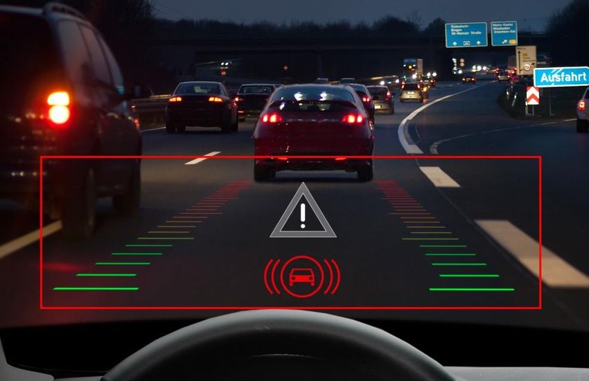
Optical MEMS: A Brief History
Optical MEMS has been around since the early 1980s with the first patent filed by Texas Instruments for the
deformable mirror light modulator. Since then, one of the major applications for MEMS mirrors has been in
the display market. Every time we enjoy a movie at the digital cinema theater, we see this technology at
work.

Since their introduction, the physical size of MEMS projection systems has experienced several
transformations. System size has shrunk from the large cinematic projector to the office projector and more
recently, the palm size pocket-projector. This change came about due to advances in electronics integration,
ultra-small IC packaging, and light source advancements. All of these innovations enable products with
integrated projection displays such as Microvision’s PicoP, Samsung’s Galaxy smartphone, Lenovo’s Yoga
tablet, and now automobiles with HUDs using laser scanning MEMS technology.

For a brief time, DLP systems dominated the large-screen, rear-projection display market, but DLPs
dominance met tough new competition with the introduction of flat panel thin-film-transistor (TFT) displays.
Similarly, the use of DLP-based HUDs in the automotive market is now facing stiff competition from the
maturing and availability of single-pixel scanning MEMS projection displays. The key factors that give
scanned-MEMS such a boost are the wide availability of laser diodes, higher integration of electronics, and
lower cost optics.

Previously, RGB laser diodes had been cost-prohibitive to the adoption of laser scanned-MEMS projection.
Today, with several manufacturers such as OSRAM, Nichia, Cree, Panasonic, Philips and others, the cost of
laser diodes has been reduced to an acceptable level for automakers. In addition, some of these
manufactures are making automotive-grade AEC-Q100 certified laser diodes. And these RGB laser diodes
are now integrated into a monolithic module where the beam alignment is handled during module
manufacturing, making it much easier for system designers to integrate the module into their HUD design.

Until now, most MEMS mirror manufacturers used a mature ASIC design that performs the driving function
for their MEMS. However, to interface with the laser diode, HUD designers had to rely on discrete
components. Each color channel required its own discrete laser driver, resulting in a rather large PCB
surface area. This made the board design and thermal management more challenging for the system
designer. But with the recent introduction of a quad-channel automotive-grade laser diode driver capable of
full-HD pixel rates, it is now possible to pack the entire system into a small, compact area.

Comparing Laser Scanned-MEMS Projection with LCD and DLP
The LCD display panel is probably the most commonly used technology in today’s automotive HUD systems.
It employs a transmissive display technology and LED backlights that illuminate the entire image when light
passes through it. With LCD HUDs, the image is first loaded into the LCD and is then illuminated by high
power LEDs. The illuminated image is magnified, reflected off a fold mirror and focused onto the windshield
in front of the driver’s field of view.

The LCD HUD’s dark pixels are created by blocking the backlight, which makes the LCD less transmissive for
those pixels. However, not all light can be completely blocked, especially in low ambient light settings. The
result is a projected image overlaid onto the windshield that looks like a transparent postcard sized
rectangle (see Figure 2). Automakers see this as a major safety drawback of today’s LCD HUD systems
because the illuminated rectangle is a distraction to the driver.

Today’s LCD-based HUDs have a limited field of view, and the LCD panel has limited resolution, which makes
it harder to provide more information for the driver to see. For an increased field of view, a larger LCD panel
would be required. Finally, to meet the augmented reality requirement, the HUD would need to have much
higher resolution. Both the increased panel size and higher resolution present an additional design

                                  2   Renesas Electronics
challenge: more electrical power (greater than 80W) is required to light the panel. This is moving in the
reverse direction of the automaker’s goal to reduce power consumption and size, and to implement
augmented reality safety advancements. Thus, the LCD is not a viable technology for next generation HUDs.

                                          Figure 2. LCD HUD example

DLP, the other competing HUD technology, is similar to LCDs but offers better resolution. DLP has thousands
of micromirrors arranged in a two-dimension (2D) array. Each mirror in the 2D array serves as a pixel, and
each mirror is modulated to reflect the incident light to create the desired pixel intensity. A 100% bright pixel
will have zero modulation, while a dark pixel will have the mirror set to reflect the light out of the imaging
path. To give a uniform image result, the incident light source is collected and focused onto the 2D array,
with equal intensity on each pixel. The reflected image is then magnified, refocused and projected to a
folding mirror, and then onto the windshield, a process similar to the LCD HUD implementation.

DLP is a rectangular panel that requires a flat horizontal surface to project information. Windshields are
relatively flat in the vertical direction, but not in the horizontal direction. Therefore, for DLP to place
information onto the windshield, aspherical optics is required to accommodate the windshield’s curves,
which requires increasing the size of the HUD system solution.

DLP HUDs also employ LEDs as their primary illumination light source. Because LEDs are a lambertian light
source, designers use specialty optics to optimize light efficiency and uniformly radiate each pixel with equal
intensity to best fit the Etendue of the DLP panel. While DLP has less optical power loss when compared to
transmissive LCDs, the LEDs employed still consume a significant amount of electrical power.

Compared to DLP systems, a laser scanned-MEMS projection system takes advantage of the scanning
mirror’s deformed image, enabling the use of lower cost optics to reduce the system’s opto-mechanical cost.
The main components of a laser scanned-MEMS system are the laser diodes, some small beam shaping and
alignment optics designed to gather the different color beams into uniform shaped single beam, and the
oscillating MEMS mirror and its control electronics. The color laser diodes are pulsed synchronously as the
mirror is scanned across the display field. The image is then drawn pixel-by-pixel across the display field,
which is overlaid onto the windshield.

In a laser scanned-MEMS projector, each pixel is pulsed very rapidly to create the full HD resolution. And,
because the laser beam is always in focus, the image can be projected into the windshield without requiring

                                   3   Renesas Electronics
refocusing optics. This greatly reduces the overall optical system complexity and size, and it eliminates costly
optical components and assembly.
Laser scanned-MEMS projection systems offer better overall electrical efficiency than LCD or DLP frame-
based projection systems. Unlike a front projector where the entire display is filled with a presentation, the
automotive HUD’s navigation information and instrument information do not fill the entire HUD field display
area. The HUD system presents only time-sensitive information on the windshield for a short duration of
time. The augmented reality information is comprised of an image that can have over 70% of the display
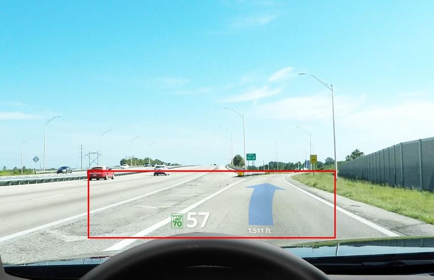
pixels turned off. Figures 3A and 3B show examples of HUD information. The red boxes in Figures 3A and 3B
show typical HUD display areas where the projection system must be able to present the navigation
information. Note the amount of pixels turned ON relative to the amount turned OFF in each example.
Depending on the information, that ratio (ON:OFF pixels) can range anywhere from 1:3 to 1:6.
Figure 3A. Typical HUD output example
Figure 3B. HUD information example
4 Renesas Electronics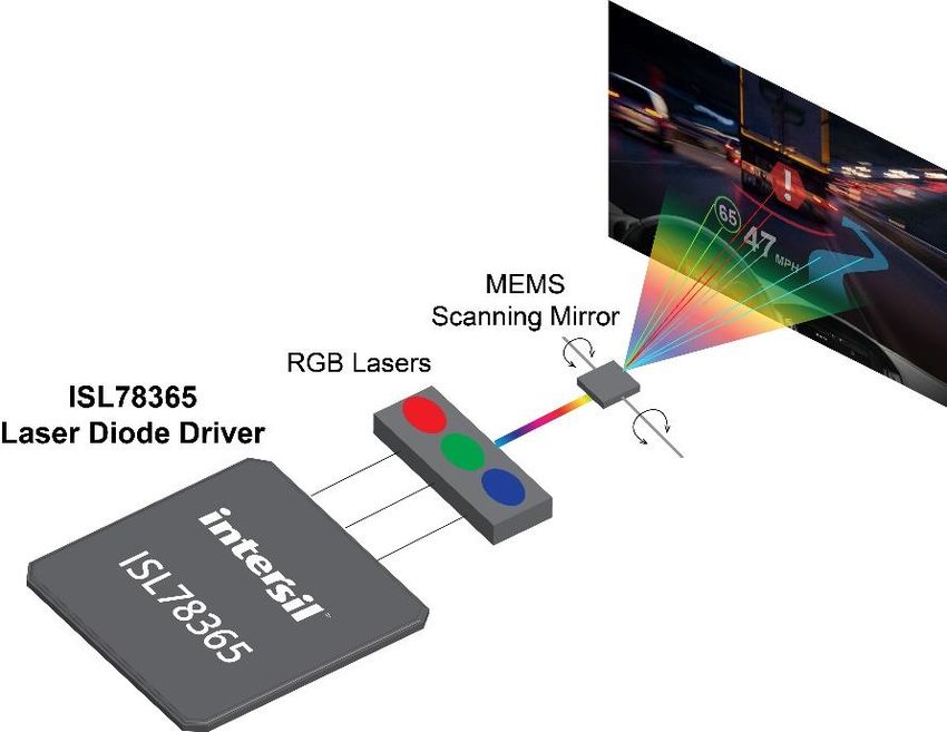
For example, in the DLP frame-based display technology, regardless of how many pixels are turned ON, the
light source must fill the entire pixel array. In Figure 3A, the light for “dark” or not turned on pixels in the red
box display area is generated and then discarded either by reflecting it away from the area of view or by
blocking it. This is energy consumed that counts against the HUD’s system efficiency. Even worse is that this
lost energy contributes to additional heat generated by absorption of the redirected light and the cost of
electrical energy to create the light in the first place. These two factors ultimately increase the frame-based
thermal cooling requirement and electrical energy needs.

A laser scanned-MEMS HUD consumes electrical power when there are relevant pixels to be projected. With
the typical navigation and instrumentation information as shown in Figures 3A and 3B, most of the electrical
energy is consumed when there is a need to put a pixel onto the display. This dramatically reduces the
electrical requirement, resulting in lower thermal profile and thus smaller thermal dissipation requirements.
All of this, combined with the integration of driver electronics, results in an overall smaller projection
footprint when compared to a frame-based HUD system.

With pixels turned off, the laser scanned-MEMS HUD does not create a postcard effect because only the
pixels with information are illuminated. Where no information is presented, no light is projected and no
power is wasted. Combined with the deformation mirror effect and the more compact size, the laser
scanned-MEMS HUD is best suited for the next generation of augmented reality HUD systems.

High-Speed, Quad-Channel Laser Diode Driver
The ISL78365 laser diode driver is the first four-channel driver optimized for HD laser scanned-MEMS
projection systems that help deliver augmented reality video information to the automobile windshield. The
laser driver includes an interface that easily integrates with the MEMS ASIC to create a compact laser
scanning projection system, as shown in Figure 4.

            Figure 4. ISL78365 quad-channel laser driver pulsing four high-intensity laser diodes

The ISL78365 provides four high-speed 750mA programmable current sinks, which regulate the current and
optical output of up to four laser diodes. It provides 1.5ns rise and fall times, resulting in high frame rate, HD
color video, as illustrated in Figure 5. The laser driver offers independent color, threshold, and scale settings
for each current sink, and its flexible high-speed parallel video interface supports full-HD projection and pixel
rates up to 150MHz or 1900 pixels per line. It includes multiplexing of pixel data to simplify the opto-
mechanical to electronic layout requirement.

                                    5   Renesas Electronics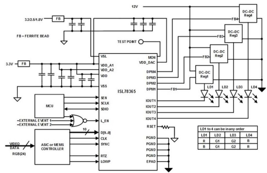
Figure 5. Laser head-up display presents full-HD video information in car driver’s line of sight

Dynamic power management for each laser diode supply and three power saving modes further reduce total
system power consumption during blanking time. The laser driver’s programmable return-to-zero pulsing
functionality de-speckles the displayed image, and a programmable over-temperature protection enables
customized thermal performance of the laser diodes. The ISL78365 is the first AEC-Q100 Grade-1 qualified
laser driver, and is packaged in a wettable flank QFN package, making it easier for automakers to integrate
into their system and manufacturing process.

Most RGB image processors have the color data image processed in the R, G, and B order. Thus, data
presented to the MEMS laser driver is also in that order. This presents a design challenge because
maintaining the optical laser-diode-illumination module in the same order can result in opto-mechanical
compromises that result in lower lumens output, or a larger laser illuminator, or having to add additional
laser diodes to compensate for the lower lumens. The ISL78365 data input interface overcomes this issue
with its integrated multiplexer bus that simplifies the complex routing of the RGB data bus to the
illuminator’s opto-mechanical module.

Driving a good quality image requires control of the current pulse to the laser diode. Ideally, the waveform
should be a square wave with an infinitely fast rising and falling edge, and a flat top during the pulse period.
Such an ideal waveform does not exist in practice. With some laser diode drivers, fast transition pulses
result in overshooting the rising edge of the drive current. The large overshoot exhibits itself in a pixel with a
slightly brighter edge. If every pixel on an image has a slight bright edge, it produces undesirable image
quality not suitable for the automotive laser HUD.

The ISL78365 provides adjustments to help compensate for this overshoot. Two compensations are
possible: one to compensate for the overshoot, and another to compensate for pulse flatness. Figure 6
shows a 20ns pulse, and while most HD resolution displays do not have a 20ns pixel duration, we have
chosen this pulse width to demonstrate the ISL78365’s ability to compensate for pulse flatness. Because
the overshoot is a function of the laser diode and the PCB parasitic, each driver channel has its own
adjustment circuit, allowing the system designer to better tune to the different laser diode performances and
picture qualities.

                                   6   Renesas Electronics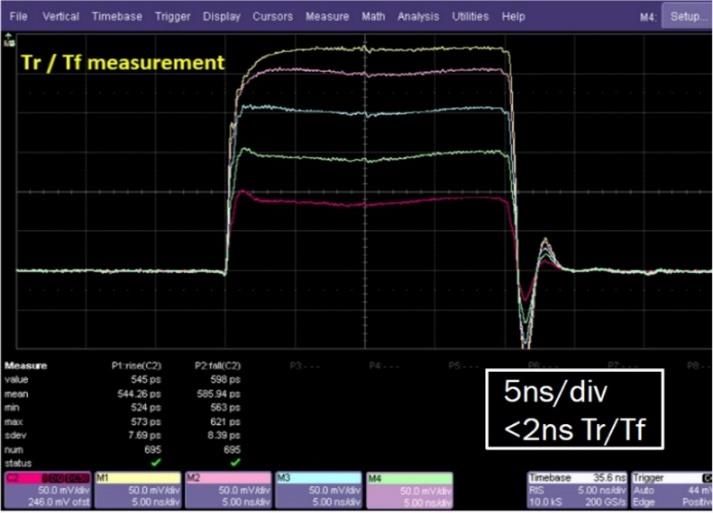
Figure 6. ISL78365 laser diode driver showing overshoot compensated pulse

Heat is another enemy of the HUD system. Excessive HUD system heat can damage the laser diodes and,
therefore, a larger thermal heatsink is required to protect the lasers. However, a large heatsink means a
larger cavity is required behind the dashboard, and that adds weight and more cost to the vehicle--all
contradictory to the automaker’s goal of a lighter and greener vehicle. The ISL78365 offers dynamic power
management to minimize excess power dissipation by optimizing the supplies for the laser diodes.

The ISL78365 also takes advantage of the need to place the laser diodes close to the driver itself, in order
to offer thermal protection for the laser diodes. This placement minimizes parasitic inductance and
capacitance on the current drive. An added benefit of placing the diodes near the laser driver is that it
results in a close thermal coupling between the ISL78365 IC and the laser diodes. Therefore, using a fixed
temperature offset, the ISL78365’s temperature will be close to that of the laser diode. And since the
system can monitor the temperature of the laser diode driver, it will know the approximate temperature of
the laser diodes.

The ISL78365 offers an integrated temperature monitor that is internally digitized, recording the die
temperature in an internal register. There is also a programmable over-temperature shutdown point, as well
as a programmable recovery temperature. By programming these registers, the system not only protects the
ISL78365 from overheating but also the laser diode. Since the laser diode operating temperature range and
lifetime vary from vendor to vendor, and are improving over time, the ISL78365’s programmable over-
temperature feature allows it to be customized to protect any laser diode.

Conclusion
The laser scanned-MEMS projection system is better suited for automotive augmented reality HUDs than the
alternative DLP or LCD frame-based display systems. It has the lowest thermal heat generation, and when a
laser HUD scanned image only has 25% to 30% of its pixels turned on, the DLP and LCD HUD will require
100% of its image pixels driven to generate the same amount of brightness (current) as the laser HUD. DLP
and LCD systems throw away light in order to display a black pixel, but with the laser scanned-MEMS
projection system, a black pixel is truly black because the laser diode is turned off and is not consuming
power or generating thermal heat.

The DLP and LCD optical architectures do not fully turn off a black pixel, so there is some level of leakage
due to the display panel’s surface reflectivity. This results in a slight bright spot where the black pixels area
should be. During daytime sunlight, this envelope might not be an issue, but at night, it is much more

                                   7   Renesas Electronics
apparent. From a driver safety perspective, it becomes another distraction, and tips the scale in favor of
automakers moving to the laser scanned-MEMS projection system for their next generation HUD.
Next Steps
Learn more about the ISL78365
Get the data short
Watch a demo video
###
About Renesas Electronics Corporation
Renesas Electronics Corporation delivers trusted embedded design innovation with complete semiconductor solutions that enable
billions of connected, intelligent devices to enhance the way people work and live—securely and safely. A global leader in
microcontrollers, analog, power, and SoC products, Renesas provides the expertise, quality, and comprehensive solutions for a broad
range of Automotive, Industrial, Home Electronics, Office Automation and Information Communication Technology applications to
help shape a limitless future. Learn more at renesas.com
+1 408-432-8888 | © Renesas Electronics America. All rights reserved. Renesas & Intersil (and design) are trademarks owned by
Renesas Electronics Corporation or one of its subsidiaries. All other trademarks mentioned are the property of their respective
owners.
8 Renesas ElectronicsYou can also read