INSTA-VALVE 20-24 INSERTION VALVES - 20"-24" Installation Instructions - Revised March 2021 - Hydra-Stop

 
CONTINUE READING
INSTA-VALVE 20-24 INSERTION VALVES - 20"-24" Installation Instructions - Revised March 2021 - Hydra-Stop
INSTA-VALVE 20-24 INSERTION VALVES
20”–24” Installation Instructions — Revised March 2021
INSTA-VALVE 20-24 INSERTION VALVES - 20"-24" Installation Instructions - Revised March 2021 - Hydra-Stop
20”–24” Insta-Valve | Installation Instructions | 2

                                                                                Table of Contents
Section 1 – General Safety Precautions
1.0.0 General Safety Precautions..................................................... 3
Section 2 – Valve Installation Guide
2.0.0 Preparation............................................................................. 5
2.1.0 Assembly of Valve Body and Cover.......................................... 5
2.2.0 Assembly of Valve Body.......................................................... 5
2.3.0 Assembly of Temporary Gate Valve and Adapter Flange.......... 5
2.4.0 Assembly of Adapter Flange (Only for 20-Inch Valve).............. 6
2.5.0 Hydrostatic Test...................................................................... 6
2.6.0 Tapping Procedure.................................................................. 7
2.6.1 Assembly of Tapping Machine................................................. 7
2.7.0 Performing the Tap................................................................. 8
2.8.0 Assembly of Valve Cartridge, Insertion Machine, and Insertion
Housing........................................................................................... 8
2.9.0 Assembly of Inserting Tool...................................................... 9
2.10.0 Inserting the Cartridge.......................................................... 9
2.11.0 Removal of Inserting Tool...................................................... 10
2.12.0 Removal of Insertion Housing............................................... 10
2.13.0 Placing the Bonnet Flange..................................................... 10
2.14.0 Removing the Temporary Gate Valve..................................... 10
2.15.0 Assembly of Side Lid And Operating Nut............................... 10
2.16.0 Removal of Valve Body Ball Valve.......................................... 10
2.17.0 Operating Turns.................................................................... 11
Section 3 – Appendices
Appendix A 20” and 24” Mounting Bolt Torque Tightening
Patterns........................................................................................... 13
Appendix B 20” Valve Excavation and Concrete Support Details....... 14
Appendix C 24” Valve Excavation and Concrete Support Details....... 15
Appendix D Seal Plug Remove and Replacement using the
Seal Plug Tool.................................................................................. 16
Appendix E Insta-Valve 20-24 Part Identification............................. 18
Appendix F Equipment Identification............................................... 19
Appendix G Standard Tools.............................................................. 21
Appendix H Side Tapping and Horizontal Bevel Gear use.................. 22

© 2021 Hydra-Stop | All Rights Reserved. | Specifications subject to change without notice.
INSTA-VALVE 20-24 INSERTION VALVES - 20"-24" Installation Instructions - Revised March 2021 - Hydra-Stop
20”–24” Insta-Valve | Installation Instructions | 3
Section 1.0.0 — General Safety Warnings                                               Check Hardware and Equipment
General Safety Precautions — Read and Follow                                          Make sure that all air or hydraulic line couplings are tightened
Instructions                                                                          and secured to eliminate the chance of accidental uncoupling.
Carefully read and understand all safety messages in this                             Use hose connection retaining devices such as locking rings,
manual before using the equipment. The manuals provided                               clips, pins, chains, or cables. Identify all equipment and tools
with the equalization pump must also be read for safety.                              necessary for the size of Insta-Valve 20-24 you intend to install.
The maintenance procedures are to be followed to keep the                             Please refer to the attached tool list ((see Appendix G). Inspect
equipment in good working condition.                                                  equipment to verify it is in good working condition and free of
                                                                                      wear and damage prior to use. Never start an operation if the
Personal Protection                                                                   equipment is not in proper working order. Contact Hydra-Stop if
                                                                                      equipment is not in working order.
Hydra-Stop recommends that installers wear required personal
protective equipment including but not limited to:
                                                                                      Do Not Exceed Load Rating on Any Lifting Equipment
    • Hard Hat
    • Safety Shoes                                                                    This includes but is not limited to lifting magnets, eyebolts and
    • Safety Glasses                                                                  straps. Lifting magnets provided with Hydra-Stop equipment are
    • Ear Protection                                                                  labeled with a load rating.
    • Gloves
Avoid wearing jewelry, such as rings, wristwatches, necklaces,                        WARNING: Failure to follow any of the above safety
or bracelets. If working near traffic, select ear protection that                     instructions or those that follow in this manual, could result
allows you to hear the traffic for safety.                                            in serious injury. Any operation involving work on pipe(s)
                                                                                      containing liquids under pressure is potentially hazardous. It
Keep Spectators Away from Installation Area                                           is necessary, therefore, that correct procedures be followed in
                                                                                      the use and maintenance of this equipment to maintain a safe
Keep all spectators and other workers away from machines and
                                                                                      working environment.
work area(s) while in operation.

Clear Work Area                                                                       No person should use this equipment who is not fully trained
Clear the work area of all objects that might interfere with                          in the procedures stated in this manual, and who is not fully
the proper operation of any tools. Avoid placing tools or other                       aware of the potential hazards connected with work on pipe
objects where they can fall into the pit.                                             containing liquids or gases under pressure.

Do Not Work in an Unsupported Trench                                                  The purchaser of this equipment is responsible for the manner
                                                                                      in which this equipment is used, maintained, and the training,
Do not work in a trench with unstable sides, which could                              competence and safety of the operators.
cave in. Specific requirements for shoring or sloping trench
walls are available from several sources including federal and                        Should any difficulty arise at any time in the use of this
state offices. Be sure to contact suitable authorities for these                      equipment, please contact Hydra-Stop at 708-389-5111
requirements before working in the trench. Locate the existing                        immediately.
pipe joints or fittings in the area and use the appropriate
restraint methods if necessary.                                                       NOTE: Do not completely close valve until valve has been
                                                                                      restrained with concrete or restraint clamps.
Check Laws and Regulations
Know and obey all Federal, State, and local laws and regulations
that apply to your work situation.

Handling the Equipment
To avoid back injury, use proper lifting techniques. Follow all
equipment instructions when lifting heavy loads.

© 2021 Hydra-Stop | All Rights Reserved. | Specifications subject to change without notice.
INSTA-VALVE 20-24 INSERTION VALVES - 20"-24" Installation Instructions - Revised March 2021 - Hydra-Stop
INSTA-VALVE INSERTION VALVES
Insta-Valve 20-24 Installation Instructions
INSTA-VALVE 20-24 INSERTION VALVES - 20"-24" Installation Instructions - Revised March 2021 - Hydra-Stop
20”–24” Insta-Valve | Installation Instructions | 5
Section 2 — Valve Installation Guide                                                                           2.2.4) Finger tighten the bolts with the
                                                                                                               nuts.
2.0.0 Preparation
2.0.1) Check the type of pipe, O.D., I.D., pressure, flow direction,                                           2.2.5) Put a level on the upper valve
and installation location prior to installation.                                                               body and tighten the hexagon bolts
                                                                                                               and nuts. Check level as you tighten.
2.0.2) Measure and confirm pipe outside diameter where the
Insta-Valve 20-24 is being installed to ensure the pipe meets the                                              CAUTION: Do not remove the lift
valve O.D. and I.D. range.                                                                                     support from the valve body until the
                                                                                                               mounting bolts and nuts are tightened
2.1.0 Assembly of Valve Body and Cover                                                                         and torqued. Releasing the load prior
                            2.1.1) Thoroughly clean the pipe surface                                           to tightening the nuts and bolts could
                            with a wire brush where the valve body                                             allow the valve body and sleeve to
                            will be installed to ensure all loose debris                                       rotate.
                            and material is removed (see Image 1).
                                                                                                               2.2.6) Using a torque wrench, tighten
                            NOTE: Inspect for flaws (ex. gouges,                                               nuts in proper pattern. Repeat
                            protrusions, excessive corrosion, etc.).                          Image 4          tightening pattern in no more than 25
                            Irregular surfaces should be avoided to                                            ft. lb. increments until recommended
                            assure maximum gasket sealing.                                                     torque is reached.

                            2.1.2) Utilizing safe lifting procedures                                           NOTE: Torque patterns are shown in
                            or equipment, position the valve sleeve                                            Appendix A — 20” and 24” Mounting
        Image 1            below the pipe.                                                                     Bolt Torque Tightening Patterns.
2.1.3) Cradle the valve sleeve so that it wraps around the                                                     NOTE: Torque of valve mounting bolts
bottom of the pipe.                                                                                            is: 105 ft. lbs.
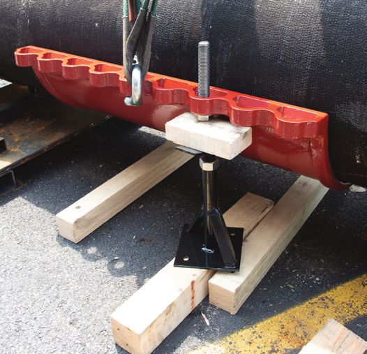
                                       2.1.4) Use screw-style jack                                             CAUTION: Be sure to check the
                                       stands or blocking to support                          Image 5          mounting nuts and bolts are properly
                                       the sleeve until it is secured to                                       tightened to specified torque to
                                       the valve body (see Image 2).                  prevent seal failure.
                                       NOTE: Use a base plate to keep                 2.2.7) Wait 10 minutes to allow the gasket to fully seat then
                                       jacks or blocking from sinking on              re-tighten bolts to the recommended torque THREE additional
                                       weak or saturated ground.                      times, following the tightening pattern.
                                       CAUTION: Do not remove the                     2.2.8) Check and readjust the support blocks or jacks under the
                                       lifting straps until the sleeve is             sleeve to be sure they are supporting the valve and pipe.
              Image 2                  secured in place with jacks or
                                       blocking.                                      2.2.9) Remove the lifting straps on the upper side of the valve
                                                                                      body.
2.2.0 Assembly of Valve Body
                                                                                      2.2.10) Remove set pin cover plugs.
                                        2.2.1) Before lifting and
                                        rotating the valve body into the                                            2.2.11) Wrap Teflon seal tape
                                        installation position, lubricate                                            on the set pin cover plugs and
                                        the surface of the rubber throat                                            re-install into the valve body (See
                                        gasket at around the valve                                                  Image 6).
                                        opening (see Image 3).
                                                                                                                    2.3.0 Assembly of Temporary
              Image 3                   NOTE: Lubricate the entire                                                  Gate Valve
                                        surface of the rubber ring with                         Image 6            2.3.1) Open the temporary gate
                                        the designated lubricant to                                                valve. Be sure to block under and
                                        prevent seal failure.                         support the gate (see Image 7 on next page).
2.2.2) Rotate the valve body into the mounting position and                           2.3.2) Lubricate the temporary gate valve gasket (whole surface)
lower the valve body onto the pipe (see Image 4 and 5).                               and the O-ring on the rectangular face of the temporary gate
                                                                                      valve flange.
2.2.3) Install mounting bolts to attach the sleeve to the valve
body.

© 2021 Hydra-Stop | All Rights Reserved. | Specifications subject to change without notice.
INSTA-VALVE 20-24 INSERTION VALVES - 20"-24" Installation Instructions - Revised March 2021 - Hydra-Stop
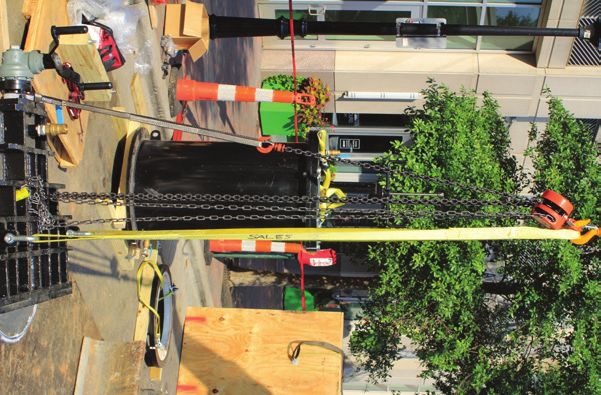
20”–24” Insta-Valve | Installation Instructions | 6

                                                                                                           2.4.2) Adjust and align the white line
                                                                                                           on the adapter flange with the white
                                                                                                           line on the valve body (see Image 13).

                                                                                                           2.4.3) Mount the adapter flange to the
                                                                                                           valve body with the supplied nuts and
                                                                                                           bolts.

                                                                                                           2.5.0 Hydrostatic test
                                    Image 7
                                                                                                           2.5.1) Remove the seal plug NPT cover
                           2.3.3) Lift the temporary gate valve using 3                                    plug using an open-ended wrench or
                           points of contact — 2 front locations and 1                        Image 12
                                                                                                           adjustable wrench (see Image 14).
                           back location (see Image 8).                                                    Place in a safe location for later use.
                           NOTE: Hydra-Stop recommends utilizing                                           See Appendix B for complete seal plug
                           a chain fall for the back lifting location to                                   tool setup and usage instructions.
                           adjust the level of the temporary gate valve
                                                                                                           2.5.2) Remove the seal plug using the
                           while being installed.
                                                                                                           Seal Plug removal tool. Place seal plug
                           2.3.4) Remove the nuts and bolts holding                                        in a safe location for later use.
                           the temporary gate valve cover in place                            Image 13
                           on the valve body. Remove the temporary                                         2.5.3) Assemble the drain parts as
        Image 8            gate valve cover. Keep the bolts and nuts in                                    shown (see Image 15). in the figure to
                           a safe location.                                                                the left, with the union fitting oriented
                                                                                                           down.
                                  2.3.5) Lift and move the temporary
                                  gate valve towards the temporary                                         NOTE: Be sure to install the short
                                  gate valve attachment port of the                                        nipple into the drain port, followed
                                  valve body. Level the temporary valve                                    by the ball valve, another nipple,
                                  with the chain fall (see Image 9).                                       the 90-degree elbow, and the union
                                                                                              Image 14     connection to ensure successful ball
                            2.3.6) Mount the temporary gate                                                       valve port completion plug
          Image 9           valve to the rectangle flange of the                                                  insertion completed in a later
                            valve body using the bolts (M16).                                                     step.
 Adjust the circular portion of the gate valve into the gate valve
 slot on the valve body until the flanges come into contact with                                                  2.5.4) Fill the valve body with
 each other.                                                                                                      10 to 15 gallons of water.

                                   2.3.7) Block and support below the                                             2.5.5) Using a lift, lower and
                                                                                                Image 15          place the test flange on the
                                   temporary gate valve after installing
                                   the nuts and bolts, and before                                                 valve directly for the 24” valve
                                   removing the lifting devices (see                                              or the adapter flange for the
                                   Image 10).                                                                     20” valve (see Image 16).

                                   NOTE: All hardware should use                                                  2.5.6) Connect a pressure gauge
                                   washers on both sides of the bolts                                             and pressure test pump to the
                                   and nuts, with the exception of the                          Image 16          test lid.
                                   two screws tightened into blind holes
                                   at the top/center of the temporary                                             2.5.7) Begin pressure test
          Image 10                valve. These DO NOT require washers                                             procedure. Check to ensure
                                  (see Image 11). If installing the 24”                                           no leaks are present under the
                                  Insta-Valve, proceed to section 2.5.0.                                          testing pressure (see Image 17).

                                  2.4.0 Assembly of Adapter Flange                                                IMPORTANT: Hydrostatically
                                  (Only for 20” Valve)                                                            pressure test a minimum of
                                                                                                Image 17          1.25 times system pressure or
                                  2.4.1) Lift and move the adapter
                                  flange and lower until it contacts the                                          a max of 1.5 times the rated
                                  flange of the upper valve body (see                                             working pressure of valve.
           Image 11               Image 12).

© 2021 Hydra-Stop | All Rights Reserved. | Specifications subject to change without notice.
INSTA-VALVE 20-24 INSERTION VALVES - 20"-24" Installation Instructions - Revised March 2021 - Hydra-Stop
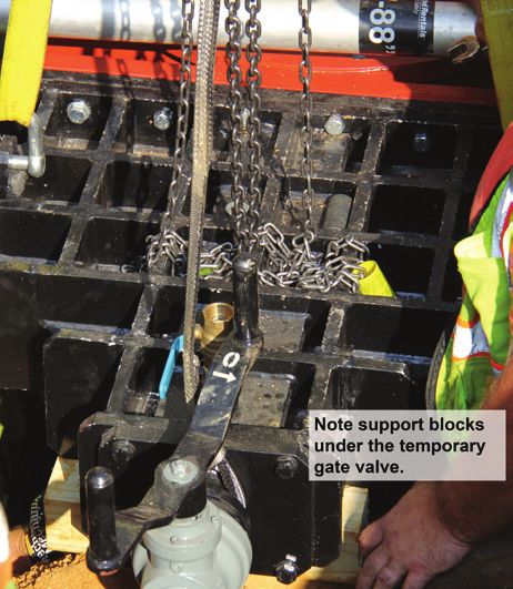
20”–24” Insta-Valve | Installation Instructions | 7

IMPORTANT: Never use air pressure. Instead use water                                                            comes into contact with the boring
pressure to prevent deformation and damage to the valve.                                                        bar to prevent the threads from
                                                                                                                being damaged.
2.5.8) Blow off pressure before removing the test flange.
                                                                                                                • Use the tightening tool to tighten
2.5.9) Remove the test flange.                                                                                    the pilot drill preventing the cutter
                                                                                                                  and the drill from disconnecting
2.5.10) Following the tightening pattern, re-torque mounting                                   Image 21           during boring.
bolts to recommended torque ONE additional time.
                                                                                                                • Retract the cutter assembly fully
2.6.0 Tapping Procedure                                                                                           after assembly to prevent damage
2.6.1 Assembly of Tapping Machine                                                                                 to the cutter during lifting and
                                                                                                                  placement on the adapter flange.
2.6.1) Assembly of the tapping equipment can be completed
before reaching the job site to save time at the job site.                                                      • Reset tapping counter to zero
                                                                                               Image 22           after the cutter assembly is fully
                                  2.6.2) Position the tap machine                                                 retracted.
                                  horizontally. Be sure to block and
                                  support the tapping machine near                        • Remove masking tape from pilot drill before proceeding
                                  the operating handles. Operate the                        with tap.
                                  handle to advance the boring bar
                                  forward until it is out of the tapping                                     2.6.8) Lift the tapping machine
                                  housing far enough to allow the                                            horizontally with three points of
                                  cutter to be mounted (see Image                                            contact. Attach straps to the tapping
                                  18).                                                                       machine lifting rings and a chain block
                                                                                                             connected to a hole on the housing
                                  2.6.3) Lift the cutter and engage the                                      flange (see Image 23).
                                  clutches between the cutter and the
                                  boring bar.                                                                2.6.9) Use a chain hoist to assist
          Image 18                                                                                           transitioning from horizontal to vertical.
                                  2.6.4) Slide the pilot drill through                                       Stand the tapping machine upright in a
                                  the cutter and clutch drive assembly.                                      vertical position on blocking and adjust
                                  Thread the pilot drill into the boring                                     lifting slings for a vertical lift. It is normal
                                  bar until it is hand tight against the                                     for the cutter assembly to protrude
                                  boring bar (see Image 19).                                                 from the tapping housing (see Image
                                                                                              Image 23
                                                                                                             24).
                                  2.6.5) Retract the boring bar back
                                  inside the tapping housing.                                                2.6.10) Mount the tapping machine on
                                                                                                             the valve body for the 24” valve or to
                                  2.6.6) Reset counter on tapping unit                                       the adapter flange for the 20” valve.
                                  to zero.
                                                                                                             2.6.11) Connect hydraulic power unit to
                                  2.6.7) Use masking tape to secure                                          the tapping machine.
          Image 19
                                  the coupon clips of the pilot drill
                                  (see Image 20).                                                            2.6.12) Connect the drain hose and
                                                                                                             the chip container to the drain part
                                  2.6.8) Place the pilot drill tightening                                    assembly on the valve body. Use the
                                  tool over the hexagon nut part of                                          union fitting to attach the drain hose
                                  the pilot drill, support the edge of                        Image 24       and chip container.
                                  the tap housing and use a 65 mm
                                  open-ended wrench at the edge of                    2.6.13) Open temporary gate valve and extend boring bar until
                                  the pilot drill tightening tool and                 pilot touches the top of pipe. You must continue to progress
          Image 20                tap the wrench several times with                   the boring bar/cutter based on the tapping depth (see Tapping
                                  a large hammer for tightening (see                  Depth Information on next page).
Images 21 and 22).
                                                                                      TAPPING DEPTH INFORMATION
IMPORTANT:
                                                                                      Tap until the counter reads 650 for 20- and 24-inch valves. You
    • Screw in the pilot drill by hand until the brim of the drill                    can continue to 700 on the counter if needed, but DO NOT PASS
                                                                                      700 on the counter.

© 2021 Hydra-Stop | All Rights Reserved. | Specifications subject to change without notice.
INSTA-VALVE 20-24 INSERTION VALVES - 20"-24" Installation Instructions - Revised March 2021 - Hydra-Stop
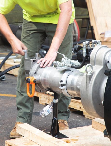
20”–24” Insta-Valve | Installation Instructions | 8
NOTE: Tapping Depth information is based on the Hydra-Stop                                               of the valve cartridge which are in
20”–24” tapping machine. Use of other tapping machines could                                             line with the shoulders of the valve
affect depth of tap.                                                                                     cartridge (see Image 26).

2.7.0 Performing the Tap                                                                                 2.8.4) Connect the valve suspender
2.7.1) Attach flushing hose and strainer to the flushing port ball                                       to the valve cartridge using the bolts
valves.                                                                                                  just removed. Tighten these bolts
                                                                                                         until finger tight and there is no gap
2.7.2) Open the ball valves on top of the tapping housing to                                  Image 26   between the bolts and the valve
allow air and fluid to escape from the tapping housing after the                                         suspender — an open-ended wrench
pilot drill penetrates the pipe.                                                                         can be lightly used if needed (see
                                                                                                         Image 27).
2.7.3) Open the drain assembly ball valve to assist in flushing of
chips as the tap is in process.                                                                          2.8.5) Place the empty insertion
                                                                                                         housing on support to provide
2.7.4) Engage the drive unit. Slowly turn the handle assembly in                                         clearance for the valve cartridge
a clockwise direction keeping slight, constant pressure until the                                        assembly which is taller than the
tap is complete.                                                                                         insertion housing (see Image 28).

CAUTION: Do not overfeed the tap. Overfeeding the tap could                                              NOTE: Approximately 8” of clearance
cause the cutter to jam.                                                                      Image 27   is required.

2.7.5) Close the ball valve on the tap housing as water fills the                                        2.8.6) Lift the inserting machine
housing and flows from the valve.                                                                        flange above and centered over the
                                                                                                         valve cartridge. Lower insertion flange
2.7.6) The tap is complete when the depth counter reaches the                                            until the valve suspender makes
desired depth.                                                                                           contact with the insertion flange (see
                                                                                                         Image 29).
2.7.7) Retract the cutter 2-3 turns before stopping the tapping                               Image 28
machine.                                                                                                 2.8.7) Thread the insertion flange
                                                                                                         gut rod into the valve suspender (see
2.7.8) Turn off the drive unit.                                                                          Image 30).

2.7.9) Retract the cutter assembly until the depth counter                                               2.8.8) Lift the insertion flange with
reaches zero / starting position.                                                                        the cartridge attached.

2.7.10) Close the temporary gate valve. Turn the handle                                       Image 29   2.8.9) Lift the valve cartridge and
counterclockwise to close.                                                                               insertion flange, then place them on
                                                                                                         the insertion housing. Make certain
2.7.11) Open the ball valve on the tapping machine housing to                                            the white line on the insertion flange
ensure the temporary gate valve is completely closed.                                                    is aligned with the white line on the
                                                                                                         insertion housing (see Image 31).
2.7.12) Remove the tapping machine assembly.
                                                                                                         2.8.10) Connect the insertion flange
2.7.13) Close flushing port ball valve.                                                                  to the insertion housing with the
                                                                                              Image 30   supplied bolts and nuts (16 M24 bolts,
2.7.14) Remove flushing strainer from hose. Leave hose
                                                                                                         nuts and washers).
attached for insertion equalization.
                                                                                                         CAUTION: Be sure to match the white
2.8.0 Assembly of Valve Cartridge, Insertion Machine,
and Insertion Housing                                                                                    lines on the valve cartridge with the
                                                                                                         white line on the insertion flange
2.8.1) Place the valve cartridge on supports.                                                            with the white line on the insertion
                                                                                                         housing to prevent the valve cartridge
                                   2.8.2) Lubricate the rubber ring                                      from being inserted improperly (see
                                   on the valve cartridge with the                            Image 31   Image 33 on next page).
                                   designated lubricant (see Image 25).

                                   2.8.3) Remove the 2 bolts of the
                                   valve stem cover on the upper side
          Image 25

© 2021 Hydra-Stop | All Rights Reserved. | Specifications subject to change without notice.
INSTA-VALVE 20-24 INSERTION VALVES - 20"-24" Installation Instructions - Revised March 2021 - Hydra-Stop
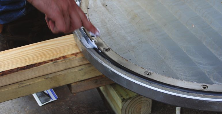
20”–24” Insta-Valve | Installation Instructions | 9
                              • Be sure to adjust the bolt holes of the                                                handle until the valve cartridge
                                insertion flange and the upper flange                                                  comes to a hard stop —
                                of the insertion housing to prevent                                                    approximately 1/2 to 1 turn.
                                the valve cartridge from being
                                inserted improperly.                                                                   2.10.8) Retrieve the set pin
                                                                                                                       cover plugs removed earlier.
                        • Never lift insertion assembly with
                          the insertion machine loops. Use                                                             NOTE: Number of set pins:
                          the hooks attached to the insertion                                   Image 37
Image 32        Image 33 flange.                                                                                       •   20” = 6 pins

2.9.0 Assembly of Inserting Tool                                                                                       •   24” = 8 pins
2.9.1) Lift the insertion housing and valve cartridge assembly                                                         2.10.9) Tape the threads of the
(see Image 32).                                                                                                        cover plugs with Teflon tape and
                                                                                                                       set aside.
2.9.2) Lower and place the insertion housing on the valve body
for the 24” valve or the adapter flange for a 20-inch valve.                                                           2.10.10) Using 17mm Allen
                                                                                                                       wrenches, two operators
                             2.9.3) Make sure the white line on the                                                    should simultaneously tighten
                             insertion housing is aligned with the                                                     the set pins in line with the
                             white line on the side of the valve body                                                  white paint mark on the valve
                             or adapter flange (see Image 34).                                  Image 38               and the set pin 180 degrees
                                                                                                                       opposite. Tightening in tandem
                            2.9.4) Connect the insertion housing to
       Image 34                                                                       will prevent over-tightening in any direction and will cause the
                           the valve body or adapter flange using the
                                                                                      bonnet to rotate to a centered position if the insertion is slightly
                           supplied bolts, nuts, and washers.
                                                                                      off center (see Image 38).
2.9.5) Connect the equalization hose to the equalization port of
                                                                                      2.10.12) Once the first set of opposing set pins have been
the insertion housing with the union coupling on the side of the
                                                                                      tightened into place, check for proper set pin depth using the
valve body.
                                                                                      Go / No-Go set pin gauge.
2.10.0 Inserting the Cartridge
                                                                                      NOTE: There are separate Go / No-Go gauges for the 20” and
2.10.1) Open the ball valves of the insertion housing and the                         24” valves.
ball valve on the side of the valve body.
                                                                                      2.10.13) Insert the GO side of the gauge into the set pin hole
2.10.2) Open the ball valve on the top of the insertion flange to                     and check that the shoulder of the gauge is touching the outside
release air as the insertion housing fills with water.                                face of the valve. If the shoulder does not reach the valve, then
                                                                                      the set pin has not been set deep enough. Continue to tighten
2.10.3) Rotate the handle for the temporary gate valve to fully                       the opposing set pins simultaneously until the shoulder on the
open.                                                                                 GO side of the gauge touches the valve (see Image 39).
CAUTION: Be sure to equalize pressure in the insertion housing
prior to opening the temporary gate valve to prevent damage to
the temporary gate valve.

                                  2.10.4) Set the insertion depth
                                  gauge in the area shown in images
                                  35 and 36.

                                  2.10.5) Using the insertion tool
                                  handle, turn the handle counter-
                                  clockwise to lower the cartridge.
         Image 35
                                  2.10.6) Continue to turn the handle                                             Image 39
                                  until the inserting rod lightly comes
                                  into contact with the depth gauge                   2.10.14) Once this GO depth has been confirmed, flip the gauge
                                  (see Image 37).                                     around and insert the NO-GO side into the set pin hole. Ensure
                                                                                      that the shoulder on this side DOES NOT touch the valve. If the
                                  2.10.7) Remove the gauge and                        shoulder does touch the valve, it means the set pin has been
                                  continue to turn the insertion                      inserted too far and must be withdrawn slightly.
          Image 36

© 2021 Hydra-Stop | All Rights Reserved. | Specifications subject to change without notice.
INSTA-VALVE 20-24 INSERTION VALVES - 20"-24" Installation Instructions - Revised March 2021 - Hydra-Stop
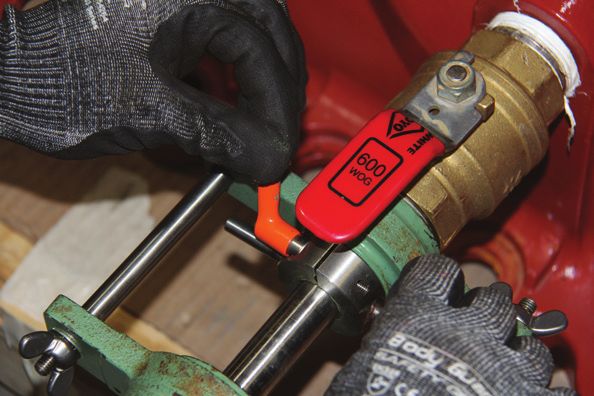
20”–24” Insta-Valve | Installation Instructions | 10
2.10.15) Once the first two set pins are in place, tighten the                                       2.13.0 Placing the Bonnet Flange
remaining set pins into place, tightening opposite set pins
                                                                                                     2.13.1) Lift, orient, and place the bonnet flange
simultaneously where possible. Perform the same GO / NO-GO
                                                                                                     on the upper side of the valve body and assemble
checks as were performed on the first pair of set pins.
                                                                                                     it with the special hexagon bolts and nuts M24
2.10.16) Rotate the inserting handle counterclockwise 1/2 to                                         nuts (see Image 42).
one turn to unload the inserting force loaded on the inserting
                                                                                                     2.13.2) Check the tightening torque of those
rod.
                                                                                                     hexagon bolts and nuts using a torque wrench.
2.10.17) Close the ball valve on the equalization port of the
                                                                                                     Tightening torque of hexagon bolts: 105 ft. lbs.
valve body to stop equalization.
                                                                                        Image 42
                                                                                                     2.14.0 Removing the Temporary Gate Valve
2.10.18) Slowly open the ball valve on the insertion flange by
small amounts and blow off any pressure.                                              2.14.1) Attach lifting straps with three points of contact to the
                                                                                      temporary gate valve and apply slight lifting pressure.
IMPORTANT
                                                                                      2.14.2) Loosen and remove the nuts and bolts securing the
  • Never release equalization pressure before the valve                              temporary gate valve from the valve body.
    cartridge has been secured with the set pins.
                                                                                      2.14.3) Remove the temporary gate valve from the valve body.
  • Be sure to insert all set pins to the designated depth
    and make them as even as possible to prevent the valve                            2.15.0 Assembly of Side Lid and Operating Nut
    cartridge from becoming misaligned.                                                                                 2.15.1) Place the temporary
                                                                                                                        gate valve cover over the
2.11.0 Removal of Inserting Tool                                                                                        temporary gate valve port.
                                    2.11.1) Use an adjustable wrench                                                    Secure the cover with the 4
                                    to turn the gut rod several                                                         M16 nuts, bolts, and washers
                                    turns counterclockwise until                                                        removed earlier (see Image
                                    it disengages from the valve                                                        43).
                                    suspender (see Image 40).
                                                                                                 Image 43               2.15.2) Check the tightening
                                    2.11.2) Disengagement is achieved                                                   torque of those hexagon
          Image 40                  when the gut rod can move freely                                                    bolts and nuts using a torque
                                    up and down.                                                                        wrench.

                                    2.11.3) Rotate the insertion handle               NOTE: Tightening torque of hexagon bolts: 45 ft. lbs.
                                    clockwise to retract the insertion
                                    rod completely.                                   2.15.3) Re-install the two bolts in the valve stem cover.

                                    2.11.4) Remove the equalization                   2.15.4) Set the operating nut on the valve stem and secure with
                                    hose from the insertion housing                   the M16 bolt.
                                    and the valve body (see Image 41).
                                                                                      2.15.5) Insert and tighten the set pin cover plugs.
                                    2.11.5) Open the insertion housing
          Image 41                                                                    2.16.0 Removal of Valve Body Ball Valve
                                    ball valve and drain water from the
                                    insertion housing.                                                            2.16.1) Fully close the ball valve on
                                                                                                                  the side of the valve body.
2.12.0 Removal of Insertion Housing
2.12.1) Loosen and remove the nuts and bolts securing the                                                         2.16.2) Remove the nipple, elbow,
insertion housing to the valve body or the adapter flange.                                                        and the female union joint assembly
                                                                                                                  (see Image 44).
2.12.2) Using lifting straps, remove the insertion housing.
                                                                                              Image 44            2.16.3) Attach the completion plug
2.12.3) Remove the valve suspender from the valve cartridge.                                                      removed from the valve body in
                                                                                                                  section 2.4 Hydrostatic Test, Step 1
2.12.4) Remove the adapter flange if installing a 20-inch valve.                                                  to the bottom edge of the inserting
                                                                                                                  rod of the special ball valve removal
                                                                                                                  tool.

© 2021 Hydra-Stop | All Rights Reserved. | Specifications subject to change without notice.
20”–24” Insta-Valve | Installation Instructions | 11
See Appendix B for complete seal plug tool setup and usage
instructions.

2.16.4) Remove the ball valve and the short nipple.

2.16.5) Apply sealing tape to the outer cover plug threads.

2.16.6) Thread the outer cover plug into the valve body.

2.16.7) Tighten the outer cover plug with an adjustable wrench.

2.16.8) Fully disassemble, clean and store equipment.

2.16.9) Temporary Gate Valve Maintenance: Wipe down
temporary gate valve seals after each use by extending the gate
valve out of the gate valve housing. Remove grease, chips, etc.

IMPORTANT: Support the gate valve plate when extending out
of the gate housing to protect the gate valve feed screw.

2.16.10) Order replacement parts, if necessary, to replace lost,
damaged, or worn components.

Congratulations. Your Insta-Valve 20–24 is installed.

2.18.0 Operating Turns
Operating Turns are below. Numbers may vary +/-3 turns.

20” valve: 72–74 turns

24” valve: 78–80 turns

© 2021 Hydra-Stop | All Rights Reserved. | Specifications subject to change without notice.
INSTA-VALVE 20-24 INSERTION VALVES
Appendices
20”–24” Insta-Valve | Installation Instructions | 13
Appendix A — 20” and 24” Valve Mounting Blot Torque Patterns

                       20”valve
            bolt torque tightening pattern

                                                                                                        24” valve
                                                                                              bolt torque tightening pattern

© 2021 Hydra-Stop | All Rights Reserved. | Specifications subject to change without notice.
20”–24” Insta-Valve | Installation Instructions | 14
Appendix B — 20” Valve Excavation and Concrete Support Details

                                            Minimum excavation dimension: 6’ wide x 9’ long
                                          Recommended excavation dimension: 8’ wide x 9’ long

© 2021 Hydra-Stop | All Rights Reserved. | Specifications subject to change without notice.
20”–24” Insta-Valve | Installation Instructions | 15
Appendix C — 24” Valve Excavation and Concrete Support Details

                                            Minimum excavation dimension: 6’ wide x 9’ long
                                          Recommended excavation dimension: 8’ wide x 9’ long

© 2021 Hydra-Stop | All Rights Reserved. | Specifications subject to change without notice.
20”–24” Insta-Valve | Installation Instructions | 16
Appendix D — Seal Plug Remove and Replacement Using the Seal Plug Tool

                                             D.1) Remove the seal plug                                              seal plug by turning the
                                             NPT cover (see Image 46).                                              inserting rod assembly,
                                             D.2) Thread the seal plug                                              using the handles,
                                             removal tool into the side                                             counterclockwise.
                                             port opening — wing                                                    D.13) Once unthreaded,
                                             nuts on the tool may                                                   draw the inserting rod
                                             contact the valve body.                                                backwards, loosening and
               Image 46                      For seal plug removal, it                         Image 52             tightening the locking
                                             is acceptable if the tool is                                           clamp lever until the rod is
                                             not fully tightened in the                                             drawn back to a hard stop
                                             side port opening threads                                              (see Image 52).
                                             (see Image 47).                                                        D.14) Unthread the plug
                                             D.3) Unthread the rear                                                 insertion tool from the
                                             cylinder cover from                                                    valve body (see Image 53).
                                             the seal plug tool. This                                               D.15) Retain the plug
               Image 47
                                             exposes the fixing nuts                                                insertion tool and sealing
                                             and the gut rod (see                              Image 53
                                                                                                                    plug in a safe place until
                                             Image 48).                                                             used for final completion.
                                             D.4) Loosen the handle                  D.16) Perform the tap and the insertion of the valve
                                             of the inserting rod stop               cartridge.
                                             collar (see Image 49).
                                                                                     Seal Plug Replacement and Side Port Ball Valve Removal
                                             D.5) Slide the stop collar
               Image 48                      fully backwards.                                                       D.17) Remove the drain
                                                                                                                    parts except for the side
                                             D.6) Tighten the locking                                               port ball valve and the
                                             lever handle.                                                          short nipple.
                                             D.7) Slide inserting rod                                               D.18) Thread the rear
                                             assembly forward (see                                                  cylinder cover onto the
                                             Image 50).                                                             seal plug tool (see Image
                                             D.8) Repeat steps 4–7                             Image 54             54).
               Image 49                      until inserting rod                                                    D.19) Thread the seal plug
                                             contacts the seal plug.                                                tool into the side port ball
                                             D.9) Slightly twist the                                                valve.
                                             inserting rod so the                                                   D.20) Slowly open the
                                             square of the inserting                                                small air vent ball valve
                                             rod head engages the                                                   on the rear cylinder (see
                                             square of the seal plug.                                               Image 55).
                                                                                               Image 55
                                             D.10) Thread the gut rod                                                D.21) Fully open the side
               Image 50
                                             into seal plug by turning                                              port ball valve. Bleed off
                                             the locked fixing nut (see                                             any air through the rear
                                             Image 51).                                                             cylinder cover ball valve
                                             D.11) Tighten the locking                                              and allow the seal plug tool
                                             lever handle.                                                          to fill with water (see Image
                                             D.12) Remove the                                                       56).
                                                                                               Image 56
               Image 51
© 2021 Hydra-Stop | All Rights Reserved. | Specifications subject to change without notice.
20”–24” Insta-Valve | Installation Instructions | 17
Appendix D — Seal Plug Remove and Replacement Using the Seal Plug Tool

D.22) Close the rear cylinder ball valve.                                             D.34) Tighten the locking lever handle.
D.23) Loosen the handle of the inserting rod stop collar.                             D.35) Slide inserting rod assembly fully backwards.
D.24) Slide the stop collar fully backwards.                                          D.36) Repeat steps 33–35 until the inserting rod is fully
D.25) Tighten the locking lever handle.                                               retracted.

D.26) Slide inserting rod assembly forward.                                           D.37) Close the seal port ball valve.

                                             D.27) Repeat steps 7–10                  D.38) Unthread the seal plug tool from the ball valve.
                                             until seal plug makes                                                    D.39) Re-check for leaks
                                             contact with the inner                                                   and remove the side port
                                             threads of the side port.                                                ball valve and nipple.
                                             D.28) After the seal                                                     D.40) Wrap seal tape on
                                             plug contacts the inner                                                  seal plug cover. Thread and
                                             threads, turn the inserting                                              tighten the seal plug cover
               Image 57
                                             rod assembly clockwise                              Image 61             into the valve body (see
                                             using the handles (see                                                   Image 61).
                                             Image 57).
                                             D.29) After the seal plug
                                             is tightened, fully open
                                             the air vent valve and
                                             check whether there is
               Image 58                      fluid leaking from the air
                                             vent valve. If no liquid is
                                             leaking continue to step
                                             30.
                                             D.30) Remove the rear
                                             outside cylinder (see
                                             Image 58).
                                             D.31) Loosen the gut rod
               Image 59                      by turning the fixing nut
                                             counterclockwise and
                                             remove the gut rod from
                                             the seal plug (see Image
                                             59).
                                             D.32) Loosen the handle
                                             of the inserting rod stop
                                             collar.
               Image 60                      D.33) Slide the stop collar
                                             fully forwards (see Image
60).

© 2021 Hydra-Stop | All Rights Reserved. | Specifications subject to change without notice.
20”–24” Insta-Valve | Installation Instructions | 18
Appendix E — Product Cut Sheet — Insta-Valve 20-24

                                                                                              Item       Name                   Material                Qty.
                                                                                              1          Operating Nut          Steel, Cast             1
                                                                                              2          Bonnet Cover           Stainless Steel 4
                                                                                                         Bolts
                                                                                              3          Bonnet Cover           Ductile Iron            1
                                                                                              4          Seal Ring              SBR Rubber              1
                                                                                              5          Feed Screw             Stainless Steel 1
                                                                                              6          Valve Cartridge        Various                 1
                                                                                                         Assembly
                                                                                              7          Bonnet Flange          Ductile Iron            1
                                                                                              8          Resilient Wedge        SBR Rubber              1
                                                                                              9          Set Pin Cover          Steel, S25C             20” valve - 6
                                                                                                         Plug                                           24” valve - 8
                                                                                              10         Set Pin                Stainless Steel 20” valve - 6
                                                                                                                                                24” valve - 8
                                                                                              11         Seal Plug Cover        Stainless Steel 1
                                                                                              12         Seal Plug              Stainless Steel 1
                                                                                              13         Valve Mounting         Stainless Steel 20” valve:
                                                                                                         Hardware (Bolts,                       Bolts - 18
                                                                                                         Nuts, Washers)                         Nuts - 18
                                                                                                                                                Washers - 36

                                                                                                                                                        24” valve:
                                                                                                                                                        Bolts - 22
                                                                                                                                                        Nuts - 22
                                                                                                                                                        Washers - 44
                                                                                              14         Bonnet Flange          Stainless Steel Bolts - 16
                                                                                                         Hardware                               Nuts - 16
                                                                                                                                                Washers - 32
                                                                                              15         Gate Valve Cover Ductile Iron                  1
                                                                                              16         Gate Valve Cover Stainless Steel 4
                                                                                                         Bolts
                                                                                              17         Upper Valve            Ductile Iron            1
                                                                                                         Body
                                                                                              18         Lower Valve            Ductile Iron            1
                                                                                                         Body

                                                   Dimensions                                                         Other Specifications

                                                   Size   A       B          C         D           Approx.            Valve Body Minimum Test Pressure: 1.5 times system working
                                                                                                   Weight             pressure

                                                   20”    35.5”   52.5”      32.5”     42”         2,228 lbs          Valve Body Maximum Test Pressure: 225 psi, Maximum Working
                                                                                                                      Pressure: 150 psi
                                                   24     39.5”   60.5”      36”       47”         3.139 lbs
                                                                                                                      Coatings: Inside - .3 mm epoxy-powder coating. Outside - .25 mm
                                                                                                                      epoxy powder coating

  Proprietary Information: This property of Hydra-Stop shall not be used, reproduced or distributed without written consent. All design and invention rights are re-
  served. Materials, pricing and specifications subject to change without notice.

© 2021 Hydra-Stop | All Rights Reserved. | Specifications subject to change without notice.
20”–24” Insta-Valve | Installation Instructions | 19
Appendix F — Installation Equipment
   Equipment Image                                                                   Name

                                                                                              Temporary Gate Valve

                                                                                                Tapping Machine

                                                                                               Insertion Machine

                                                                                                  Test Flange

                                                                                                Valve Suspenders

© 2021 Hydra-Stop | All Rights Reserved. | Specifications subject to change without notice.
20”–24” Insta-Valve | Installation Instructions | 20
Appendix F — Installation Equipment

   Equipment Image                                                                   Name

                                                                                                  Insertion Housing

                                                                                              20” to 24” Adapter Flange

                                                                                                   Seal Plug Tool

© 2021 Hydra-Stop | All Rights Reserved. | Specifications subject to change without notice.
20”–24” Insta-Valve | Installation Instructions | 21
Appendix G — Standard Tools

     No.                               Name                                                   Size and spec etc.
       1           Rachet wrench                                         24, 30, 36 mm
       2           Open Ended Wrench                                     24, 36, 65 mm
       3           Adjustable wrench                                     Total length: 300 mm, Max. opening 34 mm
       4           Pipe wrench                                           Total length: 300 mm, Max. diameter 70 mm
       5           Rachet handle                                         Total length: 270 mm
       6           Long hexagon Allen Wrench                             17 mm
       7           Hexagon Allen Wrench                                  19,22 mm
       8           Torque wrench                                         Max. 300 ft. lbs.

       9           Hexagonal socket (deep)                               36 mm Depth: 100 mm

      10           Mini lever hoist                                      Max. load: 550 lbs., Chain length: 6.5 feet

      11           Hammer                                                Dead blow type

(Unit: mm)

© 2021 Hydra-Stop | All Rights Reserved. | Specifications subject to change without notice.
20”–24” Insta-Valve | Installation Instructions | 22
Appendix H — Side Tapping and Horizontal Bevel Gear Use

H.1) Preperation for Installation                                                                                                H.2.8) Remove the set
                                                                                                                                 pin cover plugs.
H.1.1) Check and inspect the installation location.
                                                                                                                                 H.2.9) Wrap Teflon
H.1.2) Thoroughly clean the pipe surface with a wire brush
                                                                                                                                 seal tape on the set
where the valve body will be installed to ensure all loose debris
                                                                                                                                 pin cover plugs and
and material is removed.
                                                                                                                                 re-install into the valve
H.1.3) Utilizing safe lifting procedures and equipment, place                                                                    body.
the valve body and valve sleeve into position to be mounted
                                                                                                                               H.2.10) Use pipe
horizontally.
                                                                                                                               restraints on either
                                                                                                     Image H3
H.2) Assembly of Valve Body                                                                                                    side of the valve body
                                                                                                                               to provide additional
H.2.1) Before lifting and rotating the valve body into the                           support (in place of concrete due to orientation of the valve) —
installation position, lubricate the surface of the rubber throat                    restraints not provided.
gasket at around the valve opening.
                                                                                     H.3 Assembly of Temporary Gate Valve
                                 H.2.2) Rotate the valve body into
                                 mounting position (see Image H1).                   H.3.1) Open the temporary gate valve. Be sure to block under
                                                                                     and support the gate (see Image H4).
                                 • Drain assembly ball valve must be
                                   facing towards the ground at this
                                   position (see Image H2).

                                 • Rig the body and sleeve to mount
                                   horizontally.

                                 H.2.3) Install mounting bolts to attach
                                 the sleeve to the valve body and
                                 finger tighten the nuts and bolts.
                                                                                                                  Image H4
                                 H.2.4) Put a level on the upper valve
                                 body and tighten the bolts and nuts.                H.3.2) Lubricate the temporary gate valve gasket and the O-ring
         Image H1                Use blocking to support the valve                   on the rectangular face of the temporary gate valve flange.
                                 body before fully tightening hardware.
                                                                                     H.3.3) Lift the temporary gate valve utilizing a chain fall to
                                            NOTE: Use a base plate to                account for weight imbalances.
                                            keep blocking from sinking
                                            on weak or saturated ground                 • Orient the gate valve to match up to the rectangular flange
                                            (see Image H3).                               on the valve body.

                                            H.2.5) Using a torque                    H.3.4) Remove the nuts and bolts holding the temporary gate
                                            wrench, tighten nuts in                  valve cover in place on the valve body. Remove the temporary
                                            proper pattern. Repeat                   gate valve cover. Keep the bolts and nuts in a safe location.
                                            tightening pattern in
                                            no more than 25 ft.                      H.3.5) Lift and move the temporary gate vale towards the
                                            lb. increments until                     temporary gate valve attachment port of the valve body. Level
                                            recommended torque is                    the temporary valve with the chain fall.
               Image H2                     reached.
                                                                                     H.3.6) Mount the temporary gate valve to the rectangle flange of
H.2.6) Wait 10 minutes to allow the gasket to fully seat then                        the valve body using the bolts and adjust the circular portion of
re-tighten bolts to recommended torque three addition times,                         the gate valve into the gate valve slot on the valve body until the
following the tightening pattern.                                                    flanges come into contact with each other.

H.2.7) Check and re-adjust the support blocks or jacks under the                     H.3.7) Block and support below the temporary gate valve after
valve body to be sure they are supporting the valve.                                 installing the nuts and bolts and before removing the lifting
                                                                                     devices.

© 2021 Hydra-Stop | All Rights Reserved. | Specifications subject to change without notice.
20”–24” Insta-Valve | Installation Instructions | 23
Appendix H — Side Tapping and Horizontal Bevel Gear Use
H.4) Hydrostatic Test                                                                H.5.6) Retract the boring bar back inside the tapping housing
                                                                                     and reset the counter to zero.
H.4.1) Remove the seal plug NPT cover plug and place in a safe
location for later use.                                                              NOTE: Counter may not reach zero due to the sweeping
                                                                                     attachments. Counter should not read above 10.
                                                       H.4.2) Assemble the
                                                       drain parts.                  H.5.7) Use masking tape to secure the coupon clips of the pilot
                                                                                     drill.
                                                       H.4.3) Place the
                                                       O-ring on the valve           H.5.8) Place the pilot drill tightening tool over the hexagon nut
                                                       body using a food             of the pilot drill and use to tighten.
                                                       grade lubricant to
                                                       hold in place (see            H.5.9) On the valve body, use tape to cover the bottom set pin
                                                       Image H5).                    holes (see Image H7).
                                                       H.4.4) Using a lift,
                     Image H5                          place the test flange
                                                       on the valve.

H.4.5) Remove the top middle set pin on the valve body.

H.4.6) Fill the valve body with water and use the set pin hole to
purge all air. Once the valve is full, place the set pin back into the
valve body.

H.4.7) Connect a pressure gauge and pressure test pump to the                                                     Image H7
test lid and begin pressure test procedure.

H.4.8) Blow off pressure before removing the test flange.                            H.5.10) Lift the tapping machine horizontally with three points of
                                                                                     contact. Attach straps to the tapping machine lifting rings and a
H.4.9) Remove the test flange.                                                       chain block connected to a hole on the housing flange.

H.4.10) Following the tightening pattern, re-torque the mounting                     H.5.11) Ensure that the O-ring is still in place on the valve body.
bolts to recommended torque one additional time.
                                                                                     H.5.12) Mount the tapping machine on the valve body in the
H.5) Assembly of Tapping Machine                                                     horizontal position.
H.5.1) Assembly of the tapping equipment can be completed                            H.5.13) Block and support the machine near the operating
before reaching the job site to save time.                                           handle (see Image H8).
                                      H.5.2) Assemble sweeping
                                      attachments to the cutter with
                                      provided hardware and wrench
                                      tighten (see Image H6).

                                      H.5.3) Position the tap machine
                                      horizontally. Be sure to block and
                                      support the machine near the
                                      operating handles. Operate the
                                      handle to advance the boring
                                      bar forward until it is out of the
                                                                                                                  Image H8
            Image H6                  tapping housing far enough to
                                      allow the cutter to be mounted.
                                                                                     H.5.14) Connect the hydraulic power unit to the machine.
H.5.4) Lift the cutter and engage the clutches between the cutter
                                                                                     H.5.15) Connect the drain hose and chip container to the drain
and boring bar.
                                                                                     part assembly on the valve body.
H.5.5) Slide the pilot drill through the cutter and clutch drive
                                                                                     H.5.16) Ensure that the temporary gate valve is completely open
assembly. Thread the pilot drill into the boring bar until it is hand
                                                                                     and extend boring bar until pilot touches the top of the pipe.
tight.

© 2021 Hydra-Stop | All Rights Reserved. | Specifications subject to change without notice.
20”–24” Insta-Valve | Installation Instructions | 24
Appendix H — Side Tapping and Horizontal Bevel Gear Use
H.6) Performing the Tap                                                              scooter should be on the side of the cartridge that will be in line
                                                                                     with the drain valve on the valve body. The 20” and 24” have
H.6.1) Attach flushing hose and strainer to the flushing port ball
                                                                                     separate scooters, be sure to use the correct one (see Image
valves.
                                                                                     H10).
H.6.2) Open the ball valves on top of the tapping housing to
                                                                                     H.7.6) Place the empty insertion housing on support to provide
allow air and fluid to escape from the tapping housing after the
                                                                                     clearance for the valve cartridge assembly which is taller than
pilot drill penetrates the pipe.
                                                                                     the insertion housing.
H.6.3) Open the drain assembly ball valve to assist in flushing of
                                                                                     H.7.7) Lift the insertion machine flange above and centered
chips as the tap is in process.
                                                                                     over the valve cartridge. Lower insertion flange until the valve
IMPORTANT: Failure to flush chips can prevent the cartridge                          suspender contacts the insertion flange.
from sealing when inserted.
                                                                                     H.7.8) Thread the insertion flange gut rod into the valve
H.6.4) Engage the drive unit. Slowly turn the handle assembly in                     suspender and lift the insertion flange with the cartridge
a clockwise direction keeping slight, constant pressure until the                    attached.
tap is complete.
                                                                                     H.7.9) Lift the valve cartridge and insertion flange and place
H.6.5) Close the ball valve on the tap housing as water fills the                    them on the insertion housing. Make certain the white line
housing and flows from the valve.                                                    on the insertion flange is aligned with the white line on the
                                                                                     insertion housing.
H.6.6) The tap is complete when the depth counter reaches the
desired depth. Tap until the counter reaches 650. DO NOT tap                         H.8) Assembly of Inserting Tool
past 700.                                                                            H.8.1) Lift the insertion housing using two points of contact and
                                                                                     utilizing a chain fall. Slowly position until it is horizontal.
H.6.7) Retract the cutter until the counter reads 450 before
stopping the tapping machine.                                                        NOTE: Ensure that the correct side of the insertion housing is
                                                                                     facing down so that the line on the housing and the line on the
H.6.8) Turn off the drive unit.                                                      valve body match up.
H.6.9) Retract the cutter assembly until the depth counter                           When the insertion housing is horizontal, the valve scooter
reaches zero or its original position.                                               should be on the bottom supporting the cartridge.
H.6.10) Close the temporary gate valve.                                              H.8.2) Place the insertion housing on the valve body and ensure
                                                                                     the white lines are aligned. Block the insertion housing (see
H.6.11) Close the flushing port ball valve.                                          Image H11).
H.7) Assembly of Valve Cartridge, Insertion Machine, and
Insertion Housing
                                H.7.1) Place the valve cartridge on
                                supports.

                                H.7.2) Lubricate the rubber ring on the
                                valve cartridge with the designated
                                lubricant (see Image H9).

         Image H9               H.7.3) Remove the 2 bolts of the valve                                           Image H11
                                stem cover on the upper side of the
                                valve cartridge, which are in line with              H.8.3) Connect the insertion housing with the supplied bolts,
                                the shoulders of the valve cartridge.                nuts, and washers.
                                H.7.4) Connect the valve suspender                   H.8.4) Connect the equalization hose to the equalization port of
                                to the valve cartridge using the bolts               the insertion housing with the union coupling on the side of the
                                just removed. Tighten these bolts until              valve body.
                                finger tight so there is no gap between
                                the bolts and valve suspender.                       H.9) Inserting the Cartridge
                                H.7.5) Connect the valve insertion                   H.9.1) Follow the steps in Section 2.10.0 on page 9.
                                scooter to the cartridge gusset. The
          Image H10
© 2021 Hydra-Stop | All Rights Reserved. | Specifications subject to change without notice.
20”–24” Insta-Valve | Installation Instructions | 25
Appendix H — Side Tapping and Horizontal Bevel Gear Use
H.10) Removal of Inserting Tool                                                      H.13) Operating Turns
H.10.1) Follow the steps in Section 2.11.0 on page 10.                               H.13.1) Operating turns are below.

H.11) Removal of Insertion Housing                                                      • 20” valve: 216–222 turns
H.11.1) Loosen and remove the nuts and bolts securing the
                                                                                        • 24” valve: 234–240 turns
insertion housing to the valve body or the adapter flange.
                                                                                     H.14) Trench Dimensions
H.11.2) Using the same lifting method as before, slide the
insertion housing away from the valve body until it has cleared                      H.14.1) Recommended Trench Dimensions: 10 ft. wide x 20 ft.
the cartridge before lifting.                                                        long

H.11.3) Remove the valve suspender from the valve cartridge.                         H.15) Minimum Required Depth
                                                                                        • 12” below pipe everywhere
H.11.4) Remove the valve scooter from the valve cartridge.
                                                                                        • 24” below pipe for drain valve assembly
H.11.5) Block the valve cartridge.

H.12) Installing the Bevel Gear Assembly
H.12.1) Remove the remaining two bolts from the valve stem
cover.

H.12.2) Place the feed screw to bevel gear adaptor over the feed
screw.

H.12.3) Line up the bolt holes on the bevel gear mounting plate
so that the operating nut on the gearbox is facing up.

H.12.4) Turn the operating nut to match the inner drive bushing
geometry with the adaptor piece’s position and slide the
assembly over the adaptor.

NOTE: The mounting plate should be flush to the valve stem
cover.

H.12.5) Use the bolts and provided lock washers to secure the
bevel gear to the valve stem cover. Tighten and ensure that the
bevel gear assembly is secure (see Image H12).

                                  Image H12

H.12.6) Add valve box adaptor over the gearbox (valve box not
provided).

© 2021 Hydra-Stop | All Rights Reserved. | Specifications subject to change without notice.
You can also read