Installation and operating instructions - Hot water heat pump (indoor unit) - EKHHP300A*2V3 EKHHP500A*2V3 - Daikin
←
→
Page content transcription
If your browser does not render page correctly, please read the page content below
Installation and operating
                           instructions

                          Hot water heat pump
                                  (indoor unit)

                          Installation and operating instructions
                                           Hot water heat pump      English
                                                    (indoor unit)

EKHHP300A*2V3
EKHHP500A*2V3
List of contents
1      Particular instructions for safe operation . 3                                             7.3     Operating modes. . . . . . . . . . . . . . . . . . . . . . . 24
 1.1       Particular safety instructions . . . . . . . . . . . . . . . 3                            7.3.1   ECO. . . . . . . . . . . . . . . . . . . . . . . . . . . . . . . . . . .   24
 1.2       Observing instructions . . . . . . . . . . . . . . . . . . . . 3                          7.3.2   AUTOMATIC . . . . . . . . . . . . . . . . . . . . . . . . . . . .          24
                                                                                                     7.3.3   Low Noise . . . . . . . . . . . . . . . . . . . . . . . . . . . . . .      24
                                                                                                     7.3.4   High Output . . . . . . . . . . . . . . . . . . . . . . . . . . . .        24
2      Safety . . . . . . . . . . . . . . . . . . . . . . . . . . . . . . 4                       7.4     Setting the timer programme. . . . . . . . . . . . . . 24
 2.1       Warning signs and explanation of symbols . . . . 4                                        7.4.1   Display switching times . . . . . . . . . . . . . . . . . . . . 25
    2.1.1       Meaning of the warnings . . . . . . . . . . . . . . . . . . . . .4                   7.4.2   Programming switching times . . . . . . . . . . . . . . . 25
    2.1.2       Validity. . . . . . . . . . . . . . . . . . . . . . . . . . . . . . . . . . .4       7.4.3   Delete switching time . . . . . . . . . . . . . . . . . . . . . 25
    2.1.3       Handling instructions. . . . . . . . . . . . . . . . . . . . . . . .4
                                                                                                  7.5     Parameter settings . . . . . . . . . . . . . . . . . . . . . 26
 2.2       Avoid danger . . . . . . . . . . . . . . . . . . . . . . . . . . . 4                      7.5.1   Setting parameters . . . . . . . . . . . . . . . . . . . . . . .           26
 2.3       Intended use . . . . . . . . . . . . . . . . . . . . . . . . . . . 4                      7.5.2   Parameter description . . . . . . . . . . . . . . . . . . . . .            27
 2.4       Instructions for operating safety . . . . . . . . . . . . . 5                             7.5.3   Parameter factory settings. . . . . . . . . . . . . . . . . .              29
    2.4.1       Before working on the hydraulic system . . . . . . . . .5                            7.5.4   Individual parameter settings. . . . . . . . . . . . . . . .               30
    2.4.2       Electrical installation . . . . . . . . . . . . . . . . . . . . . . . .5             7.5.5   Individual switching time settings . . . . . . . . . . . .                 30
    2.4.3       Working on cooling systems (heat pump) . . . . . . . .5
    2.4.4       Site of installation . . . . . . . . . . . . . . . . . . . . . . . . . .5
                                                                                                 8      Malfunctions and fault codes . . . . . . . . . . 31
    2.4.5       Sanitary connection. . . . . . . . . . . . . . . . . . . . . . . . .6
    2.4.6       Requirements for the depressurised storage tank                                   8.1     Failures . . . . . . . . . . . . . . . . . . . . . . . . . . . . . . 31
                water . . . . . . . . . . . . . . . . . . . . . . . . . . . . . . . . . . . .6    8.2     Fault code . . . . . . . . . . . . . . . . . . . . . . . . . . . . 33
    2.4.7       Operation . . . . . . . . . . . . . . . . . . . . . . . . . . . . . . . .6
    2.4.8       Instructing the user/owner. . . . . . . . . . . . . . . . . . . .6               9      Service and maintenance . . . . . . . . . . . . . 34
                                                                                                  9.1     General . . . . . . . . . . . . . . . . . . . . . . . . . . . . . . 34
3      Product description. . . . . . . . . . . . . . . . . . . 7                                 9.2     Periodic Checks . . . . . . . . . . . . . . . . . . . . . . . 34
                                                                                                     9.2.1   Filling, topping up storage tank - without installed
4      Set-up and installation . . . . . . . . . . . . . . . . 9                                             solar system . . . . . . . . . . . . . . . . . . . . . . . . . . . . 35
                                                                                                     9.2.2   Filling, topping up storage tank - with optional
 4.1       Tightening torque . . . . . . . . . . . . . . . . . . . . . . . 9
                                                                                                             KFE filling connection or with installed DrainBack
 4.2       Scope of delivery . . . . . . . . . . . . . . . . . . . . . . . . 9                               solar system DrainBack . . . . . . . . . . . . . . . . . . . 35
 4.3       Set-up . . . . . . . . . . . . . . . . . . . . . . . . . . . . . . . 10
 4.4       Hydraulic connection . . . . . . . . . . . . . . . . . . . . 11
                                                                                                 10 Technical data . . . . . . . . . . . . . . . . . . . . . . 36
    4.4.1       Optional: Connection of an external heat
                generator. . . . . . . . . . . . . . . . . . . . . . . . . . . . . . . .12        10.1 Information on the type plate. . . . . . . . . . . . . . 37
 4.5       Laying coolant lines . . . . . . . . . . . . . . . . . . . . . 13
 4.6       Pressure test and filling the coolant circuit. . . . 13                               11 Notes. . . . . . . . . . . . . . . . . . . . . . . . . . . . . . 38
 4.7       Filling the system with water . . . . . . . . . . . . . . 14
    4.7.1       Filling the hot water heat exchanger . . . . . . . . . . .14                     12 List of keywords . . . . . . . . . . . . . . . . . . . . 39
    4.7.2       Filling the storage tank . . . . . . . . . . . . . . . . . . . . .14
 4.8       Electrical connection . . . . . . . . . . . . . . . . . . . . 14
    4.8.1       Connection EKHHP on heat pump external unit,
                mains connection Booster-Heater (BSH) . . . . . . .15
    4.8.2       High/low tariff mains connection (HT/NT) . . . . . . .16
    4.8.3       Connection EVU receiver (intelligent regulator
                Smart Grid - SG) . . . . . . . . . . . . . . . . . . . . . . . . . .16
    4.8.4       Optional: Connection of an external heat
                generator. . . . . . . . . . . . . . . . . . . . . . . . . . . . . . . .16

5      Start-up . . . . . . . . . . . . . . . . . . . . . . . . . . . . 17
 5.1       Start-up . . . . . . . . . . . . . . . . . . . . . . . . . . . . . . 17
    5.1.1       Requirements:. . . . . . . . . . . . . . . . . . . . . . . . . . . .17
    5.1.2       Start the system . . . . . . . . . . . . . . . . . . . . . . . . . .17

6      Decommissioning . . . . . . . . . . . . . . . . . . . 19
 6.1       Temporary shutdown . . . . . . . . . . . . . . . . . . . . 19
    6.1.1       Draining the storage tank . . . . . . . . . . . . . . . . . . .19
    6.1.2       Draining the hot water circuit. . . . . . . . . . . . . . . . .20
 6.2       Final shutdown . . . . . . . . . . . . . . . . . . . . . . . . . 20

7      Operation, Parameters . . . . . . . . . . . . . . . 22
 7.1       Displays and function of the operating
           elements . . . . . . . . . . . . . . . . . . . . . . . . . . . . . 22
 7.2       Basic functions . . . . . . . . . . . . . . . . . . . . . . . . . 23
    7.2.1       Switching the system on and off . . . . . . . . . . . . . .23
    7.2.2       Setting the clock . . . . . . . . . . . . . . . . . . . . . . . . . .23
    7.2.3       Display of the current Temperature. . . . . . . . . . . .23
    7.2.4       Defrost . . . . . . . . . . . . . . . . . . . . . . . . . . . . . . . . .23

Installation and operating instructions                                                                                                                                    DAIKIN EKHHP
                                                                                                                                                               DAIKIN Hot water heat pump
2                                                                                                                                                          008.1423499_08 – 06/2020 – EN
1 x Particular instructions for safe operation
1 Particular instructions for safe operation
1.1 Particular safety instructions
WARNING!
Disregarding the following safety instructions may result in serious physical injury or death.
● This equipment must only be used by children aged 8 and above and by persons with restricted
physical, sensory or mental capabilities or with a lack of experience and knowledge, if they are
under supervision or if they have been instructed in the safe use of the equipment and under-
stand the dangers arising therefrom. Children must not play with the equipment. Cleaning and
user maintenance must not be carried out by children without supervision.
● Make up the power supply in accordance with IEC 60335-1, via a separator device which exhibits
contact separation in all poles with a contact opening distance that provide full disconnection in
accordance with overvoltage category III.
● All the electrical work must only be carried out by electrically qualified experts and with consider-
ation of the local and national regulations, and the instructions in this manual.
Check that a suitable electrical circuit is being used.
Inadequate capacity of the power circuit or improperly executed connections can cause electro-
cution or fire.
● The customer must install a pressure relief device with rated over-pressure less than 0.6 MPa
(6 bar). The connected drain line must have a continuous gradient and a free outlet in a frost-free
environment (see chap. 2.4.1, 2.4.5 and 4.4 (fig. 4-5)).
● Water may drip out of the drain line of the pressure relief device. The drain opening must be left
free to atmosphere.
● The pressure relief device must be operated regularly in order to remove scale deposits and to
make sure it is not blocked.
● The storage tank and hot water circuit can be drained. The instructions in chap. 6.1.1 and 6.1.2
must be observed.
● All the work on the refrigerant circuit must only be carried out by refrigeration qualified experts
and with consideration of the local and national regulations, and the instructions in this manual.
● Improperly executed work on the refrigeration circuit of the heat pump can endanger life and
health of persons and can impair the function of the heat pump (see chap. 6.2).
1.2 Observing instructions
These instructions are a >> translation of the original
version2 x Safety
2 Safety
2.1 Warning signs and explanation of
Heat pump indoor unit
symbols
Pay attention to the stipulated tightening
2.1.1 Meaning of the warnings torque (see chap. 4.1).
Warnings in this manual are classified according Applies only to the depressurised solar
into their severity and probability of occurrence. system (DrainBack).
Applies only to the solar pressure system.
DANGER!
2.1.3 Handling instructions
Draws attention to imminent danger.
● Instructions on actions are shown as a list.
Disregarding this warning can lead to serious Actions of which the sequential order must be
injury or death. maintained are numbered.
Results of actions are identified with an
arrow.
WARNING!
2.2 Avoid danger
Indicates a potentially dangerous situation.
The DAIKIN EKHHP is state-of-the-art and is
Disregarding this warning may result in serious
built to meet all recognised technical require-
physical injury or death.
ments. However, improper use can lead to se-
rious injuries or death, as well as causing ma-
terial damage.
CAUTION! To prevent such risks, install and operate
Indicates a situation which may cause possible DAIKIN EKHHP only:
damage. – as stipulated and in perfect condition,
– with an awareness of the safety and hazards
Disregarding this warning can lead to damage
involved.
to property and the environment.
This assumes knowledge and use of the con-
This symbol identifies user tips and par- tents of this manual, the relevant accident pre-
ticularly useful information, but not vention regulations and the recognised safety-
warnings or hazards. related and occupational medical rules.
Special warning signs 2.3 Intended use
Some types of danger are represented by
special symbols: The DAIKIN EKHHP system may only be used
for the generation of hot water and only set up,
connected and operated in accordance with the
Electric power
specifications in this manual.
Risk of burning or scalding Only use of a suitable external unit approved by
DAIKIN is permitted. The following combinations
Risk of environmental damage are permissible in this respect:
External unit Internal unit
2.1.2 Validity EKHHP300A*2V3
ERWQ02AAV3
EKHHP500A*2V3
Some information in this manual has limited va-
lidity. The validity is highlighted by a symbol. Tab. 2-1 Permissible combinations of DAIKIN EKHHP internal units and
DAIKIN heat pump external units
Exterior heat pump unit
Installation and operating instructions DAIKIN EKHHP
DAIKIN Hot water heat pump
4 008.1423499_08 – 06/2020 – EN2 x Safety
Any other use outside the intended use is con- ● Before beginning work on live parts,
sidered as improper. The operator alone shall disconnect all of the systems circuits from the
bear responsibility for any resulting damage. power supply (switch off main switch,
Intended use also includes compliance with the disconnect fuse) and secure against uninten-
maintenance and service conditions. Spare tional restart.
parts must at least satisfy the technical require- ● Equipment covers and service panels must be
ments defined by the manufacturer. This is the replaced as soon as the work is completed.
case, for example, with original spare parts.
2.4.3 Working on cooling systems (heat
2.4 Instructions for operating safety pump)
The DAIKIN EKHHP requires fluorinated green-
2.4.1 Before working on the hydraulic system house gas for its function.
● Work on the DAIKIN EKHHP (such as setup, For work on stationary refrigeration sys-
servicing, connection and initial start-up) is tems (heat pumps) and air conditioning
only to be carried out by persons who are systems, proof of expertise is required in
authorised and who have successfully the European Community according to
completed qualifying technical or vocational the F-Gases Directive (EC)
training and who have taken part in advanced No. 303/2008.
training sessions recognised by the appro-
priate responsible authorities for the specific – up to 3 kg coolant fill quantity: Expert certifi-
activity. This, in particular, includes heating cate category II
specialists and climate control technicians – 3 kg coolant fill quantity or over: Expert cer-
who have experience, as a result of their tificate category I
technical training and their knowledge of the
subject, of proper and appropriate installation ● Always wear safety goggles and protective
and maintenance of heating, climate control gloves.
and cooling installations and heat pumps. ● When working on the refrigerant circuit,
Switch off the external main switch before ensure that the workplace is well ventilated.
starting any work on the DAIKIN EKHHP and ● Never carry out work on the refrigerant circuit
secure it against unintentional switch-on. in closed rooms or work pits.
● Seals must not be damaged or removed. ● Do not let coolant come into contact with open
● The domestic water connection must comply fire, embers or hot objects.
with the requirements of EN 12897. ● Never allow coolant to escape into the atmos-
● Only original DAIKIN replacement parts may phere (high pressure at the point of the leak).
be used. ● When removing the service pipes from the
filling connections, never hold the connections
2.4.2 Electrical installation in the direction of your body. Residual refrig-
erant could escape.
● Electrical installation must be carried out only ● If you suspect leaks in the refrigerant circuit:
by qualified electrical experts and in Never pump the refrigerant back into the heat
compliance with the valid electro-technical pump external unit with the internal
guidelines as well as the regulations of the compressor - always extract with a suitable
relevant energy supply company (EVU). recycling unit and recycle it.
● Make up the power supply in accordance with ● Components and spare parts must at least
IEC 60335-1, overvoltage category III. Means satisfy the technical requirements defined by
with contact separation in all poles that the manufacturer.
provide full disconnection must be incorpo-
rated in the fixed wiring in accordance with the 2.4.4 Site of installation
wiring rules.
● Compare the mains voltage (~230 V, 50 Hz) For safe and fault-free operation, it is necessary
indicated on the nameplate with the supply that the installation location of the DAIKIN
voltage before connecting to the mains. EKHHP fulfils the safety-relevant criteria de-
scribed exactly in chap. 4.3.
DAIKIN EKHHP Installation and operating instructions
DAIKIN Hot water heat pump
008.1423499_08 – 06/2020 – EN 52 x Safety
Information on the installation site of other com- Measures for desalination, softening or
ponents can be found in the associated docu- hardness stabilisation are necessary if the filling
mentation supplied with them. and top-up water have a high total hardness
(>3 mmol/l - total of the calcium and magnesium
2.4.5 Sanitary connection concentrations, calculated as calcium car-
bonate). We recommend the use of Fernox KSK
● You must comply with:
limescale and corrosion protector. For other
– EN 1717 – Protection against pollution of
properties deviating from the minimum require-
potable water installations and general
ments, suitable conditioning measures are nec-
requirements of devices to prevent pollu-
essary to maintain the required water quality.
tion by backflow
– EN 806 – Specifications for installations Using filling water and top-up water which does
inside buildings conveying water for human not meet the stated quality requirements can
consumption cause a considerably reduced service life of the
– and, as a supplement, the country-specific equipment. The responsibility for this lies solely
legal requirements. with the operator.
A safety valve must be fitted in the domestic If an optional external heat generator is
water feed to the DAIKIN EKHHP. There should connected via the corrugated pipe heat
be no isolating fitting between the safety valve exchanger of the EKHHP500A*2V3,
and the DAIKIN EKHHP. these minimum requirements also apply for the
filling and topping-up water of this heating
Any steam or heating water which may escape circuit.
must be diverted by a suitable blow-off line with
constant gradient in a frost-protected, safe and 2.4.7 Operation
observable manner.
The DAIKIN EKHHP
The storage tank temperature can exceed 60 °C
● Do not operate until all installation and
if you connect a solar system.
connection work is completed.
● For this reason you should fit scalding ● Only operate with a completely full storage
protection (e.g. VTA32 + screw set 1") during tank (level indicator).
installation. ● Only connect with a pressure reducer on the
external water supply (supply line).
The domestic water quality must comply
● Only operate the with the specified quantity of
with the EU Guideline 98/83 EC and the
coolant and the type of coolant specified.
regionaly-applicable regulations.
● Only operate if the protective cover is
installed.
2.4.6 Requirements for the depressurised
storage tank water
The specified servicing intervals should be ad-
Observe the current technological regulations to hered to and inspection work must be carried
prevent corrosion products and deposits. out.
Minimum requirements regarding the quality
2.4.8 Instructing the user/owner
of filling and supplementary water:
– Water hardness (calcium and magnesium, ● Before you hand over the DAIKIN EKHHP,
calculated as calcium carbonate): explain to the user/owner how to operate and
≤ 3 mmol/l check the system.
– Conductivity: ≤ 1500 (ideal: ≤ 100) μS/cm ● Provide the operator with the technical
– Chloride: ≤ 250 mg/l documentation (this documentation and all its
– Sulphate: ≤ 250 mg/l references) and indicate that these
– pH value: 6,5 - 8,5 documents must be available in the
immediate vicinity of the unit at all times.
● Document the hand-over.
Installation and operating instructions DAIKIN EKHHP
DAIKIN Hot water heat pump
6 008.1423499_08 – 06/2020 – EN3 x Product description
3 Product description
Structure of the DAIKIN EKHHP – legend see Tab. 3-1
Fig. 3-1
DAIKIN EKHHP Installation and operating instructions
DAIKIN Hot water heat pump
008.1423499_08 – 06/2020 – EN 78
Item Name (EKHHP) Item Name (Controller)
1 Flow Solar or flow for additional heat source (1" female thread) 30 Key "On / Off"
2 Cold water connection (1“ male thread) 31 Operating Display LED
3 Hot water (1“ male thread)* 32 Display operating mode "Low Noise Mode" active
4 Flow Solar or for additional heat source (3/4" female thread + 1“ male thread) (only 33 Display operating mode "Hot Water Heating" active
EKHHP500A*2V3)
Installation and operating instructions
5 Return Solar for additional heat source (3/4" female thread + 1“ male thread) (only EKHHP500A*2V3) 34 Display of sensor number (see Tab. 7.1)
6 Connection refrigerant gas line Cu Ø 3/8" (9.5 mm) 35 Display time
7 Connection refrigerant liquid line Cu Ø 1/4" (6.4 mm) 36 Display weekday
7a Recommended accessory:non-return valves(2 pcs.) 37 Display refrigerant compressor active
3 x Product description
9 Storage tank ( polypropylene double walled jacket with PUR hard foam heat insulation) 38 Display switching timer programme switched on
10 Filling and draining connection or return Solar or return for additional heat source 39 Display active switching times
11 Mount for solar controller or handle 40 Display off status in timer programme
12 Heat exchanger (stainless steel) for domestic hot water heating 41 Display Booster-Heater (BSH) switched on
13 Heat exchanger (stainless steel) for storage tank charging by hot water heat pump (liquifier) 42 Display external signal (HT/NT / Smart Grid)
14 Heat exchanger (stainless steel) for storage tank charging by pressurised solar or alternative heat gener- 43 Display operating mode "Start-up", "Defrost Mode" active
ator
(only EKHHP500A*2V3)
15 Connection for integrated electrical Booster-Heater BSH (R 1½" female thread) 44 Display external temperature or temperature in hot water storage tank
17 Fill level indicator (tank water) 45 Display operating mode "Automatic" active
18 Integrated electrical Booster-Heater (BSH) 46 Display external temperature active
19 Sensor pocket for tank temperature sensor tDHW 47 Display of hot water temperature or oher temperature values (in combination with Items 44 / 46)
20 Pressure-free storage tank water 48 Display "Function not available"
23 Connection safety overflow 49 Display parameter setting mode active
24 Mount for handle 50 Display service technician required
25 Silencer hood 51 Display Parameter code or Fault code
26 Type plate 52 Keys setting hot water temperature
27 Regulator hot water heat pump 53 Key "Automatic" operating mode
54 Key programming
outer outer thread 55 Key "High Output" operating mode
thread
inter- internal thread 56 Key activation/deactivation of timer programme
nal
thread
tDHW Storage tank temperature sensor 57 Key "Low Noise" operating mode
Safety devices 58 Keys Time setting
Observe tightening torque! 59 Key error code / parameter setting
Brief push: Display last error code
Push for 5 sec: Enter parameter settings
Tab. 3-1 Legend for fig. 3-1
008.1423499_08 – 06/2020 – EN
DAIKIN Hot water heat pump
DAIKIN EKHHP4 x Set-up and installation
4 Set-up and installation
4.1 Tightening torque
WARNING! Component Thread Tightening
size torque
If you operate the DAIKIN EKHHP when the Hydraulic line connections (water) 1" 25 to 30 Nm
storage tank is not completely full, damage to Liquid line connections 1/4" 15 to 17 Nm
the equipment may occur. (Coolant)
Gas line connections 3/8" 33 to 40 Nm
● Fill the DAIKIN EKHHP only after all the (Coolant)
hydraulic installation work has been Booster-Heater 1.5" max. 10 Nm
completed. (hand-tight)
● Observe the sequence during the filling Tab. 4-1 Tightening torque
process.
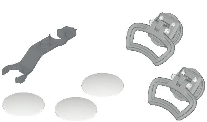
Commissioning only after all the installation 4.2 Scope of delivery
work has been completed and only after filling – DAIKIN EKHHP
the storage tank completely. – Bag of accessories (see fig. 4-1)
C (1x)
A (2x)
WARNING!
Cooling systems (heating pumps), climate D (1x)
control systems and heating devices that have
been set up and installed incorrectly can both
endanger life and health of people and be im- B (3x)
paired in their function.
● Work on the DAIKIN EKHHP (such as setup,
servicing, connection and initial start-up) is
only to be carried out by persons who are
authorised and who have successfully
A Handles (only required for C Hose connection piece for
completed qualifying technical or transport) safety overflow
vocational training and who have taken part B Cover screen D Spanner
in advanced training sessions recognised by Fig. 4-1 Contents of bag of accessories
the relevant responsible authorities for the
specific activity. These include in particular
certified heating engineers, qualified
electricians and HVAC specialists, who
because of their professional training and
expert knowledge, have experience in the
professional installation and maintenance of
heating, cooling and air conditioning systems
and heat pumps.
DAIKIN EKHHP Installation and operating instructions
DAIKIN Hot water heat pump
008.1423499_08 – 06/2020 – EN 94 x Set-up and installation
4.3 Set-up ● Remove packing and dispose of it in an environment-friendly
manner.
● Remove the cover plates on the storage tank (fig. 4-2, item B)
and unscrew the threaded pieces (fig. 4-2, item F) from the
CAUTION! apertures on which the handles are to be mounted.
● Screw handles (fig. 4-2, item A) into the threaded holes that
● Only erect the DAIKIN EKHHP when a suffi- are now free.
cient ground load-bearing capacity, of
1050 kg/m² plus safety margin, has been
assured. The ground must be flat and level.
● Outdoor installation is not permitted.
● Erection in explosion-risk environments is
not permitted.
● The DAIKIN EKHHP must only be set up in
non-hermetically closed rooms.
● The electronic control system must not be
subjected to atmospheric factors under any
circumstances.
● The storage tank must not be exposed to
continuous direct sunlight, as the UV
radiation and the effects of the weather will
damage the plastic.
● The DAIKIN EKHHP must be installed in a
manner protected from frost.
● Make sure that the supply company does
not provide corrosive domestic water.
– Suitable water treatment may be
required.
WARNING!
The plastic wall of the storage tank of the
DAIKIN EKHHP can melt under the effects of
external heat (>80 °C) and, in the extreme case,
can catch fire.
● Erect the DAIKIN EKHHP only at a minimum
distance of 1 m to other heat sources
(>80 °C) (e.g. electric heater, gas heater,
chimney) and flammable materials.
A Handle F Threaded piece
CAUTION! B Cover screen
Fig. 4-2 Attach handles
If the DAIKIN EKHHP is not erected ade-
quately lower the flat solar panels (the top ● Install the DAIKIN EKHHP at the installation site.
– Recommended distances:
edge of the of the storage tank is higher than the To the wall (rear): ≥200 mm.
bottom edge of the solar panels), the unpres- To the ceiling: ≥200 mm.
surised solar system in the outdoor area will be – Observe the tilt dimension (see chap. 10).
unable to drain completely. – Carefully transport the DAIKIN EKHHP, use the handles.
– When setting up the unit in a cabinet, behind panels or in
● Erect the DAIKIN EKHHP with a DrainBack other restricted conditions, sufficient ventilation (e.g.,
using ventilation gratings) must be ensured.
solar connection at a sufficient depth to the
– To avoid a circulation line, install DAIKIN EKHHP close to
flat solar panels (observe the minimum the draw-off location.
gradient in the solar connecting lines).
Installation and operating instructions DAIKIN EKHHP
DAIKIN Hot water heat pump
10 008.1423499_08 – 06/2020 – EN4 x Set-up and installation
4.4 Hydraulic connection If the installation conditions require the hydraulic
connection to be directly upwards, the cover
hood can be cut out along the broken line.
CAUTION!
If the DAIKIN EKHHP is connected to a cold
water line, where steel pipes are used, chips
can enter the special steel corrugated pipe heat
exchanger and remain there. This can lead to
contact corrosion damage and subsequently
to leakage.
● Flush the feed pipes before filling the heat
exchanger.
Fig. 4-4 Creating the hood cut-out
● Install contamination filter in the cold water
feed (see chap. 2.4.5).
– Pay attention to the stipulated tightening torque (see
chap. 4.1).
ONLY DAIKIN EKHHP500A*2V3 – Design the lines as such that the sound attenuation cowl
can be applied without any problem following assembly.
CAUTION!
If the heat exchanger for charging the pres-
surised solar system (see overview image on WARNING!
fig. 3-1, items 4+5) has an external heating There is a danger of scalding at hot water
unit (e.g. wood-burning boiler) connected to it, temperatures over 60 °C. This is possible,
an excessive flow temperature at these connec- when solar energy is used, with a con-
tions can damage or destroy the DAIKIN nected external heating device, when the
EKHHP. Legionella protection is activated or when
● The feed flow temperature of the external the domestic hot water target temperature
heater should be limited to max. 95 °C. is set higher than 60 °C.
● Install scald protection (hot water mixer
Requirement: Optional accessories (e.g. Solar) mounted on the (e.g. VTA32).
DAIKIN EKHHP according to the specifications in the instructions
included with the delivery.
– Water shortage protection: The temperature monitoring
● Check the cold water connection pressure (maximum 6 bar). of the controller safely switches off the DAIKIN EKHHP in
– At higher pressure in the drinking water line, a pressure the event of a water shortage. No additional water short-
reducer must be installed. age protection is needed in the construction. Neverthe-
● Remove the cover on the less, regular checking of the fill level is necessary in order
DAIKIN EKHHP. to ensure function as intended.
– Avoid damages caused by deposits and corrosion:
Observe the requirements for storage tank water (see
chap. 2.4.6).
Fig. 4-3 Remove the protective
cover.
● When using circulation brakes, fit them into the pipe
connections on the DAIKIN EKHHP.
● Create hydraulic connections on the DAIKIN EKHHP (see
fig. 4-5).
– Fig. 3-1 and tab. 3-1 give the position and dimensions of
the connections.
DAIKIN EKHHP Installation and operating instructions
DAIKIN Hot water heat pump
008.1423499_08 – 06/2020 – EN 114 x Set-up and installation
● Connect the drain hose to the connector for the safety
overflow (fig. 4-6 to fig. 3-1, item 23).
– Use transparent drain hose (draining water must be visi-
ble).
– Connect the drain hose to an adequately dimensioned
waste water installation.
– Drain should not be lockable.
Fig. 4-5 Hydraulic connection - legend see tab. 4-2
(Example EKHHP500A*2V3 with Solar and optional ex- Fig. 4-6 Installation of drain hose at safety overflow
ternal heat generator)
4.4.1 Optional: Connection of an external heat
1 Cold water connection generator
2 Hot water distribution network
3 Feed Solar or for other heat source* For support or as an alternative for heating by the heat pump you
4 Return Solar or for other heat source* can connect external heat generators (e.g. Solar, gas or oil boiler)
6 Circulation to the DAIKIN EKHHP.
7 Customer's side: Check valve, return valve
7a Circulation brakes (2 in number) Recommended accessory The heat supplied by the external heat generator must be added
8a Feed Solar or for other heat source* to the unpressurised storage tank water in the DAIKIN EKHHP
8b Return Solar or for other heat source* hot water storage tank.
9 Gas line (refrigerant)
● Carry out hydraulic connection in accordance with one of the
10 Liquid line (refrigerant)
two following possibilities:
CW Cold water a) DAIKIN EKHHP: unpressurised via connections
DHW (solar infeed and solar return) of the hot water tank
Hot water or
EKHHP b) Only EKHHP500A*2V3: via the integrated
DAIKIN heat pump internal unit pressurised solar heat exchanger.
EKSRPS4A – Fig. 3-1 and tab. 3-1 give the position and dimensions of
DAIKIN solar regulation and pump unit* the connections.
FLG FlowGuard - solar regulating valve with flow indicator* – Carry out hydraulic system incorporation in accordance
ERWQ
with fig. 4-5.
DAIKIN Heat pump external unit
FLS FlowSensor - solar flow and feed temperature measurement
– Pay attention to the stipulated tightening torque (see
PK Boiler circulation pump* chap. 4.1).
PZ Circulation pump* – Design the lines as such that the sound attenuation cowl
SK Solar panel field* can be applied without any problem following assembly.
SV Customer's side: Safety over-pressure valve
WEX External heat generator*
* Optional
Tab. 4-2 Legend for fig. 4-5
● Carefully insulate pipe lines against heat loss and so as to
avoid the formation of condensation (insulation thickness at
least 20 mm).
Installation and operating instructions DAIKIN EKHHP
DAIKIN Hot water heat pump
12 008.1423499_08 – 06/2020 – EN4 x Set-up and installation
4.5 Laying coolant lines 4.6 Pressure test and filling the coolant circuit
● Check whether oil trap arc necessary.
– Required if DAIKIN EKHHP is not installed at ground level RISK OF ENVIRONMENTAL
with the heat pump exterior unit (fig. 4-7, HO ≥ 10 m). DAMAGE!
– At least one oil trap arc must be installed every 10 m dif-
ference in height (fig. 4-7, H = clearance from oil trap arc Important information regarding the coolant
to oil trap arc). used.
– Oil trap arc only required in gas line.
● Install lines with bending unit and an adequate clearance to The complete heat pump system contains re-
electrical lines. frigerant with fluorinated greenhouse gases
● Only solder with light nitrogen flow (hard soldering only).
● Do not apply heat insulation to joins until after start-up (for
which damage the environment if released.
purposes of leakage search). Coolant type: R410A
● Establish flange connections and connect to the units. (
Pay attention to the tightening torque, see chap. 4.1). GWP* value: 2087,5
* GWP = Global Warming Potential
● Work on fixed cooling systems (heat pumps)
and air-conditioning systems can only be
performed by persons who hold a certificate
of competence for the European Region, in
B
accordance with the F-Gas Regulation (Ec)
No. 303/2008.
E
● Fill in the total coolant filling quantity on the
supplied lable on the heat pump exterior unit
(for information consult the installation
instructions for the heat pump exterior unit).
● Never allow coolant to be released into the
A atmosphere - always suction it off and recycle
using a suitable recycling device.
C
Ho
No additional coolant is required for the basic filling.
H
This is independent of the line length between the in-
ternal unit and external unit.
D
● Perform pressure test with nitrogen.
– Use nitrogen 4.0 or higher.
– Maximum 40 bar.
● After leak search is complete, completely drain.
A DAIKIN ERWQ ● Evacuate the lines (see installation instructions of the heat
B DAIKIN EKHHP pump external unit).
C Gas line ● Open stop valve on exterior unit completely until the stop.
D Liquid line Tighten loosely.
E Oil trap arc ● Reassemble valve caps.
H Height to 1st oil trap (max. 10 m)
HO Height difference between heat pump exterior unit and heat pump
interior unit.
Fig. 4-7 Oil trap arc coolant line
DAIKIN EKHHP Installation and operating instructions
DAIKIN Hot water heat pump
008.1423499_08 – 06/2020 – EN 134 x Set-up and installation
4.7 Filling the system with water 4.8 Electrical connection
WARNING! WARNING!
If you operate the DAIKIN EKHHP when the Touching live parts can result in an electric
storage tank is not completely full, damage to shock and lead to potentially fatal injuries and
the equipment may occur. burns.
● Fill the DAIKIN EKHHP only after all the ● Before beginning work on live parts,
hydraulic installation work has been disconnect all of the systems circuits from
completed. the power supply (switch off main switch,
● Observe the sequence during the filling disconnect fuse) and secure against uninten-
process. tional restart.
● Commissioning only after all the installation ● The electrical connection and working on the
work has been completed and only after electrical components should only be
filling the storage tank completely. performed by qualified electrical engineers
in compliance with valid standards and
The corrugated pipe heat exchangers must be filled guidelines as well as the specifications of the
before the storage tank. energy supply company and the instructions
The heat exchanger for connecting an optional heat given in this manual.
generator (fig. 3-1, item 14, only EKHHP500A*2V3) also needs ● Never carry out any structural changes to
to be filled if no optional heat generator is connected to it. This
heat exchanger, and the heating circuit of the external heat gen-
plug sockets or other electrical equipment
erator connected to it, should be filled first. components.
● The equipment covers and maintenance
opening covers must be re-fitted immedi-
ately after completion of the work.
UK only! CAUTION!
If filling or topping up the storage tank is done by
means of the boiler filling and drain valve, a CAUTION!
temporary filling loop must be used with the In the controller housing of the DAIKIN
appropriate backflow prevention device in EKHHP, in continuous running, elevated tem-
accordance with clause G24.2, Guidance to the peratures can be generated. This can result in
Water Supply (Water Fittings) Regulations currently-carrying wires from reaching higher
1999. temperatures during operation due to self-
heating. For this reason, these lines need to
Observe the information on the water connection and water have a continuous use temperature of 90 °C.
quality in accordance with Chap. 2.4.5 and 4.4.
● For the following connections, use only
4.7.1 Filling the hot water heat exchanger cables with a long-term use temperature
1. Open the shutoff valve for the cold water supply pipe. ≥90 °C:
2. Open the hot water tap connections so that the draw-off – Exterior heat pump unit
volume can be set as high as possible. – Voltage supply Booster-Heater
3. Once water has been discharged from the tap connections, – Contacts (connection HT/NT/Smart Grid)
do not interrupt the cold water flow; this will ensure that the
heat exchanger will be fully vented and that any impurities or – Network connections need to be executed as independent
residue will be discharged. power circuits.
– Ensure power cables, sensor cables and data bus cables are
4.7.2 Filling the storage tank laid separately from each other.
– Use only cable trunking with separate trays or cable trunking
See chap. 9.2.
with separators that ensure at least 2 cm spacing.
– Cable cross-overs are not permissible.
– For all the cables connected to the DAIKIN EKHHP effective
tension relief must be ensured in the controller housing using
cable ties (see fig. 4-8 to 4-10).
Installation and operating instructions DAIKIN EKHHP
DAIKIN Hot water heat pump
14 008.1423499_08 – 06/2020 – EN4 x Set-up and installation
4.8.1 Connection EKHHP on heat pump external unit,
mains connection Booster-Heater (BSH)
● Check the supply voltage (~230 V, 50 Hz).
● Disconnect the junction box of the domestic installation.
● Install the heat pump external unit.
● Lay the mains and communication cable (4 core, 0.75 mm²)
between heat pump external unit and DAIKIN EKHHP.
● Connect mains and communication cable to heat pump
external unit (see relevant installation instructions).
● Connect DAIKIN EKHHP to the heat pump external unit (see
fig. 4-11).
● Lay the cable (3 core, >1.5 mm²) for the power supply to the
Fig. 4-8 Tension relief using cable ties Booster Heater between distributor box of the house instal-
lation and the DAIKIN EKHHP.
● Connect the cable for power supply on the Booster Heaters to
the DAIKIN EKHHP (see fig. 4-11).
● Connect the cable for power supply to the Booster Heater on
the distributor box of the house installation (see fig. 4-11).
ERWQ02AAV3 Exterior heat pump unit
X1M Terminal rail on EKHHP
Fig. 4-11 Mains connection DAIKIN EKHHP
When switching off the heat pump external unit using a
Fig. 4-9 Click the holding clip in place and retain the cables with the ca-
switching system prescribed by the energy supply com-
ble ties pany (EVU), the DAIKIN EKHHP is switched off as well.
This complete switch-off of the heat pump external unit is an op-
tional installation and must only be carried out by experts.
Fig. 4-10 Check the holding force of the tension relief
DAIKIN EKHHP Installation and operating instructions
DAIKIN Hot water heat pump
008.1423499_08 – 06/2020 – EN 154 x Set-up and installation
4.8.2 High/low tariff mains connection (HT/NT) 4.8.4 Optional: Connection of an external heat
generator
if the external unit is connected to a high/low tariff mains con-
nection, the potential-free switch contact HT/NT of the receiver When using an external heat generator, this can be connected
that evaluates the signal emitted by the electrical supply using a potential-free switching contact (HT/NT) on the DAIKIN
company (EVU) (i.e. the HT/NT signal) must be connected to the EKHHP.
connections GND/IN1 of the DAIKIN EKHHP (see fig. 4-12).
If the potential-free switching contact is closed by an external
When the parameter [7-00] > 0 is set, certain system compo- heat generator, the DAIKIN EKHHP reduces its own heat gener-
nents are switched off in high tariff times (see chap. 7.5). ation in order to favour the external heat generator (settings see
The potential-free switching contact GND/IN1 can be designed chap. 7.5.2).
as a normally-closed or a normally-open switching contact.
a) If it is configured as a normally-open switching contact,
then the parameter [7-00] = 1 must be set.
When the EVU sends out the HT/NT signal, the switching
contact HT/NT is closed. The installation switches to
"Reduced Mode". If the signal is sent again, the potential-free
switching contact HT/NT opens and the system resumes GND + IN1 Connection potential-free switching contact on EKHHP
operation. WEX External heat generator
b) If it is configured as a normally-closed switching contact, X2M Terminal rail on EKHHP
then the parameter [7-00] = 2 must be set. Fig. 4-13 External heat generator electrical connection
When the EVU sends out the HT/NT signal, the switching
contact HT/NT is opened. The installation switches to
"Reduced Mode". If the signal is sent again, the potential-free
switching contact HT/NT closes and the system resumes
operation.
HT/NT High/low tariff mains connection (EVU receiver)
SG Smart Grid connection (EVU receiver)
GND+IN1 Connection HT/NT switching contact on EKHHP
GND+IN2 Connection Smart Grid switching contact on EKHHP
X2M Terminal rail on EKHHP
Fig. 4-12 Electrical connection HT/NT - and Smart Grid switching con-
tact
4.8.3 Connection EVU receiver (intelligent regulator
Smart Grid - SG)
Once the function is activated by the parameter [7-00] = 3 (see
chap. 7.5.2), the heat pump is changed to Stand-By, Normal or
an operating mode with higher temperatures, depending on the
signal from the energy supply company.
To do this, the potential-free switching contacts HT/NT + SG
of the EVU receiver need to be connected to the terminal rail
connections (GND+IN1) / (GND+IN2) of the DAIKIN EKHHP
(see fig. 4-12).
As soon as the function Smart Grid is active, the HT/NT function
is deactivated automatically. Depending on the value of the pa-
rameter [7-00], the heat pump is operated differently (see
tab. 7-3).
Installation and operating instructions DAIKIN EKHHP
DAIKIN Hot water heat pump
16 008.1423499_08 – 06/2020 – EN5 x Start-up
5 Start-up
5.1 Start-up
WARNING! 5.1.1 Requirements:
A DAIKIN EKHHP that is installed or started in- – The DAIKIN EKHHP system is set up and completely con-
correctly may not operate properly and is dan- nected.
– The coolant system is dehumidified and filled with the speci-
gerous for the health and safety of individuals. fied amount of coolant.
The DAIKIN hot water heat pump may only be – The hot water distribution network is bled and has the correct
started up by authorised and trained heating ex- pressure applied (see chap. 4.7).
perts. – The storage tank is filled up to the overflow (see chap. 9.2).
– Optional accessories have been mounted on and connected
up.
After the DAIKIN EKHHP was installed and connected com-
CAUTION! pletely, it will need to be undergo a one-time adaptation to the in-
stallation environment to be carried out by technical personnel
A DAIKIN EKHHP not put into operation (configuration of optional accessories, setting the parameters).
properly can lead to damage to property and the After this configuration is complete, the installation is ready for
environment. operation and the operator can make additional custom configu-
rations on it.
● Observe the relevant regulations of
The heating expert must instruct the user, generate the commis-
technology to prevent creation of corrosion sioning report and fill it in.
products and deposits. Minimum require-
ments regarding the quality of filling and 5.1.2 Start the system
supplementary water: ● Check all the points on the enclosed checklist. Document the
– Water hardness (calcium and magnesium, test result.
calculated as calcium carbonate): ● Switch on the power supply at the distributor box of the house
installation for the DAIKIN hot water heat pump.
≤ 3 mmol/l ● Switching DAIKIN EKHHP on.
– Conductivity: ≤ 1500 (ideal: ≤ 100) μS/cm ● Perform a test run:
– Chloride: ≤ 250 mg/l – Allow the temperatures to be displayed (see chap. 7.2.3).
– Sulphate: ≤ 250 mg/l – Test the hot water generation function. Select a higher set
hot water temperature so that the heating function is acti-
– pH value: 6.5 - 8.5. vated (see chap. 7.3.1).
● Sign the check list, together with the operator.
● If the above-mentioned minimum water Only if it is possible to answer all items on the check list by Yes,
quality requirements set by the local water is it allowed to commission and hand over the DAIKIN hot water
supply company cannot be guaranteed, heat pump to the operator.
suitable water treatment measures must be
taken.
● The domestic water quality must comply with
the EU Guideline 98/83 EC and the
regionaly-applicable regulations.
CAUTION!
If the DAIKIN EKHHP is started when the
storage tank is not completely full a reduction
in output may arise when heating, or to
destruction of the integrated Booster Heater
(BSH) and may cause an electrical fault.
● DAIKIN EKHHP only to be operated with full
storage tank.
DAIKIN EKHHP Installation and operating instructions
DAIKIN Hot water heat pump
008.1423499_08 – 06/2020 – EN 175 x Start-up
Check list for start-up
1st. DAIKIN EKHHP erected in accordance with the requirements and instructions in chap. 4 and shows no damage? Yes
2. Minimum distance between the DAIKIN EKHHP and other sources of heat (>80 °C) of 1 m? Yes
3. Booster-Heater:
– Does the mains connection comply with the regulations and is the mains voltage 230 volts at 50 Hz? Yes
– Has the residual current device been fitted in accordance with the individual country-specific regulations? Yes
4. Is the heat exchanger for domestic hot water heating in the DAIKIN EKHHP full and has it been bled? Yes
4.1 Only EKHHP500A*2V3: Is the heat exchanger filled for the connection of an optional heat generator? Yes
5. Is the storage tank full with water to the overflow point? Yes
6. Is the safety overflow connection connected to an open drain? Yes
7. Is the water pressure on the sanitary side < 6 bar? Yes
8. Are all hydraulic connections tight (no leaks)? Yes
9. Have the parameters been set on the controller in accordance with the structural conditions, possibly connected Yes
accessories and the user stipulations?
10. Is the parameter [7-02] set to the value 0? Yes
11. Does the installation operate without faults? Yes
12. Has the operating manual been handed over, and has the owner been instructed? Yes
Location and Date: Signature of installer:
Signature of operator:
Installation and operating instructions DAIKIN EKHHP
DAIKIN Hot water heat pump
18 008.1423499_08 – 06/2020 – EN6 x Decommissioning
6 Decommissioning
6.1.1 Draining the storage tank
● DAIKIN Disconnect the EKHHP from the power supply.
WARNING! ● Remove connection piece (fig. 6-1, item C) from safety
Danger of scalding and flooding when overflow (fig. 6-1, item B).
● Connect the drain hose to the hose connection piece (item C)
opening the solar return flow coupling or hot and to a waste water drainage point which is at least at
water connections due to escaping hot water. ground level.
● Draining the storage tank only Alternatively, you can use the optional KFE filling
– after it has cooled down for a long enough connection (KFE BA).
period,
– with a suitable device for the safe draining
or catching of escaping water,
– wearing appropriate protective clothing.
6.1 Temporary shutdown
CAUTION!
A shutdown hot water heat pump can freeze in
the event of frost and may suffer damage as a
B Safety overflow C Hose connection piece for
result. safety overflow
E Threaded piece
● Drain the water out of the shutdown hot water
Fig. 6-1 Connecting the drain- Optional: Removing the connec-
heat pump if there is a risk of frost. age hose tion piece from the safety overflow
● If the hot water heat pump is not drained and
there is a risk of frost, the power supply must ● Remove the cover plate
from the filling and
be ensured and the external main switch emptying fitting. E
must remain switched on.
If the DAIKIN EKHHP is not needed for a long time, it can be tem-
porarily decommissioned.
However, DAIKIN recommends not disconnecting the system
from the power supply, but just switching it off (actuate button
).
The system is then protected from frost.
Fig. 6-2 Unscrew threaded piece
If it is not possible to guarantee the power supply when there is
danger of frost, ● Place a suitable collection trough beneath the filling and
– the DAIKIN EKHHP must be fully drained of water. emptying fitting.
● Unscrew the threaded piece (fig. 6-3, item E) at the filling and
draining connection, and remove the plug (fig. 6-3, item F)
If there is a danger of frost and the power supply cannot
and immediately screw in the pre-assembled hose
be guaranteed for just a few days, the unit's excellent
connector (fig. 6-1, item C) into the filling and draining
heat insulation means that the DAIKIN EKHHP does
connection (fig. 6-3) again.
not have to be drained, provided that the storage tank
temperature is monitored regularly and does not fall
below +3 °C.
However, this does not provide frost protection for the con-
CAUTION!
nected heat distribution system.
Storage water will gush out as soon as the
sealing plug is removed.
There is no valve and no non-return flap on the
filling and draining connection.
DAIKIN EKHHP Installation and operating instructions
DAIKIN Hot water heat pump
008.1423499_08 – 06/2020 – EN 196 x Decommissioning
6.2 Final shutdown
WARNING!
Cooling systems (heat pumps), climate control
systems and heating devices that are incorrectly
dismantled can both endanger the life and
health of people and exhibit impaired function
during start-up.
At normal atmospheric pressure and ambient
temperatures, liquid coolant vapourises so
Fig. 6-3 Screwing pre-assembles connector into the filling and drain-
suddenly that on contact with skin or eyes it
ing connection can cause the tissue to freeze (danger of going
blind).
6.1.2 Draining the hot water circuit
● Work on the DAIKIN EKHHP (such as
● Close the cold water supply to the DAIKIN EKHHP.
dismantling components, temporary or final
● Separate the cold water supply pipe to the DAIKIN EKHHP
and allow the hot water distribution network to empty out. shutdown of system) is only to be carried out
● Isolate the cold water supply and hot water outlet from the by persons who are authorised and who have
DAIKIN EKHHP. successfully completed qualifying technical
● Connect the drain hoses to cold water supply and hot water
outlet so that the end of the hose is located just above ground
or vocational training for the specific
level. activity and who have taken part in advanced
● Allow heat exchanger to drain according to the siphon training sessions recognised by the relevant
principle. responsible authorities. These include, in
particular, certified heating engineers,
qualified electricians and HVAC
specialists, who on account of their profes-
sional training and expert knowledge,
have experience in the professional instal-
lation and maintenance of heating, cooling
and air conditioning systems and heat
pumps.
● You must observe the warning and safety
instructions in the installation manual on
working in the coolant system.
A final shutdown may be necessary if
– the system is defective and is being dismantled and disposed
of.
– components of the system are defective, are being disman-
tled and replaced.
– the system or parts of the system are being dismantled and
reassembled in another location.
The DAIKIN EKHHP is designed to be environmentally friendly
and easy to install: the jobs described above can therefore be
carried out in an efficient and environmentally-friendly manner.
When changing location or replacing parts on the coolant system
pipework:
● Pump the coolant back into the external heat pump unit (see
installation and operating guide for the particular external
heat pump unit).
When disposing of the machine or replacing parts in the coolant
system:
● Suction the coolant from the machine and recycle (see instal-
lation and operating guide for the particular external heat
pump unit).
Installation and operating instructions DAIKIN EKHHP
DAIKIN Hot water heat pump
20 008.1423499_08 – 06/2020 – EN6 x Decommissioning
CAUTION!
Coolant escaping from the system causes long-
term damage to the environment.
Mixing different kinds of coolant can result in
hazardous toxic gases being released. Mixing
with oils when coolant escapes can lead to the
soil being contaminated.
● Never allow coolant to be released into the
atmosphere - always suction it off and recycle
using a suitable recycling device.
● Always recycle coolant, in so doing keeping it
separated from oils and other additives.
● Only store different types of coolant
separately, in suitable pressure vessels.
● Dispose of coolants, oils and additives
properly and in accordance with the appli-
cable national regulations of the country it is
being used in.
● Decommissioning a DAIKIN EKHHP (see chap. 6.1).
● Disconnect the DAIKIN EKHHP from all electrical connec-
tions, refrigerant and water connections.
● Dismantle the DAIKIN EKHHP or components in accordance
with the installation guide in reverse order.
● DAIKIN EKHHP disposed off in a professional manner.
Recommendations for disposal
The DAIKIN EKHHP has an environmentally friendly design.
During the disposal process, the only waste created is that which
can be used for material or thermal recycling. The materials used
that are suitable for recycling can be sorted into individual types.
DAIKIN has complied with the standards for environ-
mentally-friendly disposal as a result of the environ-
mentally-friendly design of the DAIKIN EKHHP. Proper
disposal in compliance with the respective national reg-
ulations of the country of use is the responsibility of the
user/owner.
The designation of the product means that electrical
and electronic products may not be disposed of
together with unsorted domestic waste.
Proper disposal in compliance with the respective
national regulations of the country of use is the respon-
sibility of the user/owner.
– Disassembly of the system, handling of coolant, oil and other
parts may only be carried out by a qualified fitter.
– Disposal may only be carried out by an organization that
specialises in reuse, recycling and recovery.
Further information is available from the installation company or
the responsible local authorities.
DAIKIN EKHHP Installation and operating instructions
DAIKIN Hot water heat pump
008.1423499_08 – 06/2020 – EN 217 x Operation, Parameters
7 Operation, Parameters
You can switch the system off and on at the controller for the If the hot water generation is operating in "High Output" mode
DAIKIN EKHHP, you can also set the hot water generation and , the icon flashes .
timer programmes, carry out settings for the operating mode of
The symbol flashes more quickly during thermal disinfection
the heat pump external unit and change parameter settings.
(Legionella mode).
The available parameters and their setting possibilities are de-
scribed in chap. 7.5.1 and 7.5.2. 34 - Sensor number display
This code refers to the temperature displays (see chap. 7.2.3).
Settings for a solar system connected to the EKHHP of a DAIKIN
type must be carried out on the controller of the solar system. 35 - Display Time
The clock display shows the current time. The set switching time
is indicated in the display in the programming mode.
7.1 Displays and function of the operating
elements 36 - Display Weekday
This display shows the current day of the week. The set day is in-
dicated in the display in the programming mode.
CAUTION! 37 - Display refrigerant compressor active
This icon shows that the refrigerant compressor is active in the
Never operate the operating elements on the external heat pump unit.
controller with a hard, pointed object. This can 38 - Display switching time programme switched on
cause damage and can cause the control unit to This icon shows that the timer function is switched on.
malfunction. 39 - Display active switching times
These icons indicate the active switching times of the current day
of the week.
40 - Display off status in timer programme
This icon shows that the current switching time has switched the
system off.
41 - Display Booster-Heater (BSH) connected
This icon indicates that the support in hot water heating is active
by the Booster-Heater (BSH).
42 - Display external signal (HT/NT/Smart Grid)
This icon indicates that the DAIKIN EKHHP is influenced in its op-
erating mode by closed switching contacts (see Parameter
[7-00].
43 - Display function "defrost" active
This icon shows that the operating mode "defrost" or start-up is
active.
44 - Display storage tank temperature
This symbol appears if the hot water temperature in the inte-
grated storage tank is displayed.
Fig. 7-1 For display and operating elements of the control - The icon is also shown if the temperature target value is set in
legend see tab. 3-1 and the following description programming mode.
30 - Key "On / Off" 45 - Display operating mode "Automatic"
Switch on and off the DAIKIN EKHHP. When the hot water heat This icon indicates that the heat pump is running in the "Auto-
pump is switched on, the operating display LED lights up red. matic" mode.
Pressing the key too often repeatedly can cause the system 46 - Display external temperature active
to malfunction (maximum of 20x per hour). If this icon flashes, the outside temperature is shown in the tem-
31 - Operating display LED perature display (47) (see chap. 7.2.3).
The operating display LED lights up during hot water heating op- 47 - Display hot water temperature or other
eration. The LED flashes if there is a malfunction. If the LED is temperature values
switched off, the DAIKIN EKHHP is switched off. The display shows various temperature values (see chap. 7.2.3).
32 - Display operating mode "Low Noise" 48 - Display "Function not available"
This icon indicates that the heat pump external unit is running in This icon is always shown if an option that has not been installed
low noise mode. is selected or if a function is not available.
In this operating mode the output of the system is reduced so that
49 - Display parameter setting mode active
the operating noise of the external heat pump unit is reduced.
The display indicates that the user can see and change the pa-
33 - Display hot water generation active rameter settings.
This icon indicates that the hot water heating mode is active.
Installation and operating instructions DAIKIN EKHHP
DAIKIN Hot water heat pump
22 008.1423499_08 – 06/2020 – ENYou can also read