Installation Manual: Mazda CX-5 (2017-2018) Power Lift Gate System - Page 1 of 11
←
→
Page content transcription
If your browser does not render page correctly, please read the page content below
Installation Manual:
Mazda CX-5 (2017-2018)
Power Lift Gate System

             Page 1 of 11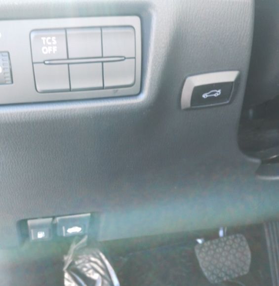
NOTE: Installation Precaution

1. It is recommended to have this product installed by a professional to avoid damage caused by improper
installation.

2. Do not attempt to disassemble or modify any components included within the kit. Unapproved modifications
or evidence of tampering will void any warranty included with the product.

3. Before installation, inspect the vehicle's controls and interior/exterior for any damage or malfunctioning
components. Report any damage or non conformities to the customer prior to installing the product.

4. Inspect the factory lift gate for proper operation and function of lights before installing this product. Improper
opening or closing of the lift gate may interfere with the functionality of the Power Lift Gate System.

5. It is recommended to remove or cover any item of clothing (belt buckles, jeans rivets, buttons, etc) prior to
installation of this accessory to prevent damage incurred to the vehicle during the installation.

6. Interior panels that have been removed should be set aside somewhere safe during the installation process
to avoid damage.

7. When routing and securing wiring harnesses, care should be exercised to avoid any hot, sharp, or moving
objects in the vehicle such as steering column, pedals, dash bracing, HVAC components, etc.

8. Do not deviate from methods of installation in this document. Any damage caused by improper wire routing,
incorrect connections, wiring, etc. is not covered under the warranty.

9. Disconnect the negative (-) battery terminal before proceeding to installation. Wait at least 2 minutes after
disconnecting the negative (-) battery terminal to disable the SRS and other systems in the vehicle. Any dam-
age caused from failure to disconnect the battery is not covered under the warranty.

10. After installation, you must manually close the lift gate to initialize the Power Lift Gate System.

                                                  Page 2 of 11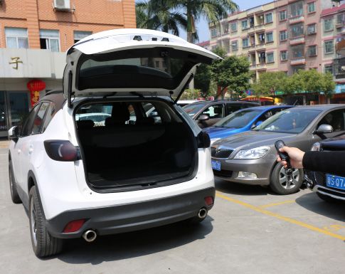
Kit Details

              Page 3 of 11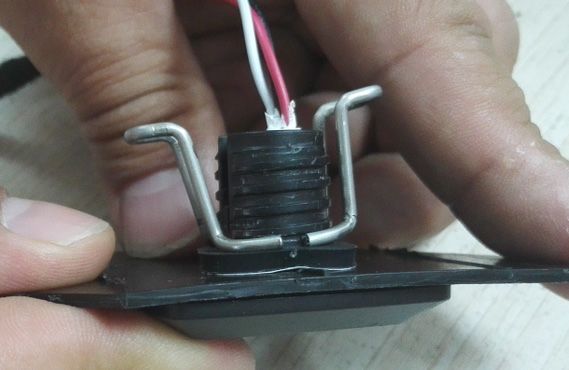
Kit Details

              Page 4 of 11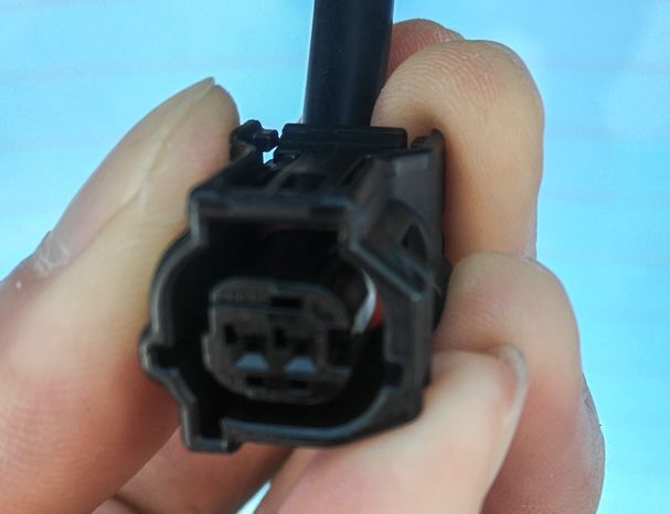
PREPARING FOR INSTALLATION

INSTALLATION PREPARATION

   Before starting installation

1. Familiarize yourself with the installation instructions.

2. Inspect kit components to verify everything is pres-
ent, there is no damage, and to familiarize yourself with
the parts.
                                                                 Negative Battery
 VEHICLE PREPARATION                                             Cable

1. Place protective coverings on vehicle.

2. Apply protective tape to all points before prying.

3. "IMPORTANT........IMPORTANT"
      Disconnect Negative Battery
      Cable

INSTALLATION:

1. Using a moulding remover, disengage the clips
   and remove the lift gate pull handle cup.

2. Using a moulding remover, carefully disengage
   any clips and remove the interior trim panels from
   the lift gate. Make sure to exercise care and dis-
   connect any electrical connectors to interior lights
   before pulling too hard, to avoid damage to wiring
   harnesses.

                                                  Page 5 of 11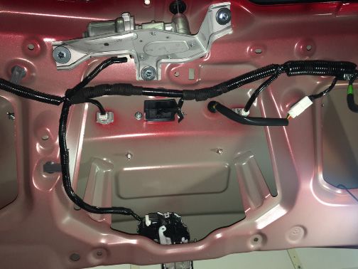
3. Using a helper or supporting brace, support the
   lift gate in the full opened position.

4. Using a pry tool, remove the clip on the end of
   the OEM gas support struts for the lift gate.

  Exercise caution when removing the sup-
  port struts, as the lift gate is very heavy once
  removed.

5. Using a pry tool, remove the clip to disconnect
   the OEM gas support strut from the OEM body
   strut mount.

6. Attach the Power Lift Motor to the body mount
   and the lift gate ball mount, noting the Left and
   Right designations marked on each Power Lift
   Motor. Verify the Power Lift Motor is securely at-
   tached to both mounts. The end with the wiring
   harness should be towards the vehicle's body.

  Repeat for the opposite side.

                                                Page 6 of 11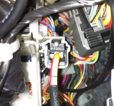
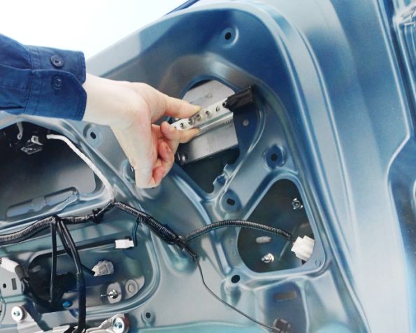
7. Remove the factory rubber grommet. Route
   the wiring harness through the hole and into the
   lift gate, seating the included grommet on the
   harness into the cavity from where the factory
   grommet was removed. Repeat for the opposite
   side.

  NOTE: Limit motor wiring harness slack as
  much as possible. Extra slack can get caught
  in weather seal, causing liftgate to leak.

8. Mount the main control module to the lift gate
   brace using the supplied mounting bracket.
   Route the Power Lift Motor wire harnesses to
   the main control module and connect to the cor-
   responding connectors.

9. Locate the OEM outside opener switch connector,
   on the rear of the switch assembly. Disconnect
   the OEM connector, and connect our T-Harness
   in line with the outside opener switch.

                                              Page 7 of 11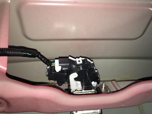
10. Locate the OEM power latch. Disconnect the
  OEM connector, and connect our T-Harness in
  line with the power latch assembly.

11. Remove the driver's side lower dash panel.
   Locate the main power wire, and connect in line
   with the supplied T-Harness.

12. Locate the OBDII connector. Disconnect the
  connector from it's mounting location and con-
  nect into the supplied T-Harness. Mount the
  T-Harness connector into the factory location.

13. Route the main wiring harness along the driver's
   side floor under the scuff plates to the luggage
   compartment area.

14. Route the main wiring harness up towards the
  headliner along the path shown.

                                               Page 8 of 11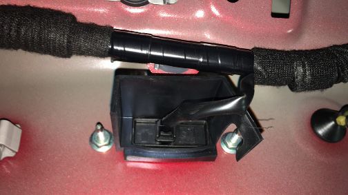
15. Route the main wiring harness through the
  OEM grommet and into the lift gate. Use a fish
  tape to help in pulling the harness through the
  factory wiring boot. Exercise care not to dam-
  age the harness or connectors when pulling
  the harness through the boot. Route the main
  wiring harness along the factory wiring harness
  to the main control module and connect to the
  main control module.

   Note: Spraying a small amount of soap/water
   solution into the OEM wire harness boot will
   help in pulling the wiring harness through
   easily.

16. Locate small plaque for rear button placement.

17. Using the supplied drill bit, drill a hole through
  the center of the small plaque.

18. Remove the orginal nut from the button. Insert
  the button through hole drilled in the small-
  plaque. Install silicon gromet and sandwich
  plaque between button and gromet. Tighten
  sping clip until flush with silicon gromet. Verify
  button is secure.

   NOTE: Do not reuse original nut from button.

                                                   Page 9 of 11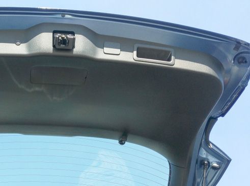
19. Mount the open/close button and secure with
  the nut. Connect to the main control module.

20. Mount the interior open/close button in the
  driver's side lower dash panel and secure with the
  nut. Connect to the wiring harness and reinstall
  the driver's side lower dash panel.

21. IMPORTANT: Prior to closing, ensure door
  panel is re-installed. Manually close the lift
  gate to initialize the Power Lift Gate System.
  Function test the system to verify proper
  operation.

                                                Page 10 of 11
THESE POINTS MUST BE CHECKED TO ENSURE A QUALITY INSTALLATION
Head Light Massage Seats (if equipped)
If the warning lights remains on, it may
indicate a system malfunction. Power Side Mirrors (if equipped)
High Beams
Side Mirror Defogger (if equipped)
Turn Signal Lights
Front Windshield Defogger (if equipped)
Tail Lights
Navigation System (if equipped)
Stop Lights
Rear Sunshade (if equipped)
Backup Lights
Cruise Control Light (if equipped)
Hazard Lights
Steering Wheel Audio Control
Marker Lights (if equipped)
HVAC
Dome/Courtesy Lights
Power Locks (if equipped)
Panel/Switch Illumination
Accessory Controls/Illumination Power Windows (if equipped)
(if equipped)
Rear Window Defogger Gauges
(if equipped)
Front Wiper/Washer
Key Sensor Buzzer
Hood Latch Release
Fog Lights (if equipped)
Day Time Running Lights Passenger Air Bag Switch (if equipped)
(if equipped)
Trunk/Tailgate/Bed Lights Rollover Side Curtain Air Bag Switch (RSCA)
(if equipped)
Glove Box Light (if equipped) Horn
ABS Light (if equipped) Seat Belt Warning Light
If the warning lights remains on, it may
Rear Wiper/Washer (if equipped) indicate a system malfunction.
Air Bag Warning Light
Clock (if equipped) If the warning lights remains on, it may
indicate a system malfunction.
Accessory Power Socket Lamp Failure Sensor
(if equipped) If the warning lights remains on, it may
Starter indicate a system malfunction.
Track/Skid Control Light (if equipped)
Audio/Video (if equipped) If the warning lights remains on, it may
indicate a system malfunction.
Tire Pressure Monitoring System (TPMS)
Power Sliding Door (if equipped)
Prior to TPMS activation and Pre-Delivery
Service (PDS) of the vehicle the TPMS light will
Convenience Memory Settings blink when IG is turned on. After TPMS activa-
(if equipped) tion and PDS of the vehicle the TPMS light will
illuminate for a few seconds and go off when IG
Heated Seats (if equipped) is turned on.
Page 11 of 11You can also read