INSTALLATION MANUAL RPTR-734/230/OBA - REV: A (2/13/2020) Kleinn Air Horns 2020, All rights reserved - Kleinn Air ...
←
→
Page content transcription
If your browser does not render page correctly, please read the page content below
RPTR-734/230/OBA
INSTALLATION MANUAL
           REV: A (2/13/2020)

  © Kleinn Air Horns 2020, All rights reserved.
           PO Box 91278 Tucson, AZ 85752
               Phone: (520) 579-1531
               Web: www.Kleinn.com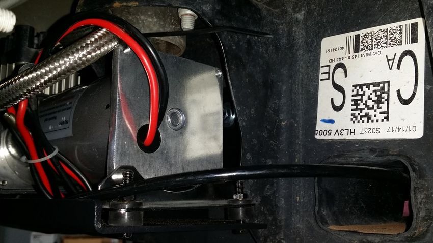
RPTR-734/230/OBA
                                         Installation and Operation Manual

                          This digital PDF is interactive.
                          Please save ink and paper…

       Open interactive manual using Adobe Reader ®
                     on PC, MAC, and all smart devices

Go to Table of Contents                PG 2/44                 REV: A (2/13/2020)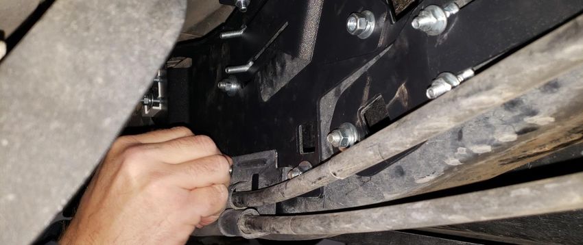
RPTR-734/230/OBA
                                                                                    Installation and Operation Manual
Table of Contents
1.    LIST OF FIGURES .................................................................................................................................................5
2.    How to Use this Manual .....................................................................................................................................6
     2.1. Interactive Manual using Adobe Reader ....................................................................................................6
     2.2. Your Kit SKU Number and this Manual.......................................................................................................6
     2.3. Illustration/Photo Details and Orientation.................................................................................................6
3.    Safety First ..........................................................................................................................................................7
     3.1. Before You Start .........................................................................................................................................7
     3.2. Know these Special Callouts .......................................................................................................................7
4.    Application Chart ................................................................................................................................................8
     4.1. 100% Direct Bolt-On Vehicle List ................................................................................................................8
     4.2. **Excluded Vehicles ...................................................................................................................................8
     4.3. Aftermarket Product Compatibility ............................................................................................................8
5.    Installation Overview..........................................................................................................................................9
     5.1. Kit Layout and Systems Location(s) ............................................................................................................9
     5.2. Approximate Installation Time ................................................................................................................ 10
     5.3. ***Quick Install Outline ........................................................................................................................... 10
6.    List of Tools and Supplies ................................................................................................................................ 11
     6.1. Standard Tool List (Required) .................................................................................................................. 11
     6.2. Special Tool List (Recommended) ........................................................................................................... 11
     6.3. Shop Consumables List (Recommended) ................................................................................................ 11
7.    Parts List .......................................................................................................................................................... 12
     7.1. Parts List Covers following SKU Numbers ............................................................................................... 12
     7.2. Pre-Packaged Electro-Mechanical Items ................................................................................................. 12
     7.3. Air Fittings and Related Items ................................................................................................................. 13
     7.4. Electrical Small Components and Related Items ..................................................................................... 15
     7.5. Bolt-On Mounting Brackets & Special Hardware .................................................................................... 16
     7.6. Hardware/Fasteners ................................................................................................................................ 17
8.    On-Vehicle Electrical Installation..................................................................................................................... 20
     8.1. Relay and Fuse Diagram for Air Horn System.......................................................................................... 20
     8.2. Suggested Wire Routing for Air Horn System ......................................................................................... 21
     8.3. Disconnect Vehicle Battery(s).................................................................................................................. 21
     8.4. Connect Wiring to Relay(s) and Fuse(s), then Attach to Vehicle............................................................. 21

Go to Table of Contents                                                        PG 3/44                                                          REV: A (2/13/2020)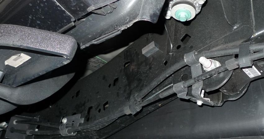
RPTR-734/230/OBA
                                                                                 Installation and Operation Manual
      8.5. Connect partial length of wiring to Air Horn Solenoid(s) ........................................................................ 22
      8.6. Connect partial length of wiring to Pressure Switch ............................................................................... 22
9.     Bench Assembly Steps ..................................................................................................................................... 23
      9.1. Disassemble 730/230 Horn Kit from Box ................................................................................................ 23
      9.2. Assemble Air Tank Fittings to Air Tank .................................................................................................... 23
      9.3. Attach Air Tank Straps to Tank Bracket ................................................................................................... 24
      9.4. Ore-Lock to Brackets Installation ............................................................................................................ 25
      9.5. Air Horn Driver Hardware Attachment.................................................................................................... 26
10. On-Vehicle Mechanical Assembly Steps .......................................................................................................... 27
      10.1. Nut Plate Installation ............................................................................................................................... 27
      10.2. Knurled Carriage Bolt Installation (“Knurled Bolt Stack-Up”).................................................................. 29
      10.3. Tank Bracket Installation and Temporary Tightening ............................................................................. 30
      10.4. Compressor Bracket Installation and Final Tightening ............................................................................ 31
      10.5. Attach Compressor to Bracket ................................................................................................................ 32
      10.6. Air Tank Installation ................................................................................................................................. 34
      10.7. Drain Valve Skid Plate Installation ........................................................................................................... 35
      10.8. Connect Remote Quick Connect Kit to Vehicle ....................................................................................... 36
      10.9. Main Horn Bracket Installation................................................................................................................ 37
      10.10. Medium Horn Bracket Installation. ....................................................................................................... 39
      10.11. Air Horn Driver Installation.................................................................................................................... 40
      10.12. Connect Air Tubing to Air Horn Driver .................................................................................................. 41
      10.13. Re-attach Trumpets to Air Horn Drivers ................................................................................................ 41
11. Initial Testing of Kit .......................................................................................................................................... 42
      11.1. Reconnect Vehicle Battery(s) .................................................................................................................. 42
      11.2. Test Air Compressor ................................................................................................................................ 42
      11.3. Test Train Horns....................................................................................................................................... 42
      11.4. Test Quick Connect Coupler .................................................................................................................... 42
12. General Operation of Kit ................................................................................................................................. 43
      12.1. Compressor Operation ............................................................................................................................ 43
      12.2. Horn Operation........................................................................................................................................ 43
13. Routine Maintenance ...................................................................................................................................... 43
14. Warranty Information ..................................................................................................................................... 44

Go to Table of Contents                                                       PG 4/44                                                      REV: A (2/13/2020)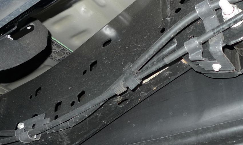
RPTR-734/230/OBA
                                                                               Installation and Operation Manual
1. LIST OF FIGURES
Figure 1 - Top View showing Kit Layout (2018 Crew Cab Shown) ..............................................................................9
Figure 2 - Suggested Ignition Relay Diagram for 730/230/OBA .............................................................................. 20
Figure 3 - Suggested Wire Routing for Horn, Air Compressor, and Pressure Switch .............................................. 21
Figure 4 - Air Fittings installed in Air Tank with locations ....................................................................................... 23
Figure 5 - RAPTOR-202 Tank Straps Formed and Attached (Shown without Air Tank and mis-aligned) ................ 24
Figure 6 - RAPTOR-303 attached to RAPTOR-301 ................................................................................................... 25
Figure 7 - Ore Locks attached to RAPTOR-301 and RAPTOR-303 (734 KIT ONLY) ................................................... 25
Figure 8 - RAPTOR-301, 302, 303 with Air Horn Driver Hardware circled (shown on frame) ................................. 26
Figure 9 - Frame Hole Locations for RAPTOR-203; below front door ..................................................................... 27
Figure 10 - Passenger Frame Rail Hole Locations, under rear door ........................................................................ 27
Figure 11 - RAPTOR-203 with #10 Inserted ............................................................................................................. 28
Figure 12 - RAPTOR-203 Insertion Method and Tightened to Frame. .................................................................... 28
Figure 13 - Knurled Bolt Installation (Common throughout) .................................................................................. 29
Figure 14 - Knurled Carriage Bolt “Stack-up” (Common throughout) ..................................................................... 29
Figure 15 - RAPTOR-201 Hardware Location (left side) .......................................................................................... 30
Figure 16 - RAPTOR-201 Hardware Location (right side) ........................................................................................ 30
Figure 17 - RAPTOR-201 Bolted to Frame (Compressor Bracket also shown attached) ......................................... 30
Figure 18 - RAPTOR-101 Mounted on top of RAPTOR-201 ..................................................................................... 31
Figure 19 - Compressor Mounted on RAPTOR-101 ................................................................................................. 32
Figure 20 – Standard Air Compressor fasteners “Stack-Up” ................................................................................... 32
Figure 21 - Compressor installed. Leader Hose Zip-tied to Compressor end plate hole......................................... 33
Figure 22 - Air Compressor Filter Remote Tubing shown attached ........................................................................ 33
Figure 23 - Rubber Strips Attached to Tank Bracket and Tank Straps..................................................................... 34
Figure 24 - Air Tank Final Installed .......................................................................................................................... 34
Figure 25 - RAPTOR-206 Lined Up with RAPTOR-201.............................................................................................. 35
Figure 26 - RAPTOR-206 Installed on Tank Bracket ................................................................................................. 35
Figure 27 – Example of Air Coupler Mounted To Bumper ...................................................................................... 36
Figure 28 - Driver's Side Frame Rail under rear door .............................................................................................. 37
Figure 29 – Main Horn Brackets Mounting Holes in Frame .................................................................................... 37
Figure 30 - View of Frame with Frame Clip location circled; RAPTOR-301, 302, 303 shown installed ................... 38
Figure 31 - Factory Frame Clip Reinserted into RAPTOR-301 ................................................................................. 38
Figure 32 - Reinstalling brake bracket over RAPTOR-301 ....................................................................................... 39
Figure 33 - Medium Horn Bracket Mounting Points ............................................................................................... 39
Figure 34 – Air Horn Layout (730 Horns shown with Trumpets attached); same for 734/230 Kits ........................ 40
Figure 35 - Air Horn Driver with Hardware Installed ............................................................................................... 40
Figure 36 – Air Horn Drivers Installed ..................................................................................................................... 40
Figure 37 - Air Line Routing Through Frame Crossmember .................................................................................... 41

Go to Table of Contents                                                    PG 5/44                                                    REV: A (2/13/2020)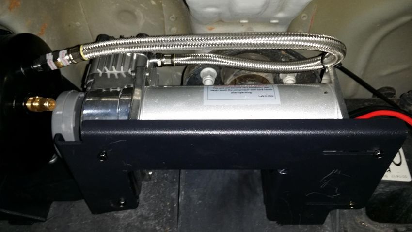
RPTR-734/230/OBA
                                                          Installation and Operation Manual
2. How to Use this Manual
2.1.    Interactive Manual using Adobe Reader
    It is recommended to open this digital PDF using Adobe Reader ® to take advantage of following key
    features:

    •   Hyperlinks (blue underlined text) allow access to additional content via internet; click/tap to activate
           o Includes Installation Figures and “Figure xx”
    •   Table of Contents page allows easily navigating this manual; click/tap any section line to go to it
    •   Bookmarks allow quickly navigating to any section; click/tap
    •   Zoom IN on pictures by pressing “CTRL and +” at same time on PC, or pinch in on smart devices
    •   Zoom OUT on pictures by pressing “CTRL and -” at same time on PC, or pinch out on smart devices

    To install Adobe Reader ®
    On PC, or Mac

    •   visit https://get.adobe.com/reader/otherversions/

    On Android, iPhone/iPad, and Windows devices,

    •   visit https://acrobat.adobe.com/us/en/acrobat/mobile-app.html

2.2.    Your Kit SKU Number and this Manual

This manual covers installation, testing, and operation of following SKU part numbers

        2.2.1. RAPTOR-230 (i.e., 230 Train Horn with On-Board Air System)
        2.2.2. RAPTOR-734 (i.e., 730 Train Horn with On-Board Air System)
        2.2.3. RAPTOR-OBA (i.e., On-Board Air System)
        NOTE: Illustrations and pictures contained herein may represent only one kit part number. Where
        critical differences exist between kits (i.e., different parts, orientation, mounting points, etc.), additional
        text, or necessary graphics are provided to minimize confusion.

Parts list explicitly state kit differences with (BOLD TEXT) inside parenthesis, shown below part number.

2.3.    Illustration/Photo Details and Orientation

        This manual may use digitally created illustrations, and/or actual photos of example vehicle. These
        graphics may not include exact items found on your vehicle (i.e., electrical wiring, fuel lines, body panels,
        etc.). Illustrations typically will be missing details and are for clarity to show critical mounting locations
        and orientation on vehicle.

        FRONT

Go to Table of Contents                                PG 6/44                                     REV: A (2/13/2020)
RPTR-734/230/OBA
                                                        Installation and Operation Manual
                                 Throughout this manual yellow arrows with text reading “FRONT”, may be
                                 present over illustrations and pictures. These arrows specify direction toward
                                 front of vehicle and provide clarity to how illustration is viewed.

3. Safety First
3.1. Before You Start

Read manual thoroughly before starting installation of this kit. Verify you have all parts listed and that you
clearly understand this installation procedure. Contact Kleinn technical support for any questions.

Installation of this kit requires moderate mechanical aptitude; seek professional help if you’re not competent
using hand tools in tight uncomfortable spaces, and around possibly rusted and sharp vehicle parts.

Before starting, obtain proper tools required to perform installation correctly, adequate lighting, eye protection,
hearing protection for operating train horns, and hand protection to guard against sharp edges and metal burrs,
which may be present on kit parts and vehicle parts.

3.2. Know these Special Callouts

Throughout this manual the following words may be used; be aware of their meaning and application.

CAUTION: means damage could occur to vehicle, or kit parts during, or after installation

WARNING: means injury could occur to you or others, including damage to vehicle, or kit parts

DANGER: means serious injury or death could occur to you or others during installation

Go to Table of Contents                              PG 7/44                                    REV: A (2/13/2020)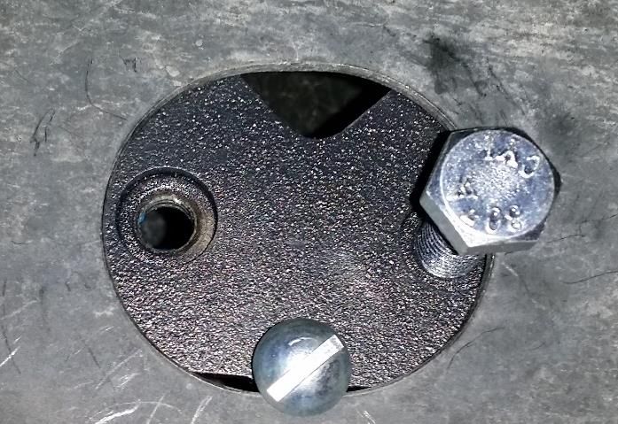
RPTR-734/230/OBA
                                                       Installation and Operation Manual
4. Application Chart
4.1.   100% Direct Bolt-On Vehicle List
RPTR-734/230/OBA is a 100% direct bolt-on aftermarket product for Ford vehicles listed in below chart; every
effort has been made to verify correct fitment on these vehicles in their factory, non-modified conditions.

   MODEL YR         MODEL           DRIVE           ENGINE               BODY                     TRIM
   2017-2020        RAPTOR           4WD              3.5L            CREW CAB**                  ALL**

       NOTE: All vehicles listed may require drilling holes for ground wires and installing switches, based on
       preference of installed switch locations and wire grounding points.

4.2.   **Excluded Vehicles

       RPTR-734/230/OBA is NOT compatible with following FORD vehicles:

       4.2.1. Super Cab or Standard Cab models

4.3.   Aftermarket Product Compatibility

       NOTE: Before installing this product on a vehicle with any aftermarket parts attached in regions shown in
       section 5.1, thoroughly review this manual to verify necessary mounting points and overall space exists.
       At discretion of end-user/installer, included Brackets/components may require modifications to attach to
       vehicles with aftermarket parts; THIS VOIDS WARRANTY OF SYSTEM.

       4.3.1. This kit has NOT been designed or tested to be compatible with leading manufacturers of
              aftermarket power truck steps, such as Amp Research Power Steps ®, which attach to inside of
              Rocker Panel.
       4.3.2. This kit has NOT been designed or tested for use with leading manufacturers of aftermarket truck
              steps, which attach to frame (i.e., nerf bars, off-road rocker panel protection, etc.).
       4.3.3. This kit has NOT been designed or tested for use with aftermarket exhaust systems.
       4.3.4. This kit has NOT been designed or tested for use with aftermarket suspension systems.

Go to Table of Contents                             PG 8/44                                   REV: A (2/13/2020)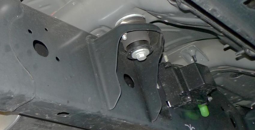
RPTR-734/230/OBA
                                                          Installation and Operation Manual
5. Installation Overview
5.1. Kit Layout and Systems Location(s)
RPTR-734/230/OBA consists of following sub-systems, located on vehicle, as follows:

  ITEM                 DESCRIPTION                              MOUNTING LOCATION                   APPROX.
                                                                                                  INSTALL TIME
    1      730 Series Large, Medium, and Small          Outside Driver side frame rail, under       2+ Hours
           Air Horns with Air Solenoid (734-KIT)        rear door.
           230 Series Large, Medium, and Small
           Air Horns with Air Solenoid (230-KIT)
    2      3 Gal. Air Tank (ALL)                        Outside Passenger frame rail, under         2+ Hours
                                                        cab, in between front/rear doors.
    3      6350RC Air Compressor (230-KIT)              Outside Passenger frame rail, under         1-2 Hours
           6450RC Air Compressor (734-KIT),             rear door.
           (OBA-KIT)

        FRONT                                                                  2

                                                                                   1
                              Figure 1 - Top View showing Kit Layout (2018 Crew Cab Shown)

Go to Table of Contents                                PG 9/44                                  REV: A (2/13/2020)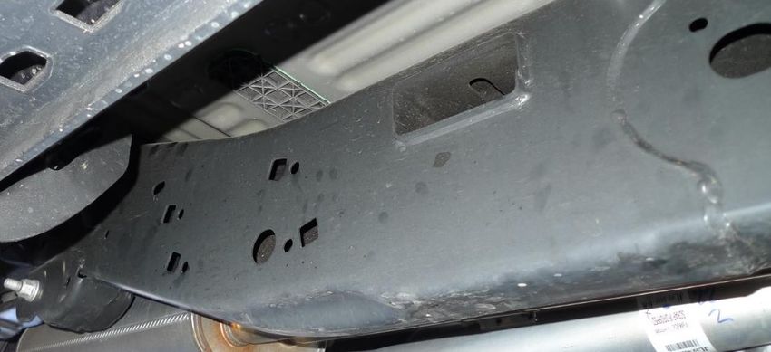
RPTR-734/230/OBA
                                                        Installation and Operation Manual
   5.2. Approximate Installation Time
   RPTR-734/230/OBA is a multi-faceted product consisting of multiple mechanical, electrical, and pneumatic
   components.

   For a typical home mechanic, auto enthusiast, or technician installing a Kleinn Bolt-On kit for first time, a
   professional installation job with setup and testing of final product, is estimated to take:

   •   6-12 Hours

   5.3. ***Quick Install Outline
   For person(s) with experience installing Kleinn bolt-on kits, RPTR-734/230/OBA can be installed in an order
   similar to below:

       1.    Route Wiring, install Relay, and install Horn Switch
       2.    Bench assemble Fittings to Air Tank
       3.    Form Tank Straps
       4.    Mount Ore-Locks and Air Horn Driver hardware to Horn Brackets
       5.    Install Air Tank bracket
       6.    Install Compressor bracket
       7.    Install Compressor & Compressor Air Filter
       8.    Install Air Tank with fittings installed
       9.    Connect air lines and wiring
       10.   Bolt in Horn brackets
       11.   Bolt on Ore bracket
       12.   Attach Air Horn Drivers to Brackets
       13.   Connect wiring and air lines
       14.   Install Trumpets into Horn Drivers & Ore mounts
       15.   Install Quick Connect Coupler and route Air Tubing
       16.   Test System and adjust, as needed

Go to Table of Contents                             PG 10/44                                    REV: A (2/13/2020)
RPTR-734/230/OBA
Installation and Operation Manual
6. List of Tools and Supplies
6.1. Standard Tool List (Required)
6.1.1. Basic mechanic’s 3/8” drive socket sets with extensions
• Inch Size Sockets (1/4” – 1” Hex)
• Metric Size Sockets (6mm – 20mm Hex)
6.1.2. Basic mechanic’s combination wrenches (box/open-end)
• Inch Size Wrenches (1/4” – 1” Hex)
• Metric Size Wrenches (6mm – 20mm Hex)
6.1.3. Basic mechanic’s screwdriver set (Philips, Flat Head)
6.1.4. Diagonal Cutter/Wire Cutter Pliers
6.1.5. Wire Strippers
6.1.6. Wire Terminal Crimpers
6.1.7. Slip-Joint Pliers
6.1.8. Utility Knife, or Utility Razor blade
6.1.9. Magnetic retrieval tool; magnetic end no larger than 3/8” in diameter
6.1.10. (Inch) Ball-end hex drivers/wrenches; long reach preferred (i.e., 6” min.)
6.2. Special Tool List (Recommended)
6.2.1. 10-100 ft.-lb. torque wrench
6.2.2. 20-150 in.-lb. torque wrench
6.2.3. Multi-Meter for 12V DC electrical systems, or equivalent
6.2.4. 12V DC Test Light, or equivalent
6.2.5. Trim Panel Tool, for removing wiring push pins
6.3. Shop Consumables List (Recommended)
6.3.1. Quality Electrical tape
6.3.2. Di-electric grease for electrical connections
6.3.3. Heat Shrink tubing for electrical connections
6.3.4. Blue Loctite (i.e., Loctite PN 242), or equivalent
6.3.5. Sand Paper, or Wire Brushes for installing ground wires
6.3.6. Extra plastic zip ties > 6” long
6.3.7. Extra NPT sealant (i.e., Kleinn Air Horn Juice, Teflon tape, etc.)
6.3.8. Touch-up paint for frame/chassis
6.3.9. Typical cleanup supplies
Go to Table of Contents PG 11/44 REV: A (2/13/2020)RPTR-734/230/OBA
Installation and Operation Manual
7. Parts List
7.1. Parts List Covers following SKU Numbers
7.1.1. RPTR-230 (i.e., 230 Train Horns)
7.1.2. RPTR-734 (i.e., 730 Train horns)
7.1.3. RPTR-OBA (i.e., On-Board Air System)
Unpackage and organize Kit across a large work area and verify all parts are included, as listed below. Contact
Kleinn support if any questions arise.
7.1.4. Review pre-packaged items (i.e., train horn box, air compressor, air tank, etc.)
7.1.5. Review Air Fittings and Tubing
7.1.6. Review Wiring and Accessories
7.1.7. Review Bolt-On Mounting Brackets
7.1.8. Review Hardware/Fasteners
7.2. Pre-Packaged Electro-Mechanical Items
NOTE: Items in this section come in their own packages and may include additional items inside package
ITEM QTY PART NUMBER DESCRIPTION PICTURE
1 1 6450RC 6450RC Compressor Kit,
734 KIT ONLY with included hardware,
OBA KIT ONLY and remote air supply
line
1 1 6350RC 6350RC Compressor Kit,
230 KIT ONLY with included hardware,
and remote air supply
line
2 1 730 730 Series Horn Kit, with
734 KIT ONLY included solenoid/valve,
and 1/2” Air Tubing, 10
ft. long
2 1 230 230 Series Horn Kit, with
230 KIT ONLY included solenoid/valve,
and 1/4” Air Tubing, 10
ft. long
Go to Table of Contents PG 12/44 REV: A (2/13/2020)RPTR-734/230/OBA
Installation and Operation Manual
7.3. Air Fittings and Related Items
ITEM QTY PART NUMBER DESCRIPTION PICTURE
3 1 6353RT Air Tank, 9-Port
4 1 52835 1/4” NPT, Drain Valve
(view location on Air Tank)
5 1 52175 1/4” NPT, 175 PSI Safety
(view location on Air Tank) Valve
6 3 50040 1/4” NPT Hex Plug
(view location on Air Tank)
7 1 51214L 1/4” NPT X 1/2”
(view location on Air Tank) Compression Fitting, 90
*734 KIT ONLY Deg Elbow
8 1 2151 1/4” NPT Pressure Switch
(view location on Air Tank)
9 1 51414L 1/4” NPT X 1/4”
(2)* (view location on Air Tank) Compression Fitting, 90
*(2) Included with 230 KIT Deg Elbow
ONLY
Go to Table of Contents PG 13/44 REV: A (2/13/2020)RPTR-734/230/OBA
Installation and Operation Manual
10 1 25014 1/4” Air Tubing, 10 ft.
long
11 1 1302 Quick Connect Air
Coupler Kit, with
relocation bracket
12 1 INF-1 Inflator Kit, with Air Hose
and Bag
13 1 KLEINN AIR HORN JUICE Thread Sealant for NPT
Fittings
Go to Table of Contents PG 14/44 REV: A (2/13/2020)RPTR-734/230/OBA
Installation and Operation Manual
7.4. Electrical Small Components and Related Items
ITEM QTY PART NUMBER DESCRIPTION PICTURE
14 1 320 Terminator – Nickel
Plated Remote Horn
Button
15 1 WIRE KIT Full Wire Kit, with
electrical connectors and
zip ties
16 1 ¼” WIRE LOOM, 20 ft. Long 1/4” Wire loom for
electrical routing
17 1 1/8” WIRE LOOM, 10 ft. Long 1/8” wire loom for
electrical routing
Go to Table of Contents PG 15/44 REV: A (2/13/2020)RPTR-734/230/OBA
Installation and Operation Manual
7.5. Bolt-On Mounting Brackets & Special Hardware
ITEM QTY PART NUMBER DESCRIPTION PICTURE
18 1 RAPTOR-101 COMPRESSOR BRACKET
(Go to Install Section)
19 1 RAPTOR-201 TANK BRACKET
(Go to Install Section)
20 2 RAPTOR-202 AIR TANK STRAP
(Go to Install Section)
21 2 RAPTOR-203 NUT PLATE
(Go to Install Section)
22 1 RAPTOR-206 SKID PLATE
(Go to Install Section)
23 1 RAPTOR-301 MAIN HORN BRACKET
(Go to Install Section)
24 1 RAPTOR-302 MEDIUM HORN BRACKET
(Go to Install Section)
25 1 RAPTOR-303 LARGE HORN ORE
(Go to Install Section) MOUNT BRACKET
Go to Table of Contents PG 16/44 REV: A (2/13/2020)RPTR-734/230/OBA
Installation and Operation Manual
7.6. Hardware/Fasteners
NOTE: Pictures only indicative, not to scale and may not represent exact item
ITEM QTY. PART DESCRIPTION WHERE USED
PICTURE
NUMBER/SIZE
H1 1 5/16" ID X 1.25” FLAT WASHER, HORN BRACKET (1)
OD FENDER, ZINC-
PLATED
H2 7 5/16" X .88” OD FLAT WASHER, HORN BRACKET (5)
USS, ZINC-PLATED TANK BRACKET (2)
H3 20 5/16" ID X 0.69” FLAT WASHER, HORN DRIVERS (6)
OD SAE, ZINC-PLATED HORN BRACKET (8)
TANK BRACKET (3)
COMPRESSOR BRACKET (3)
H4 10 1/4" ID X 0.63” FLAT WASHER, TANK STRAPS (4)
OD SAE, ZINC-PLATED ORE LOCK MOUNTS (4)
SKID PLATE (2)
H5 16 5/16"-18 HEX NUT, GRADE HORN DRIVERS (6)
2, ZINC-PLATED HORN BRACKET (8)
TANK BRACKET (2)
H6 4 1/4"-20 HEX NUT, GRADE ORE LOCK MOUNTS (4)
2, ZINC-PLATED
H7 20 5/16" SPLIT LOCK HORN DRIVERS (6)
WASHER, ZINC- HORN BRACKET (8)
PLATED TANK BRACKET (3)
COMPRESSOR BRACKET (3)
H8 10 1/4" SPLIT LOCK ORE LOCK MOUNTS (4)
WASHER, ZINC- TANK STRAPS (4)
PLATED SKID PLATE (2)
H9 4 1/4"-20 X 1" SOCKET HEAD CAP TANK STRAPS (4)
LONG SCREW, ZINC-
PLATED
H10 2 1/4”-20 X 0.75” PAN HEAD NUT PLATE (2)
LONG PHILLIPS SCREW,
ZINC-PLATED
Go to Table of Contents PG 17/44 REV: A (2/13/2020)RPTR-734/230/OBA
Installation and Operation Manual
H11 4 5/16"-18 X 1" HEX BOLT, GRADE COMPRESSOR BRACKET (2)
LONG 2, ZINC-PLATED TANK BRACKET (2)
H12 6 5/16"-18 X 0.75" KNURLED TANK BRACKET (2)
LONG CARRIAGE BOLT, HORN BRACKET (4)
GRADE 2, ZINC-
PLATED
H13 6 5/16"-18 X 1.25" SQUARE NECK HORN DRIVERS (6)
LONG BOLT, GRADE 2,
ZINC-PLATED
H14 4 1/4"-20 X 1" SQUARE NECK ORE LOCK MOUNTS (4)
LONG BOLT, GRADE 2,
ZINC-PLATED
H15 2 9” LONG RUBBER TRIM TANK BRACKET (2)
(“NARROW U”)
H16 2 9” LONG RUBBER TRIM TANK STRAPS (2)
(“WIDE C”)
H17 1 5/16"-18 X 1" KNURLED HORN BRACKET (1)
LONG CARRIAGE BOLT,
GRADE 2, ZINC-
PLATED
H18 2 5/16"-18 X .75" SQUARE NECK HORN BRACKET (2)
LONG BOLT, GRADE 2,
ZINC-PLATED
H19 4** M5 X 0.8 HEX NUT, CLASS 4, COMPRESSOR (4)
BLACK OXIDE **INSIDE COMPRESSOR
BOX
H20 8** M5 ID X 10 OD FLAT WASHER, COMPRESSOR (8)
DIN, BLACK OXIDE **INSIDE COMPRESSOR
BOX
H21 4** M5 SPLIT LOCK COMPRESSOR (4)
WASHER, BLACK **INSIDE COMPRESSOR
OXIDE BOX
Go to Table of Contents PG 18/44 REV: A (2/13/2020)RPTR-734/230/OBA
Installation and Operation Manual
H22 4** M5 X 40 HEX BOLT, CLASS COMPRESSOR (4)
4.6, BLACK OXIDE **INSIDE COMPRESSOR
BOX
H23 2 1/4”-20 X .75” HEX BOLT, GRADE SKID PLATE (2)
LONG 2, ZINC-PLATED
H24 1 M8 X 1.25 NO-SLIP, CLIP-ON HORN BRACKET (1)
BARREL NUT, ZINC-
PLATED
H25 1** M8 X 1.25 HEX BOLT, CLASS HORN BRACKET (1)
4.6, ZINC-PLATED **INSIDE HORN BOX - ORE
LOCK BAG
H26 1** M8 X 16 FLAT WASHER, HORN BRACKET (1)
DIN, ZINC-PLATED **INSIDE HORN BOX - ORE
LOCK BAG
H27 1** M8 SPLIT LOCK HORN BRACKET (1)
WASHER, ZINC- **INSIDE HORN BOX - ORE
PLATED LOCK BAG
End of Section
Go to Table of Contents PG 19/44 REV: A (2/13/2020)RPTR-734/230/OBA
Installation and Operation Manual
8. On-Vehicle Electrical Installation
CAUTION: Follow all recommended safety precautions for working on vehicle’s electrical system; consult vehicle
owner’s manual for further instruction.
8.1. Relay and Fuse Diagram for Air Horn System
Figure 2 - Suggested Ignition Relay Diagram for 730/230/OBA
Go to Table of Contents PG 20/44 REV: A (2/13/2020)RPTR-734/230/OBA
Installation and Operation Manual
8.2. Suggested Wire Routing for Air Horn System
Figure 3 - Suggested Wire Routing for Horn, Air Compressor, and Pressure Switch
8.3. Disconnect Vehicle Battery(s)
8.3.1. Use special care if vehicle is equipped with any Auxiliary Auto Stop Battery. Consult Owner’s Manual.
8.4. Connect Wiring to Relay(s) and Fuse(s), then Attach to Vehicle
8.4.1. Find a suitable location for supplied relay(s) and fuse(s). Shown below is an example location under
hood next to battery and near grounding block. Use supplied self-tapping screws, as necessary.
Fuse Relay
FRONT
Ground
Block
Relay and Fuse Installation Example (2016 Tundra Shown)
Go to Table of Contents PG 21/44 REV: A (2/13/2020)RPTR-734/230/OBA
Installation and Operation Manual
8.4.2. Insert all wiring into included wire loom and ensure loom is away from all sharp edges, hot vehicle parts
(i.e., exhaust, engine, radiator), and fasten securely to vehicle using zip ties, or equivalent.
NOTE: Do not cut wires to length until 100% sure of length required for final connections.
8.4.3. Install supplied fuse holder on end of power wire by cutting the loop in fuse holder and connecting
supplied Ring terminal to one end and Butt connector on other end.
CAUTION: Do not install 30-amp fuse until all electrical connections are final.
8.4.4. Find a suitable location for horn push-button (i.e., in dash, center console, etc.); verify location has 1”+ of
clearance behind for terminals. Mark location for drilling.
Terminator Horn Button Install Example OEM Upfitter Switch Example
NOTE: FOR VEHICLES WITH FACTORY UPFITTER SWITCHES:
If vehicle is equipped with factory upfitter (i.e., auxiliary) switches, they may be used for Kleinn Air Horn
kit; consult Owner’s Manual, or dealership for further instructions on wiring and programming required.
8.4.5. Drill a 3/4” hole at location. Route horn button wires to hole then slide push-button retaining nut over
wires and connect per wiring diagram. Install push-button into hole and tighten retaining nut securely on
backside.
8.5. Connect partial length of wiring to Air Horn Solenoid(s)
8.5.1. Vehicle space constraints may make it difficult to connect Air Horn Solenoid(s) in-vehicle. Review install
location for available space; if desired, cut and connect a section of wiring to Solenoid(s) before installing
into vehicle, then perform final connection once Air Horn assembly is installed.
NOTE: If connecting upgraded Solenoid Kit (BlasterMaster Pro), see instructions contained in package
8.6. Connect partial length of wiring to Pressure Switch
8.6.1. Vehicle space constraints may make it difficult to connect Air Tank Pressure Switch in-vehicle. Review
install location for available space; if desired, cut and connect a section of wiring to Pressure Switch before
installing Air Tank into vehicle, then perform final connection once Air Tank is installed.
End of Section
Go to Table of Contents PG 22/44 REV: A (2/13/2020)RPTR-734/230/OBA
Installation and Operation Manual
9. Bench Assembly Steps
Complete following steps off vehicle to facilitate final installation.
NOTE: ALL HARDWARE WILL BE SPECIFIED IN INSTRUCTIONS USING ITEM NO.’S FOUND IN PARTS LIST. See Parts
List. Assemble ALL fasteners clean and dry using proper socket and box-end wrench. (Not including Air fittings)
9.1. Disassemble 730/230 Horn Kit from Box
9.1.1. Unpackage and fully disassemble included train horn kit; train horns must be separated to allow individual
installation to Bracketry.
Click Here to View Instructions on Kleinn.com
9.2. Assemble Air Tank Fittings to Air Tank
9.2.1. Apply two small drops of Kleinn Air Horn Juice to each male pipe thread.
9.2.2. Attach air fittings to tank, per below illustration, Click Here to View Fittings List
To Air Coupler To Air Horn
FRONT
9 8 Compressor Inlet
7/9* 6
5
4
6
FRONT
Figure 4 - Air Fittings installed in Air Tank with locations
9.2.3. Hand-tighten each fitting, then further tighten each 1/4-1/2 turn using proper sized box-end wrench;
adjust as necessary to match fitting orientation shown in above figure.
Go to Table of Contents PG 23/44 REV: A (2/13/2020)RPTR-734/230/OBA
Installation and Operation Manual
9.3. Attach Air Tank Straps to Tank Bracket
NOTE: Space constraints with Tank Bracket installed on vehicle makes accessing top Air Tank Strap
mounting bolts difficult to achieve; therefore, it is recommended to follow below procedure. If long reach
(i.e., minimum 6 inch) ball-nose hex drivers are available, Straps may be fully installed in vehicle.
9.3.1. Temporarily place Air Tank inside Tank Bracket, then attach both RAPTOR-202 Air Tank Straps to upper
holes on RAPTOR-201, using hardware (2) #4, #8, #9., as shown in Figure 5 below.
9.3.2. To form straps around tank, ensure top bolts are hand tight, then grasp each strap and bend it around
tank, as shown below. Once strap is formed, torque top bolt to 37 in-lbs and remove tank from Bracket,
as shown in Figure 5 below.
9.3.3. Attach (2) Rubber strips #16 to RAPTOR-202 parts, as shown with green arrows in Figure 5 below.
NOTE: Straps should be aligned vertically, with bottom holes on RAPTOR-201 & RAPTOR-202 lining up.
1. Attach Straps 2. Form Straps
5. Attach
Rubber
4. Torque bolts
and remove Tank
3. Align Straps
with bottom holes
3 Holes this side
Figure 5 - RAPTOR-202 Tank Straps Formed and Attached (Shown without Air Tank and mis-aligned)
Go to Table of Contents PG 24/44 REV: A (2/13/2020)RPTR-734/230/OBA
Installation and Operation Manual
9.4. Ore-Lock to Brackets Installation
NOTE: Ore Locks are included ONLY with 734 KIT (i.e., 730 Air Horns)
9.4.1. Using hardware #3, #5, #7, & #18, secure RAPTOR-303 to RAPTOR-301. Hand tighten fasteners only at
locations shown circled in yellow in Figure 6 below.
Attach bolts now
Shown for
reference only
Figure 6 - RAPTOR-303 attached to RAPTOR-301
9.4.2. Remove Ore Locks from Air Horn package and discard their included hardware. Attach Ore Locks onto
Medium and Large Horn Bracket using hardware #4, #6, #8, and #14, as shown circled in Figure 7 below.
Ore Lock
Shown for reference only Attach bolts now
Figure 7 - Ore Locks attached to RAPTOR-301 and RAPTOR-303 (734 KIT ONLY)
Go to Table of Contents PG 25/44 REV: A (2/13/2020)RPTR-734/230/OBA
Installation and Operation Manual
9.5. Air Horn Driver Hardware Attachment
NOTE: Space constraints between Air Horns Brackets and vehicle frame when installed make inserting
Air Horn Driver hardware difficult to achieve; therefore, it is recommended to attach hardware before
installing Brackets on frame.
9.5.1. Loosely attach hardware #3, #5, #7, & #13, to RAPTOR-301 and RAPTOR-302 Horn Brackets in locations
shown circled in Figure 8 below. Square Neck Bolt should be inserted on backside of Brackets, with
remaining hardware above Brackets.
Figure 8 - RAPTOR-301, 302, 303 with Air Horn Driver Hardware circled (shown on frame)
Go to Table of Contents PG 26/44 REV: A (2/13/2020)RPTR-734/230/OBA
Installation and Operation Manual
10. On-Vehicle Mechanical Assembly Steps
Complete following steps on vehicle.
Raise vehicle off ground using appropriate vehicle lift, ramps, or jack stands, to improve ease of installation.
DANGER: Follow all safety precautions for raising vehicle and working beneath it; consult vehicle owner’s
manual.
NOTE: Any parts permanently removed from vehicle should not be discarded; store for future use if Kit is
removed. Pre-soak ALL OEM vehicle fasteners with WD-40, PB-Blaster, etc. before attempting to loosen
fasteners! This is especially critical on blind, threaded holes, where nuts/threads are not easily replaced.
CAUTION: All components installed in this kit should have a minimum of 1/4” of clearance from vehicle body.
10.1. Nut Plate Installation
10.1.1. Locate two large oval holes on passenger side frame rail, under front door, as shown in Figure 9 below.
Body Mount
FRONT
Figure 9 - Frame Hole Locations for RAPTOR-203; below front door
10.1.2. Locate two holes on same section of frame, under rear door, as shown in Figure 10 below.
Oval hole
FRONT
Crossmember
Left Bolt Holes
Figure 10 - Passenger Frame Rail Hole Locations, under rear door
Go to Table of Contents PG 27/44 REV: A (2/13/2020)RPTR-734/230/OBA
Installation and Operation Manual
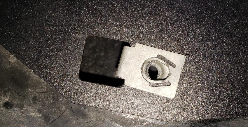
10.1.3. Thread hardware #10 into RAPTOR-203, so Nut Plate can be held by screw. Do not thread bolt in fully.
UP
Figure 11 - RAPTOR-203 with #10 Inserted
10.1.4. Install Nut Plates into frame holes circled in Figure 9 above. Use care not to drop Nut Plate inside frame.
Follow Figure 12 below on insertion method.
1. Insert and Twist 2. Center in hole
3. Tighten #10
Figure 12 - RAPTOR-203 Insertion Method and Tightened to Frame.
10.1.5. Once Nut Plate is inside hole and rotated as shown above, firmly tighten #10 screw to frame. Screw will
be on bottom edge of frame. Ensure Nut Plate is centered within frame hole vertically and horizontally.
10.1.6. Repeat above steps for second Nut Plate.
Go to Table of Contents PG 28/44 REV: A (2/13/2020)RPTR-734/230/OBA
Installation and Operation Manual
10.2. Knurled Carriage Bolt Installation (“Knurled Bolt Stack-Up”)
10.2.1. With specified washer installed on Knurled Carriage Bolt, slide bolt through frame, and hold in position.
10.2.2. Use small magnetic tool to secure end of bolt and bring through specified holes shown in Figure 13.
Attach Magnetic retrieval Insert Bolt & Washer
tool to end of bolt, and through nearest
pull bolt through square frame hole.
Figure 13 - Knurled Bolt Installation (Common throughout)
10.2.3. All Knurled Carriage Bolts will be attached to frame and Brackets in order shown in Figure 14 below.
NOTE: Knurled Carriage Bolts will press fit into Bracket holes during final tightening; if necessary to loosen
bolts for re-positioning, first loosen nut until flush with end of bolt and hit end of bolt with hammer to
punch bolt slightly out of hole.
Final torque:
12 2 Frame Bracket 3 7 5
75-88 in-lbs
Figure 14 - Knurled Carriage Bolt “Stack-up” (Common throughout)
Go to Table of Contents PG 29/44 REV: A (2/13/2020)RPTR-734/230/OBA
Installation and Operation Manual
10.3. Tank Bracket Installation and Temporary Tightening
10.3.1. Install RAPTOR-201 onto frame using 10.3.2. Install hardware #3, #7, & #11 into left hole
hardware #2, #3, #5, #7, and #12 in left side on right side of RAPTOR-201, as circled
holes, as shown Figure 15 below. Hand below. Ensure right hole is lined up and
tighten only, to allow later adjustment. tighten firmly, as shown in Figure 16 below.
Torque to
75-88 in-lbs
RAPTOR-101
Mount Hole
#10 screw
Figure 15 - RAPTOR-201 Hardware Location (left side) Figure 16 - RAPTOR-201 Hardware Location (right side)
10.3.3. Verify RAPTOR-101 hole is lined up, then remove #10 screw as shown circled in Figure 16 above. If
necessary, thread another bolt into RAPTOR-101 hole to ensure correct alignment.
FRONT
Figure 17 - RAPTOR-201 Bolted to Frame (Compressor Bracket also shown attached)
Go to Table of Contents PG 30/44 REV: A (2/13/2020)RPTR-734/230/OBA
Installation and Operation Manual
10.4. Compressor Bracket Installation and Final Tightening
10.4.1. Mount RAPTOR-101 on top of RAPTOR-201, using hardware #3, #7, #11 throughout.
Figure 18 - RAPTOR-101 Mounted on top of RAPTOR-201
10.4.2. Remove #10 screw from right side of Compressor Bracket.
10.4.3. Position both Tank Bracket and Compressor Bracket toward bottom of bolt holes (i.e., provides
maximum Air Tank and Compressor clearance to vehicle body); ensure Brackets are level/parallel to
vehicle frame.
10.4.4. Final torque all Tank Bracket and Compressor Bracket mounting hardware, as shown in figures above.
Go to Table of Contents PG 31/44 REV: A (2/13/2020)RPTR-734/230/OBA
Installation and Operation Manual
10.5. Attach Compressor to Bracket
10.5.1. Using hardware #19, #20, #21, & #22 mount Compressor to RAPTOR-101 as shown in Figure 19 & 20
below.
Leader Hose location FRONT
Air Filter Inlet
Figure 19 - Compressor Mounted on RAPTOR-101
10.5.2. Ensure Compressor is oriented properly, with output “leader” hose facing forward, as shown above.
(Top Down Order)
Nut (#19)
Lock Washer (#21)
Washer (#20)
Comp. + Bracket
Washer (#20)
Bolt (#22)
Figure 20 – Standard Air Compressor fasteners “Stack-Up”
Go to Table of Contents PG 32/44 REV: A (2/13/2020)RPTR-734/230/OBA
Installation and Operation Manual
Leader Hose location
Zip Tie installed
Figure 21 - Compressor installed. Leader Hose Zip-tied to Compressor end plate hole
10.5.3. Torque Compressor Hardware to 18 in-lbs.
10.5.4. Install Air Compressor filter to Compressor, or if preferred to mount filter remotely, attach threaded
barb to front of Compressor, as shown in Figure 22 below.
NOTE: See remote air filter installation instructions included within Air Compressor package. Some
examples of remote locations include under body, in bed, under hood, etc. If preferred to install Air
Compressor Filter Relocation kit, do so before Air tank is installed.
10.5.5. Attach wiring to Compressor and Air Tank Pressure switch, as per wiring diagram shown in Figure 2.
10.5.6. Install wiring loom provided to protect wiring and securely attach all wires to vehicle using zip ties.
Remote Filter
Air Filter Inlet
Figure 22 - Air Compressor Filter Remote Tubing shown attached
Go to Table of Contents PG 33/44 REV: A (2/13/2020)RPTR-734/230/OBA
Installation and Operation Manual
10.6. Air Tank Installation
10.6.1. Attach Rubber strip #15 (Thin “U”) to Tank Bracket, shown with red arrows in Figure 23 below.
Figure 23 - Rubber Strips Attached to Tank Bracket and Tank Straps
10.6.2. Orient Air Tank and secure both RAPTOR-202 to bottom holes using hardware #4, #8, & #9, as shown in
Figure 24 below. Final torque to 37 in-lbs.
Leader Inlet
Drain Valve
should almost
FRONT
touch Strap
***Drain must be
vertical/plumb
Figure 24 - Air Tank Final Installed
10.6.3. Connect Compressor leader hose to open port in Air Tank and tighten. Apply two small drops of Kleinn
Air Horn Juice to each male pipe thread.
Go to Table of Contents PG 34/44 REV: A (2/13/2020)RPTR-734/230/OBA
Installation and Operation Manual
10.7. Drain Valve Skid Plate Installation
NOTE: If desired, Skid Plate may be left off. Its purpose is to minimize potential Air Tank Drain Valve
damage from aggregates and projectiles coming from front and rear tires. If elected to install, it may be
necessary to remove each time Air Tank is drained.
10.7.1. Locate two holes on RAPTOR-201, near Air Tank drain fitting, as shown in Figure 25 below.
Figure 25 - RAPTOR-206 Lined Up with RAPTOR-201
10.7.2. Using #4, #8, #23, install RAPTOR-206 and fully tighten hardware, as shown in Figure 26 below.
Figure 26 - RAPTOR-206 Installed on Tank Bracket
Go to Table of Contents PG 35/44 REV: A (2/13/2020)RPTR-734/230/OBA
Installation and Operation Manual
10.8. Connect Remote Quick Connect Kit to Vehicle
10.8.1. Route and attach Quick Connect Coupler Kit to vehicle, as desired using attachment bracket and self-
drilling fasteners, supplied in Coupler package
10.8.2. Use supplied 1/4“ tubing and attach to port shown in Air Tank Fittings figures above.
Some optional locations include under hood, near grill, behind bumper, in bed rail, etc.
Figure 27 – Example of Air Coupler Mounted To Bumper
Go to Table of Contents PG 36/44 REV: A (2/13/2020)RPTR-734/230/OBA
Installation and Operation Manual
10.9. Main Horn Bracket Installation
NOTE: loosely attach all hardware for Horn Drivers before installing brackets, as shown above. If your
vehicle is equipped with Electronic Parking Brakes, skip all references to below Parking Brake Cables and
use hardware #24, #25, #26, & #27 in place of OE Bolt and Frame Clip.
Figure 28 - Driver's Side Frame Rail under rear door
10.9.1. Locate section of frame for Horn Bracket installation. Remove two bolts shown circled in Figure 28
above; do not discard hardware. Pull brake cables away from frame to facilitate bracket installation.
Yellow #2 Red #3
Green #1
Figure 29 – Main Horn Brackets Mounting Holes in Frame
Go to Table of Contents PG 37/44 REV: A (2/13/2020)RPTR-734/230/OBA
Installation and Operation Manual
10.9.2. Locate all mounting holes shown circled in Figure 29 above.
10.9.3. Remove factory frame clip behind Parking Cable Bracket, as shown circled (Green #1) in Figure 29 above.
10.9.4. Lift RAPTOR-301 into place, as shown in Figure 30 below.
Green #1 Yellow #2 Red #3
Figure 30 - View of Frame with Frame Clip location circled; RAPTOR-301, 302, 303 shown installed
10.9.5. Slide factory frame clip over original location, clamping RAPTOR-301 to frame, as shown below.
Figure 31 - Factory Frame Clip Reinserted into RAPTOR-301
10.9.6. Reinstall factory Parking Brake Cable Bracket using factory bolt.
10.9.7. Secure RAPTOR-301 to frame using hardware #2, #3, #5, #7, and #12. Knurled bolt “Stack-up” applies.
Go to Table of Contents PG 38/44 REV: A (2/13/2020)RPTR-734/230/OBA
Installation and Operation Manual
Red #3
Figure 32 - Reinstalling brake bracket over RAPTOR-301
10.9.8. Secure RAPTOR-303 over RAPTOR-301 to vehicle frame using hardware #2, #3, #5, #7, & #17, as shown
circled (Red #3) in Figure 32 above.
10.9.9. Final tighten all fasteners in this section.
10.10. Medium Horn Bracket Installation.
10.10.1. Locate 2 holes in frame shown in Figure 29 below.
Red Red Rear spring bolt
Yellow Yellow
Figure 33 - Medium Horn Bracket Mounting Points
10.10.2. Attach RAPTOR-302 to vehicle frame using hardware #2, #3, #5, #7, & #12 for mounting point shown
circled red in Figure 33 above.
10.10.3. For mounting point circled yellow, use hardware #1, #3, #5, #7, & #12. Knurled bolt “Stack-up” applies.
NOTE: use washer #1 BEHIND frame (i.e., normal location for #2, per “Stack-Up”)
10.10.4. Final tighten all fasteners in this section.
10.10.5. See Figure 30 above for Brackets installed in proper location and orientation.
Go to Table of Contents PG 39/44 REV: A (2/13/2020)RPTR-734/230/OBA
Installation and Operation Manual
10.11. Air Horn Driver Installation
10.11.1. Mount all Air Horn Drivers following layout shown in Figure 34 below. Mount Air Horn Drivers using
hardware #3, #5, #7, & #13. Standard Knurled bolt “Stack-up” DOES NOT apply. Hand tighten only.
NOTE: ensure arrow on primary brass Solenoid is pointing toward Air Horn Driver
FRONT
Main
Small Large Medium Solenoid
Figure 34 – Air Horn Layout (730 Horns shown with Trumpets attached); same for 734/230 Kits
Figure 35 - Air Horn Driver with Hardware Installed
Figure 36 – Air Horn Drivers Installed
(Common Throughout)
(solenoids may differ from ones shown)
Go to Table of Contents PG 40/44 REV: A (2/13/2020)RPTR-734/230/OBA
Installation and Operation Manual
10.12. Connect Air Tubing to Air Horn Driver
10.12.1. Route supplied semi-rigid plastic Air Tubing, as necessary to avoid sharp edges and high heat areas.
10.12.2. Connect Air Horn Drivers together with supplied 1/4” Air Tubing.
10.12.3. Connect Medium Driver Solenoid to proper Air Tank fitting, as shown in Fitting location figure above.
NOTE: It’s recommended to route air line through crossmember in front of Compressor, as shown below.
Figure 37 - Air Line Routing Through Frame Crossmember
10.12.4. Connect supplied wiring to Medium Horn solenoid, as per wiring diagram in Figure 2. Use supplied
wiring loom to cover all bare wires, and secure wiring to body.
10.13. Re-attach Trumpets to Air Horn Drivers
10.13.1. Re-attach Horn Trumpets to their respective Air Horn Drivers, as shown in Figure 34 above; if using Ore-
Locks, it’s necessary to first slide Trumpet throats through Ore-Locks and into Air Horn Drivers. Tighten
snugly using both hands to twist along bell end.
10.13.2. Position each Air Horn, as necessary to maintain at minimum ¼” between Trumpets and vehicle body.
Firmly tighten Air Horn mounting bolts to 75-88 in-lbs.
10.13.3. Using supplied plastic zip ties secure Air Tubing to Trumpets, as necessary to prevent abrasion.
NOTE: If parking brake cable contacts Trumpet(s), secure parking brake to Trumpet(s) using zip tie(s).
End of Section
Go to Table of Contents PG 41/44 REV: A (2/13/2020)RPTR-734/230/OBA
Installation and Operation Manual
11. Initial Testing of Kit WARNING: NEVER operate train horns with ears
close to trumpets or in an enclosed space
11.1. Reconnect Vehicle Battery(s)
without substantial hearing protection (i.e., >
Ear Plugs and Ear Muffs) for all persons closer
CAUTION: Before connecting vehicle battery(s),
than 100 feet from vehicle. Never operate train
verify all wiring is properly connected and no shorts
horns outdoors when persons are near vehicle
exists. Use of Multi-Meter, or Test Light is
recommended to check continuity of all connections. without adequate hearing protection.
11.2. Test Air Compressor 11.3.4. Briefly activate Horns by pressing Horn
11.2.1. Turn vehicle ignition to on position and Button for one (1) second; repeat three (3)
allow compressor to fill Air Tank. Initial fill times with a short rest period between
may take approximately 1.5-3 minutes; Air (i.e., 1-3 seconds)
Compressor should shut off automatically
11.3.5. Horns should sound as expected and be
once full pressure is achieved.
loud; click to listen to example 230 Kit
11.2.2. If compressor runs excessively (i.e., 5
minutes or more), disconnect electrical 11.3.6. Horn sound/loudness will taper quickly as
power to Air Compressor and listen for air Air Tank loses pressure
leaks in system. Repair any problems and 11.3.7. Allow Air Compressor to refill tank, if
retest; contact Kleinn technical support if needed and activate Horns for longer
problem persists. three (3) second period to ensure Horns
11.2.3. Inspect all air line connections (i.e., Air
are functioning properly.
Tank fittings, Quick Connect fittings, Air
Horn fittings, etc.) for leaks by using a soap
and water solution sprayed directly onto 11.4. Test Quick Connect Coupler
fittings 11.4.1. Allow Air Compressor to refill tank, if
11.2.4. System must be pressurized or at least Air needed
Compressor running
11.4.2. Attach supplied INF-1 inflator kit to Quick
11.2.5. If an air leak is found:
11.2.6. Safely release air pressure from system Connect Coupler and verify adequate air
(i.e., slowly open drain valve) pressure is available
11.2.7. Disassemble leaky connection, re-seal and 11.4.3. Test fill tires on vehicle, bicycle, etc.
reinstall fittings as needed 11.4.4. Use Air Blow Gun
11.4.5. Use Air Impact Gun
11.3. Test Train Horns
11.3.1. Allow Air Compressor to run and shut-off End of Section
automatically (i.e., Air Tank is full)
11.3.2. Verify all tubing and electrical wire is
securely fastened to vehicle, brackets, or
kit parts; if necessary, use extra zip ties to
hold tubing and wire in place
11.3.3. Ensure all nearby persons have adequate
hearing protection and provide courtesy
warning to neighbors or others in vicinity
Go to Table of Contents PG 42/44 REV: A (2/13/2020)RPTR-734/230/OBA
Installation and Operation Manual
12. General Operation of Kit 13.1. Yearly, or every 12000 miles verify all
mounting fasteners are properly torqued;
12.1. Compressor Operation applying witness marks across fasteners and
mounting parts is good practice to quickly
WARNING: Never operate Air Compressor above ensure fasteners have not moved.
its MAXIMUM PRESSURE RATING (see label on 13.2. Yearly, or every 12000 miles remove all road
body). Operation exceeding maximum pressure grime and mud from mounting brackets and
will damage Air Compressor and may result in kit parts using clean water from a garden
Dangerous Air System failure. hose; pay special attention to corners where
dirt may collect. Touch up all paint chips
12.1.1. Air compressor is equipped with an using automotive grade enamel in either
automatic thermal overload protection spray, or brush form.
circuit, designed to protect air compressor
from overheating and causing permanent NOTE: High-pressure washers may damage part
damage. finishes and must be used with care. Do this
12.1.2. Automatic thermal overload protector will more frequently if traveling regularly off-
automatically reset after 30 minutes. road, or in winter climates where road salts
12.1.3. To prevent discharge of vehicle’s battery are used.
and for best performance, keep vehicle’s
engine running while using air compressor 13.3. Yearly, or every 12000 miles check electrical
for any prolonged use (i.e., filling tires, and air fitting connections and wires for
using air tools, etc.). abrasion, corrosion, or other damage.
Replace damaged components.
12.2. Horn Operation NOTE: if system runs continuously or turns on
12.2.1. Allow Air Compressor to run until it shuts unexpectedly, leaks or intermittent
off automatically (i.e., Air Tank is full), or electrical connection may be present.
for at least one minute in between horn
activations. 13.4. Monthly, or every 10 hours of compressor
12.2.2. Press Horn Button to activate Horns run time, drain moisture from air tank using
drain valve installed at bottom of tank.
12.2.3. Horn sound/loudness will taper quickly as
Air Tank loses pressure. WARNING: Failure to regularly drain air tank may
12.2.4. Horns should sound for 3-7 seconds result in corrosion inside tank and possible
depending on kit and tank size failure in tank or air lines, which can suddenly
WARNING: NEVER operate train horns with ears release air pressure causing injury to nearby
people.
close to trumpets or in an enclosed space
without substantial hearing protection (i.e., > 13.5. Yearly, or every 12000 miles clean, or
Ear Plugs and Ear Muffs) for all persons closer replace air compressor air filter element.
than 100 feet from vehicle. Never operate train Replacement frequency depends on
horns outdoors when persons are near vehicle operating frequency and conditions of
without adequate hearing protection. operating environment (i.e., daily use of air
compressor in dusty, or wet environment
requires more frequent filter change). Order
13. Routine Maintenance replacement filters at Kleinn.com.
Perform following steps at least once during
recommended intervals. NOTE: Never lubricate or add any liquids to the
included oil-less air compressor
Go to Table of Contents PG 43/44 REV: A (2/13/2020)RPTR-734/230/OBA
Installation and Operation Manual
14. Warranty Information
Thank you for purchasing this RPTR-734/230/OBA. Shall you experience any unexpected problems during
installation, or have problems with any part at any time please contact Kleinn support.
© Kleinn Air Horns 2020, All rights reserved.
PO Box 91278 Tucson, AZ 85752
Phone: (520) 579-1531
Web: www.Kleinn.com
Go to Table of Contents PG 44/44 REV: A (2/13/2020)You can also read