INSTRUCTION MANUAL TW 280TVGTR WOOD CHIPPER - timberwolf-uk.com - Almovi
←
→
Page content transcription
If your browser does not render page correctly, please read the page content below

TW 280TVGTR WOOD CHIPPER
  INSTRUCTION MANUAL
      (ORIGINAL INSTRUCTIONS)

     timberwolf-uk.com
© Copyright Timberwolf Ltd 2021
The content of this publication may not be copied, reproduced, republished, posted, broadcast, transmitted
           or used in any way in any medium without the written permission of Timberwolf Ltd.
CONTENTS 1 / 73
TW 280TVGTR
Section Page No.
INTRODUCTION 2
PARTS LOCATOR DIAGRAMS 3
SAFE WORKING 5
Operator’s Personal Protective Equipment (PPE) 5
Basic Woodchipping Safety 5
General Safety Matters 5
Noise Test 6
STORAGE 7
Storing the Chipper 7
OPERATING INSTRUCTIONS 8
Recommissioning after Storage 8
Vibration Data 8
Delivery 9
Manual Controls 9
Auto Controls 9
Emergency Stopping 9
Engine Controls 10
Crawler Track Controls 10
Daily Checks Before Starting 11
Before Using the Chipper 11
Starting the Engine 11
Controlling the Engine Speed 11
Stopping the Engine 11
Discharge Controls 12
Starting to Chip 12
Chipping 12
Blockages 12
Blade Wear 13
Hydraulic Oil Level and Temperature Indicator 13
Fuel Level Indicator 13
Refuelling 13
Winch Operation 13
Troubleshooting 14
SERVICE INSTRUCTIONS 15
Service Schedule 15
Safe Maintenance 16
Safe Lifting and Securing Down of the Chipper 16
Spares 16
Battery Removal and Maintenance 16
Check Fittings 16
Hazardous Materials and End of Machine Life 17
Battery Safety Information 18
Change Blades 19
Tension Drive Belts 20
Tension Hydraulic Pump Belt 20
Grease the Discharge Flange 20
Grease the Roller Spline and Rotor Bearings 21
Grease the Roller Box Slides 21
Engine Servicing 21
Check Hoses 21
Change Hydraulic Oil and Filter 22
Track Base Maintenance 22
Replacement of Oil in the Track Drive Unit 22
Draining the Oil in the Track Drive Unit 22
Reduction Unit Oil Types 22
Checking the Rubber Tracks 23
Support Stand 23
Checking Track Tension 23
Track Loosening/Tightening Procedures 24
Removing the Rubber Tracks 24
Installing the Rubber Tracks 25
Checking Sprocket Wear 25
WARRANTY STATEMENT 26
DECLARATION OF CONFORMITY 27
IDENTIFICATION PLATE 28
DECALS 29
ELECTRICAL PARTS LOCATOR 31
CIRCUIT DIAGRAMS 32
HYDRAULIC LAYOUT 35
VBELT TENSIONING TABLE 36
WARRANTY SERVICE CHECK RECORD 37
SERVICE RECORD 38
PARTS LISTS 39
C1900176 08.07.2021 Rev: 4.0
INTRODUCTION 2 / 73
TW 280TVGTR
Thank you for choosing Timberwolf. Timberwolf chippers are designed to give safe
and dependable service if operated according to the instructions.
IMPORTANT HEALTH AND SAFETY INFORMATION
Before using your new chipper, please take time to read this manual. Failure to do
so could result in:
personal injury
equipment damage CAUTION or WARNING
damage to property BE AWARE OF THIS SYMBOL
3rd party injuries AND WHERE SHOWN,
This manual covers the operation and maintenance of the Timberwolf TW 280TVGTR CAREFULLY FOLLOW THE
and optional Timberwolf Safety Plus Kit. All information in this manual is based on INSTRUCTIONS.
the latest product information available at the time of purchase.
All the information you need to operate the machine safely and effectively is THIS SYMBOL INDICATES
contained within pages 3 to 12. Ensure that all operators are properly trained for IMPORTANT SAFETY
operating this machine, especially in safe working practices.
MESSAGES IN THIS MANUAL.
Timberwolf's policy of regularly reviewing and improving their products may involve WHEN YOU SEE THIS
major or minor changes to the chippers or their accessories. Timberwolf reserves SYMBOL, BE ALERT TO THE
the right to make changes at any time without notice and without incurring any POSSIBILITY OF INJURY TO
obligation.
YOURSELF OR OTHERS AND
Due to improvements in design and performance during production there may be, CAREFULLY READ THE
in some cases, minor discrepancies between the actual chipper and the text in this MESSAGE THAT FOLLOWS.
manual.
The manual should be considered an important part of the machine and should
remain with it if the machine is resold.
ALWAYS FOLLOW SAFE
OPERATING AND
MAINTENANCE PRACTICES
PURPOSE
The Timberwolf TW 280TVGTR is designed to chip solid wood material up to 210mm
in diameter and capable of chipping over 6.5 tonnes of brushwood per hour.
DIMENSIONS SPECIFICATION
Engine type:
Kubota 4cylinder turbo diesel
2455mm with tracks down, 1765mm with discharge removed,
Serial No. Location.
The serial number Maximum power:
can be found on
the identification 33kW (45hp)
plate located on Cooling method:
the chassis beam.
Water cooled
2850mm with tracks extended
Overall weight:
2089kg (2155kg with winch)
Starting method:
Electric
Roller feed:
Twin series hydraulic motors
mm ith ) Maximum diameter material:
80 w ed
14 mmtend 210mm (8 1⁄4")
10 ex
(2a0cks Fuel capacity:
tr 36 litres
Hydraulic oil capacity:
50 litres
2880m Material processing capacity:
m
3665m (with tray Up to 6.5 tonnes/hr
m (wit an
h tray d step fold Fuel type:
and st e
ep do d) Diesel
wn)
C1900176 08.07.2021 Rev: 4.0
PARTS LOCATOR 3 / 73
TW 280TVGTR
DISCHARGE TUBE DISCHARGE
INCLINOMETER BUCKET
DISCHARGE
EMERGENCY ADJUSTMENT CONTROL
PUSH STICK STOP
FUNNEL
FEED TRAY
LIFTING EYE EXHAUST
ROLLER BOX
GUARD AIR INTAKE THROTTLE LEVER
SAFETY BAR
ENGINE BAY ENGINE STOP
SIDE PANELS SWITCH
CONTROL BOX
(each side) DRIVING
CONTROL
PANEL
MANUAL CANNISTER
HYDRAULIC MOTOR
GUARD
SUPPORT STAND
ROTOR HOUSING ROTOR HOUSING DRIVING PLATFORM
BLADE ACCESS
THE TW 280TVGTR HAS THE FOLLOWING FIXED GUARDS FOR PROTECTION OF THE OPERATOR, CHIPPER
AND ENVIRONMENT:
• Roller Box Guard: Protects rotor housing from damage or foreign matter. Protects the user from injuries from moving
rollers and ejected material during operation.
• Hydraulic Motor Guard: Protects hydraulic motors from damage. Protects the user from injuries from heat and
movement of motor.
• Rotor Housing Blade Access: Protects user from rotational parts e.g. cutting blades. The interlocking switch disengages
the engine when the hatch is opened to stop the chipper running.
• Engine Bay Side Panels: Protects the user from rotational parts e.g. belts and pulleys, hot surfaces, and engine fluids.
Protects machine from ingress of environmental debris.
Guards may be removed for maintenance only, as described in the Service Instruction pages of this manual. Ensure guards
remain in place throughout operation.
THE OPTIONAL TIMBERWOLF SAFETY PLUS KIT (“-FR” MODELS) INCLUDE THE FOLLOWING ADDITIONAL
FEATURES:
• Emergency Stop Devices (ESD) fitted to the top and either side of the funnel (indicated above in blue text).
• New electrical wiring looms for functionality of ESDs.
• Security fasteners on safety bar.
• Push Stick tool (indicated above in blue text).
• Additional safety decals.
NOTES: Instructions for this kit are given in blue text throughout this manual. These do not apply to standard models.
The push stick does not contain metal parts, so the chipper will not be damaged if the tool accidentally enters the machine.
Designed to be mounted on the side of the tunnel when not in use.
C1900176 08.07.2021 Rev: 4.0
PARTS LOCATOR 4 / 73
TW 280TVGTR
ELECTRICAL PANEL CONTROL PANEL TOP ROLLER SLIDE ROTOR ROTOR CUTTER
PULLEY BLADE (x2)
OIL FILTER DIRECTIONAL STARTER DRIVE GREASING PANEL BELT TENSION HYDRAULIC FAN
CONTROL VALVE MOTOR PULLEY ADJUSTER PUMP SECTION (x4)
TOOL BOX CONTENTS:
• Copper Ease
• Rotor locking tool
HYDRAULIC • Combination Spanner
OIL FILTER (17mm/19mm)
AIR FILTER • Ignition Keys x 2
• Access Cover Keys x 2
• Keyring
HYDRAULIC OIL
TANK
RADIATOR
BATTERY
FUEL TANK
INLINE FUEL FILTER FUEL PUMP FUEL FILTER
C1900176 08.07.2021 Rev: 4.0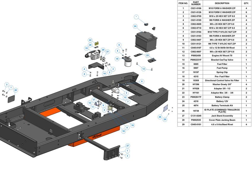
SAFE WORKING 5 / 73
TW 280TVGTR
OPERATOR'S PERSONAL PROTECTIVE EQUIPMENT (PPE)
• Chainsaw safety helmet (EN 397) fitted with mesh visor (EN 1731) and
ear defenders (EN 352).
• Work gloves with elasticated wrist.
• Steel toe cap safety boots (EN 3451).
• Close fitting heavyduty nonsnag clothing. Highvisibility clothing (EN WARNING
471) if risk assessment identifies the need. The chipper will feed material
• Face mask if appropriate. through on its own. To do this, it
• DO NOT wear rings, bracelets, watches, jewellery or any other items that relies on sharp blades both on the
could be caught in the material and draw you into the chipper. feed rollers and the chipper rotor.
To keep the blades sharp, only feed
the machine with clean brushwood.
DO NOT put muddy/dirty wood,
roots, potted plants, bricks, stones
or metal into the chipper.
BASIC WOODCHIPPING SAFETY
The operator should be aware of the following points:
• Maintain a safety exclusion zone around the chipper of at least 10 metres for the general public or employees without
adequate protection. Use hazard tape to identify this working area and keep it clear from debris build up. Chips should
be ejected away from any area the general public have access to.
• Hazardous material Some species of trees and bushes are poisonous. The chipping action can produce vapour, spray
and dust that can irritate the skin. This may lead to respiratory problems or even cause serious poisoning. Check the
material to be chipped before you start. Avoid confined spaces and use a face mask if necessary.
• Be aware when the chipper is processing material that is an awkward shape. The material can move from side to side
in the funnel with great force. If the material extends beyond the funnel, the brash may push you to one side causing
danger. Badly twisted brash should be trimmed before being chipped to avoid thrashing in the feed funnel.
• Be aware that the chipper can eject chips out of the feed funnel with considerable force. Always wear full head and
face protection.
• Always work on the side of the machine furthest from any local danger, e.g. not road side.
• Never leave the chipper unattended when running. Machines must be supervised at all times when in use.
• In the event of an accident, stop the machine, remove the key and call the emergency services immediately.
GENERAL SAFETY MATTERS
• Always stop the chipper engine before making any adjustments, refuelling or cleaning.
• Always check the rotor has stopped rotating and remove the chipper ignition key before maintenance of any kind, or
whenever the machine is to be left unattended. If in doubt, look through the infeed funnel to see if rotor is still moving.
• Always check the machine is well supported and cannot move. If working on an incline, position on solid ground, across
the slope.
ü
• Always operate the chipper with the engine set to maximum speed when chipping.
• Always check (visually) for fluid leaks. If found, resolve the leak before operating the chipper.
• Always take regular breaks. Wearing personal protective equipment for long periods can be tiring
and hot.
• Always keep hands, feet and clothing out of feed opening, discharge and moving parts.
• Always use a push stick to push in short pieces. Under no circumstances should you reach into
the funnel.
• Always keep the operating area clear of people, animals and children.
• Always keep the operating area clear from debris build up.
• Always keep clear of the chip discharge tube. Foreign objects may be ejected with great force.
• Always ensure protective guarding is in place before commencing work. Failure to do so may
result in personal injury or loss of life.
• Always operate the chipper in a well ventilated area exhaust fumes are dangerous.
• Ensure a fire extinguisher is available on site.
• Ensure a personal first aid kit and hand cleaning materials are available (e.g. waterless skin cleanser).
C1900176 08.07.2021 Rev: 4.0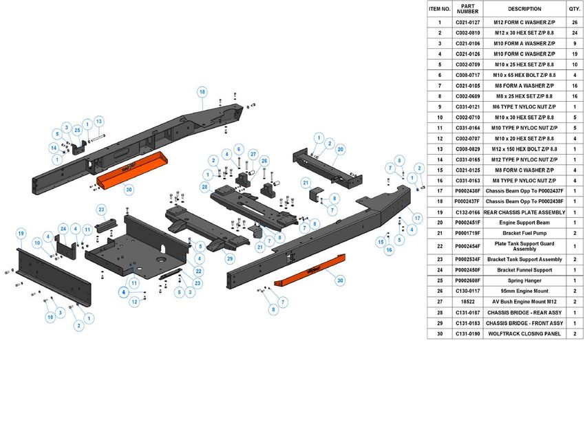
SAFE WORKING 6 / 73
TW 280TVGTR
GENERAL SAFETY MATTERS DO NOT ALLOW
• Do not operate chipper unless available light is THE FOLLOWING
TO ENTER THE
sufficient to see clearly. MACHINE, AS
• Do not use or attempt to start the chipper without the DAMAGE IS
feed funnel, guards and discharge unit securely in place. LIKELY
• Do not stand directly in front of the feed funnel when CLOTH PLASTIC
using the chipper. Stand to one side.
• Do not smoke when refuelling.
• Do not let anyone who has not received
instruction operate the machine.
• Do not climb on the machine at any time.
• Do not handle material that is partially STONES METAL GLASS RUBBER
engaged in the machine.
• Do not touch any exposed wiring while the machine is
running.
• Do not use the chipper inside buildings.
• Do not use the feed funnel to transport any items.
BRICKS STRING ROOTS BEDDING
PLANTS
NOISE TEST
Machine: TW 280TDHB
Notes: Tested chipping 200mm x 200mm corsican pine 1.5m in length
Noise levels above 80dB (A) will be
experienced at the working position.
Prolonged exposure to loud noise may cause
permanent hearing loss. All persons within a
4 metre radius must also wear good quality 87
.9d
ear protection (EN 352) at all times to B(
prevent possible damage to hearing.
A)
Ca
lcu
100.73 dB
99.10 dB late
d
87.9dB(A) Calculated
Guaranteed Sound 95.27 dB 95.23 dB
Power: 118dB (A)
91.90 dB
91.07 dB
R= 4 metres
92.60 dB 92.20 dB
93.33 dB
ed
lat
lcu
a
As required by Annex III of Directive A)C
(
2000/14/EC “Noise Emission in the 87. 9dB
environment by equipment for use outdoors”.
Tested according to BS EN ISO 3744:2010.
R= 10 metres
C1900176 08.07.2021 Rev: 4.0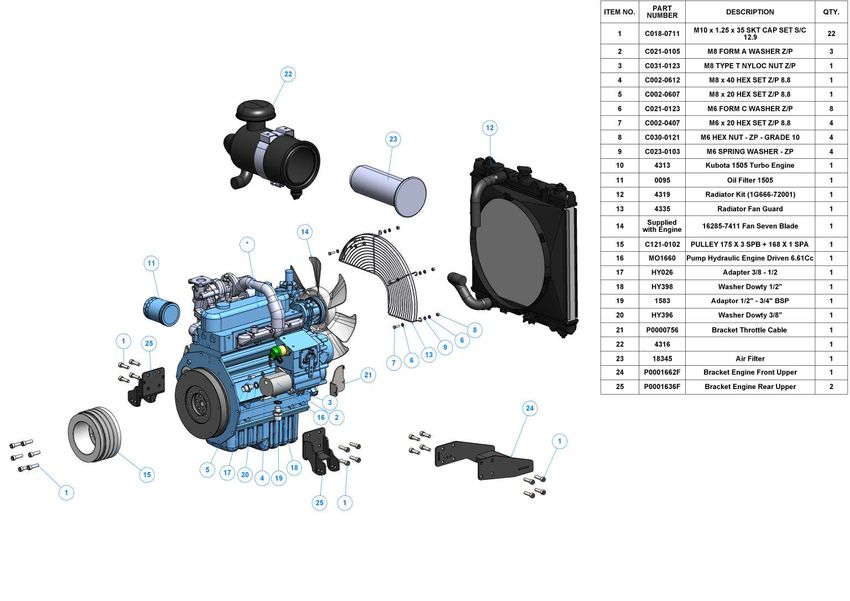
STORAGE 7 / 73
TW 280TVGTR
STORING THE CHIPPER
Perform the following tasks at the storage intervals indicated, following procedures described within this manual.
Storage time
12
Maintenance Tasks month months months months
Allow the engine to cool down. ü ü ü ü
Clean the chipper, removing all woodchips. ü ü ü ü
Perform routine maintenance. ü ü ü ü
Check all fasteners and retighten. ü ü ü ü
Remove all fuel from the tank. NOTE: Either allow the machine to run until all fuel has been
used, or drain from the plug provided. If necessary, siphon the fuel into an approved storage ü ü ü ü
container (refer to refuelling section). Drain prior to moving machinery, to prevent spillage.
Disassemble the spark plug (petrol machines) or remove battery cables (diesel machines). ü ü ü ü
Where paint is damaged, touch up paint or treat with a lubricant. NOTE: Original paint colours
are available from Timberwolf dealers. ü ü ü ü
Store the chipper in a dry place at +5°C to +40°C. NOTE: Timberwolf strongly recommends the
machine is stored in a sheltered location, protected from rain. If the machine is stored outside, x ü ü ü
it must be well protected with tarpaulin.
If relative humidity of the storage environment is > 60%, the shaft of the engine must be
rotated by hand 12 revolutions biweekly. Prior to rotating the shaft, 20 to 30 ml of engine oil x ü ü ü
should be poured onto the bearing liner.
Every 3 months, inspect the machine as per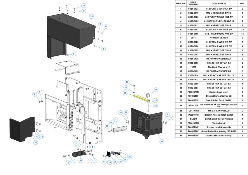
OPERATING INSTRUCTIONS 8 / 73
TW 280TVGTR
RECOMMISSIONING AFTER STORAGE • Inspect cutting blades to confirm they are sharp and
suitable for use.
• Ensure machine is stable.
• Reconnect the battery to its positive and negative
• Remove all guards and check all fasteners. If necessary, terminals.
retighten as described within this manual.
• Undertake electrical diagnostic continuity check, to
• Ensure discharge tube is correctly fastened, free of confirm circuit is complete.
objects or blockages and rotates around its pivot
without being directed to face the point of operation • Relubricate all grease pipes. Remove pipes and bleed
(danger zone). the system prior to use, if necessary. *
• Ensure feed funnel is free from foreign objects e.g. tools • Follow daily checks before starting, as described within
and clothing. this manual.
• Lower and raise feed funnel into its open and closed • Start the machine.
positions to confirm functionality. • Run for 15 minutes at half throttle, prior to any cutting
• Check fuel and hydraulic fluid levels within engine and activity, to clear the combustion engine. Once
reservoir and top up accordingly. * complete, bring the machine onto full throttle for a
further 5 minutes.
• Inspect all internal parts e.g. drive belts, taper locks and
shaft keyways. *Storage fluids should be replaced, DO NOT USE old
stagnate fluids.
• Check belt tension as described within this manual.
VIBRATION DATA
This data is provided to enable assessment of vibration exposure, when the machine is operated in the modes described.
Please refer to local Health & Safety Regulations to determine the daily exposure action and limit values.
TW 280TVGTR, Tracked Hydraulic Fed Chipper, 45hp 1498cc Diesel Engine
Declared vibration emission value in accordance with BS EN 12096:1997
Whole Body Vibrations (m/s2) Hand Arm Vibrations (m/s2)
Measured vibration
1.55 4.55
emission value a
Uncertainty K* 0.62 2.28
Values determined when standing on driver’s platform tracking over soft grassy ground.
Measured vibration
1.80 5.05
emission value a
Uncertainty K* 0.72 2.02
Values determined when standing on driver’s platform tracking over hard paved ground.
*K value calculated according to provisions in BS EN 12096:1997
C1900176 08.07.2021 Rev: 4.0OPERATING INSTRUCTIONS 9 / 73
TW 280TVGTR
DELIVERY
All Timberwolf TW 280TVGTR machines have a full pre delivery inspection before leaving the factory and are ready to
use. Read and understand this instruction manual before attempting to operate the chipper. In particular, read pages 5
6 which contain important health and safety information and advice.
MANUAL CONTROLS
Roller control boxes: a control box is located on either side of the feed funnel. Their function is to control the feed roller
whilst processing material. They do not control the main rotor.
RED SAFETY BAR: This is the large red bar that surrounds the feed tray and side of the feed funnel. The bar is spring
loaded and connected to a switch that will interrupt the power to the rollers. The switch is designed so that it only activates
if the bar is pushed to the limit of its travel. The rollers stop instantly, but can be made to turn again by pressing either the
green feed or blue reverse controls.
Red Safety Bar Test
To ensure the safety bar is always operational it must be activated WARNING
once before each work session. DO NOT REMOVE, JAM,
GREEN FEED CONTROL: forward feed push the feed control once DISABLE, BYPASS,
this activates the rollers and will allow you to start chipping (if the OVERRIDE OR OTHERWISE
rotor speed is high enough). IMPEDE THE
BLUE FEED CONTROL: reverse feed allows you to back material out EFFECTIVENESS OF THE
of the rollers. The rollers will only turn in reverse as long as you keep RED SAFETY BAR.
pressing the feed control.
Control Box Diagram BLUE GREEN
There are two control boxes, located on either side of the REVERSE FORWARD
feed tray. FEED FEED
CONTROL CONTROL
EMERGENCY
STOP (ESD)
RED SAFETY BAR
Do not rely on the red bar to keep the roller
stationary if it is necessary to clear or touch the roller.
Always switch off the machine and remove ignition
key before approaching the roller.
Note: Emergency Stops shown are only included on the
Timberwolf Safety Plus Kit model.
AUTO CONTROLS
The no stress unit controls the feed rate of the material going into the chipping chamber. If the engine speed is below the
predetermined level, the no stress unit will not allow the feed rollers to work in the forward “infeed” direction, until the
rotor speed rises above the predetermined level. At this point, the feed rollers will start turning without warning. The
reverse function will work at any engine speed.
EMERGENCY STOPPING
There are two ways of stopping the TW 280TVGTR chipper in the event of an emergency.
Stopping the Rollers
Activating the red safety bar will stop the rollers immediately. The rotor will still be turning, the engine must be powered
down to stop the rotor. Turn off the engine ignition key. To restart the rollers, just push the green forward or blue reverse
feed control.
Stopping the Engine
Should the engine need to be stopped in an emergency, the engine stop switch located on top of the engine bay should
be pushed. This will shut down the engine in the shortest possible time. The engine cannot be restarted until the engine
stop switch is pulled out and the main ignition switch is turned off to reset the machine.
Stopping the rollers and the engine: Should the entire machine need to be stopped in an emergency, activate
one of the red emergency stop buttons positioned on top of the funnel or on either sides of the feed tray.
This function kills all power to both the engine and the rollers, bringing the machine to a complete stop.
The engine cannot be restarted until the button is restored to its original position and the main ignition
switch is turned off to reset the machine. Before disengaging the emergency stop button, inspect the
machinery to determine the reason for activation.
C1900176 08.07.2021 Rev: 4.0OPERATING INSTRUCTIONS 10 / 73
TW 280TVGTR
ENGINE CONTROLS
The engine controls are in two locations. The engine ignition is on the control panel in the
centre of the machine, and the throttle lever is on the bonnet next to the engine stop switch
(see parts locator on page 3).
CRAWLER TRACK CONTROLS
The TW 280TVGTR is designed to operate in either chip or track mode, but not both at the
same time. The modes can be selected using the toggle switch located on the driving control
panel. The lift function to adjust the gradient and height of machine is available in both
modes.
Chipping Mode
Power is supplied for the chipping function. The feed rollers can be operated as detailed on page 9. The machine cannot
be tracked in this mode but the lift function is available to adjust the height and incline of machine. During any adjustment
power will be diverted from the feed rollers.
Crawler Track Mode
Power is supplied for the tracking function only the machine can be tracked in this mode. The rotor and blades will
remain spinning, but the feed roller controls are inoperable, the lift function is available to adjust the TW 280TVGTR to
suit the terrain.
When Track Mode is selected the two track control valves may be operated. These have direct control over the track
relevant to the each side of the machine. They are proportional valves so increased movement will result in increased
track speed.
Tracking may be done at either high or low engine speed. Manoeuvring the machine in tight spaces, on variable terrain
and while loading/unloading should be done with the engine on low speed.
Lifting Mode
Power is available for the lift function in both chip and track mode. The machine can be lifted by means of the two
control levers, each lever (left and right) controls the lift action of the corresponding track. From its closed position,
when the levers are moved forward, the track will move out horizontally before it lifts the machine take care to allow
for the extra width and height when performing this function. To lower the machine, move the lever in the reverse
direction, the machine will be lowered first before the track is pulled horizontally back into the closed position.
NOTE: ENSURE TRAY IS ROTATED INTO THE UP/CLOSED POSITION PRIOR TO TRACKING TO AVOID
DAMAGE.
The inclinometer (positioned on the top of the feed
funnel) indicates the angle of incline of the chipper,
on the horizontal plane. The chipper can operate
continuously at a 20° incline and up to 10 minutes
at 30° incline.
WARNINGS • ALWAYS WEAR FULL PERSONAL PROTECTIVE EQUIPMENT WHEN DRIVING CHIPPER
(SEE PAGE 5) AND ENSURE BUCKET IS CLOSED WITH DISCHARGE POINTING AWAY
FROM DRIVING POSITION.
• NEVER LEAVE THE CHIPPER ON A SLOPE UNATTENDED. WHEN TRACKING, MA-
CHINES ARE FOR SINGLE OPERATOR USE ONLY. NEVER TRANSPORT PASSENGERS
ON THE DRIVER'S PLATFORM.
• ENSURE THE TRACKS ARE CLEAR OF OBSTRUCTIONS WHEN USING THE VARIABLE
GRADE WOLFTRACKTM CHASSIS.
• DO NOT TRACK THE CHIPPER AT FULL HEIGHT WHEN WORKING ON A GRADIENT.
• NEVER POSITION ANY PART OF YOUR BODY UNDER THE MACHINE AS SERIOUS INJURY
MAY OCCUR.
C1900176 08.07.2021 Rev: 4.0OPERATING INSTRUCTIONS 11 / 73
TW 280TVGTR
DAILY CHECKS BEFORE STARTING
• Locate the machine on firm level ground. • Check the feed tray is in up position to prevent people
• Check the machine is well supported and cannot move. reaching rollers.
• Check all guards are fitted and secure. • Check the controls as described on page 11.
• Check the discharge unit is in place and fastened • Check (visually) for fluid leaks.
securely. • Check fuel and hydraulic oil levels.
• Check the discharge tube is pointing in a safe direction.
For parts location see diagrams on pages 3 & 4.
• Check the feed funnel to ensure no objects are inside.
BEFORE USING THE CHIPPER
It is essential to carry out the following tests to check safety equipment this sequence of tests will only take a few seconds
to carry out. We recommend that these tests are carried out daily. Observing the function as described will confirm that
the safety circuits are working correctly. This is also a good opportunity to remind all operators of the control and
emergency stop systems.
WITH THE ENGINE RUNNING AT FULL SPEED
2 3
1
PRESS THE GREEN FEED CONTROL PRESS THE RED SAFETY PRESS THE BLUE FEED CONTROL
THE IN-FEED SHOULD TURN BAR THE IN-FEED SHOULD TURN BACKWARDS ONLY
FORWARDS THE IN-FEED SHOULD STOP WHILE THE FEED CONTROL IS PRESSED
STARTING THE ENGINE
HOURS
• Ensure throttle lever is in the slow (tortoise) OFF ON HEAT START 12V SOCKET COUNTER
position.
• Insert key. Turn to heat.
• Heater LED comes on.
• Wait for heater LED to go out.
• Turn key to engage starter motor. 1
0 1
• Release key once engine starts. 0
Do not engage starter motor for more than 20 seconds 2 2
allow one minute before attempting to start. 0 0 0 0 0 0 0
Investigate reasons for failure to start. Refer to HOURS
Troubleshooting.
When the engine stop button (or ESD) is pressed it
must be pulled out again and the ignition switch
turned off to reset the machine before attempting to
restart.
CONTROLLING ENGINE SPEED Increase
engine
The engine has variable throttle settings, idle to fast. These are controlled by the speed
throttle lever on the bonnet. Moving the lever towards the ‘Hare’ on the pictogram
will increase engine speed while moving it towards the ‘Tortoise’ will decrease the
engine speed.
STOPPING THE ENGINE
Decrease
• Move the throttle lever to the ‘Tortoise’ to reduce the engine speed to idle. engine
• Leave the engine running for 1 minute. speed
• Turn the power switch to position 0. The engine should stop after a few seconds.
• Remove the ignition key.
For more detailed information refer to the Engine Owner’s Manual.
C1900176 08.07.2021 Rev: 4.0OPERATING INSTRUCTIONS 12 / 73
TW 280TVGTR
DISCHARGE CONTROLS BUCKET ANGLE
Controlling the discharge is an essential part of safe working. Adjust the bucket to the desired angle using the
handle provided.
ROTATION
1 Slacken nut using integral
handle. 1
2 Rotate tube.
3 Retighten nut.
STARTING TO CHIP
• Check that the machine is level and running smoothly.
• Release the catches on the feed tray and lower into the working WARNING
position. Pull to release the red stop button. DO NOT USE OR
• Perform the “before using the chipper” checks (see page 11). This ATTEMPT TO START THE
will take you through the starting procedure and get the machine CHIPPER WITHOUT THE
up to the point of use. PROTECTIVE GUARDING
• Press the green forward feed control. The rollers will begin to turn AND DISCHARGE UNIT
in the forward feed direction. SECURELY IN PLACE.
• Immediately check the function of the red safety bar and also the FAILURE TO DO SO MAY
blue reverse feed controls on both sides of the feed tray. RESULT IN PERSONAL
• Stand to one side of the feed tray. INJURY OR LOSS OF LIFE.
• Repress the green forward feed control.
• Commence feeding material.
CHIPPING
Chipping must be performed at maximum engine speed. Wood up to the recommended diameter can be fed into the
feed funnel. Put the butt end in first and engage it with the feed rollers. The hydraulic feed rollers will pull the branch into
the machine quite quickly. Large diameter material will have its feed rate automatically controlled by the no stress unit.
Sometimes a piece of wood that is a particularly awkward shape is too strong for the feed rollers to break. This will cause
the top roller to either bounce up and down on the wood, or both rollers to stall. If this occurs, press the blue reverse
feed control until the material has been released. Pull the material out of the feed funnel and trim it so the chipper can
handle it.
Both feed rollers should always turn at the same speed. If one or both rollers stop or suddenly slow down it may be that
a piece of wood has become stuck behind one of the rollers. If this occurs, press the blue reverse feed control and hold
for 2 seconds then repress green forward feed control. This should enable the rollers to free the offending piece of
material and continue rotating at the correct speed. If the rollers continue to stall in the 'forward feed' or 'reverse feed',
turn the engine off, remove the ignition key and investigate.
BLOCKAGES
Always be aware that what you are putting into the chipper must
come out. If the chips stop coming out of the discharge tube but the WARNING
chipper is taking material in STOP IMMEDIATELY. Continuing to feed
material into a blocked machine may cause damage and will make it DO NOT REACH INTO THE
difficult to clear. ROTOR HOUSING WITH
UNPROTECTED HANDS.
If the chipper becomes blocked, proceed as follows: THERE ARE SHARP
• Stop the engine and remove the ignition keys. BLADES AND ANY SMALL
• Remove the discharge tube. Check that it is clear. MOVEMENT OF THE
• Wearing gloves, reach into the rotor housing and scoop out the ROTOR MAY CAUSE
majority of the debris causing the blockage. SERIOUS INJURY.
• Replace the discharge tube.
• Restart the engine and increase to full speed.
In the event of heavy blockages the rotor housing access hatch can be removed (see parts locator on page 3).
Allow machine time to clear excess chips still remaining in rotor housing before you continue feeding brushwood. Feed in
a small piece of wood while watching to make sure that it comes out of the discharge. If this does not clear it, repeat the
process and carefully inspect the discharge tube to find any obstruction.
NOTE
Continuing to feed the chipper with brushwood once it has become blocked will cause the chipper to compact the chips
in the rotor housing and it will be difficult and time consuming to clear.
AVOID THIS SITUATION WATCH THE DISCHARGE TUBE AT ALL TIMES.
C1900176 08.07.2021 Rev: 4.0OPERATING INSTRUCTIONS 13 / 73
TW 280TVGTR
BLADE WEAR
The most important part of using a wood chipper is keeping the cutter blades sharp. Timberwolf chipper blades are hollow
ground to an angle of 40 degrees. When performing daily blade checks ensure blade edge is sharp and free from chips, if
there is any evidence of damage, or the edge is “dull” change the blade(s). The TW 280TVGTR is fitted with 2 blades
158mm (6") long. They are 100mm wide when new. A new blade should chip for up to 25 hours before it requires
sharpening. This figure will be drastically reduced by feeding the machine with stony, sandy or muddy material.
As the blade becomes blunt, performance is reduced. With increased stress and load on the machine the chips will become
more irregular and stringy. At this point the blade should be sent to a reputable blade sharpening company. The blade
can be sharpened several times in its life. A wear mark indicates the safe limit of blade wear. Replace when this line is
exceeded.
The machine is also fitted with a static blade (anvil). It is important that the anvil is in good condition to allow the cutting
blades to function efficiently. Performance will be poor even with sharp cutter blades if the anvil is worn.
HYDRAULIC OIL LEVEL AND TEMPERATURE INDICATOR
The indicator is situated on the side of the hydraulic oil tank. The hydraulic oil level should be within the upper and lower
level marks. Refer to filling and draining instructions on page 22.
When the chipper is running, the oil temperature should not
exceed 65oC. If it does, stop the machine immediately. Failure
to do so may result in damage. Overheating can result from the
chipper being worked extremely hard in hot conditions, as the
oil is not getting a chance to cool down. Stop the chipper and
allow oil to cool before continuing. If the temperature goes
above 65oC and the machine is not being worked hard or the air
temperature is not particularly high, this indicates low oil, a jammed
hydraulic motor or valve. Stop immediately and investigate.
When the chipper is on level ground, the oil level should sit
between the red line at the bottom of the gauge and the blue
line at the top. If this level drops significantly it indicates an oil
leak. Stop immediately and investigate.
FUEL LEVEL INDICATOR
The fuel level can be seen through the wall of the plastic tank.
REFUELLING
When refuelling, follow standard Health & Safety practices:
• Stop the engine and allow to cool before refuelling.
• Never smoke or allow naked flames nearby while refuelling.
• Store fuel away from vapour ignition sources such as fires and people smoking.
• Never refuel at operating location, keep a distance of > 10 m to avoid creating fire hazards.
• Fuel storage containers must be approved for appropriate fuel storage and clearly labelled with securely fitting caps.
• Clean area around fuel cap and use a funnel for refuelling. Replace the fuel cap securely. Do not fill the tank beyond
the max. fill indicator.
• Avoid skin contact with fuel. If it gets into eyes wash out with sterile water immediately and seek medical advice as
soon as possible.
• Always clean spillages quickly and change clothes before reentering the work area if fuel is spilled onto garments.
WINCH OPERATION
Where a winch is factory fitted, it is for recovery purposes only. Always follow the winch manufacturer’s instruction manual
provided with the machine. Never winch while an operator is on the driver’s platform.
C1900176 08.07.2021 Rev: 4.0OPERATING INSTRUCTIONS 14 / 73
TW 280TVGTR
TROUBLESHOOTING
This table is a troubleshooting guide to common problems.
If your problem is not listed below, or is unresolved after following the guide, please contact your Timberwolf service
agent, whose Timberwolf trained engineers can perform further fault finding. Before you call, please have this operating
manual and the machine serial number ready.
Problem Cause Solution Caution Always ensure appropriate PPE is worn.
Obstructed Ensure machine is off and keys
Clear debris from discharge chute.
Wood chip discharge removed.
ejection Ensure machine is off and keys
Loose drive belts Refer to manual & tension belts guidelines.
stopped / removed.
limited Broken rotor Inspect paddles, replace broken / missing Ensure machine is off and keys
paddles paddle. removed. Call engineer for repair.
Obstructed Ensure machine is off and keys
Clear debris from discharge chute.
discharge removed.
Rotor does Inspect & clear infeed funnel, roller box and Ensure machine is off and keys
Rotor jammed
not turn rotor housing. removed.
Inspect drive belts, replace if required. Ensure machine is off and keys
Drive belt issue
Refer to manual & tension belts guidelines. removed.
Check & inspect throttle and cable. Check Ensure machine is off and keys
Low engine speed
throttle is set to specified speed. removed.
Infeed rollers Inspect & clear infeed funnel, roller box and Ensure machine is off and keys
jammed rotor housing. removed.
Check hydraulic oil level, top up if Ensure machine is off, cool & pressure
Hydraulic oil
Slow or not necessary. isn’t present within the system.
feeding Ensure machine is off and keys
Blades dull Rotate, sharpen or replace blades.
removed.
Check anvil has sharp edge, rotate, sharpen Ensure machine is off and keys
Anvils dull
or replace if necessary. removed.
Obstructed Ensure machine is off and keys
Clear debris from discharge chute.
discharge removed.
THE FOLLOWING PAGES DETAIL ONLY BASIC
MAINTENANCE GUIDELINES SPECIFIC TO YOUR CHIPPER.
THIS IS NOT A WORKSHOP MANUAL.
The following guidelines are not exhaustive and do not extend to generally accepted standards of
engineering/mechanical maintenance that should be applied to any piece of mechanical equipment and the chassis
to which it is mounted.
Authorised Timberwolf service agents are fully trained in all aspects of total service and maintenance of Timberwolf
wood chippers. You are strongly advised to take your chipper to an authorised agent for all but the most routine
maintenance and checks.
Timberwolf accepts no responsibility for the failure of the owner/user of Timberwolf chippers to recognise generally
accepted standards of engineering/mechanical maintenance and apply them throughout the machine.
The failure to apply generally accepted standards of maintenance, or the performance of inappropriate maintenance
or modifications, may invalidate warranty and/or regulatory compliance, in whole or in part.
Please refer to your authorised Timberwolf service agent for service and maintenance.
C1900176 08.07.2021 Rev: 4.0SERVICE INSTRUCTIONS 15 / 73
TW 280TVGTR
SERVICE SCHEDULE
WARNING
ALWAYS IMMOBILISE THE MACHINE BY STOPPING THE ENGINE, REMOVING THE
IGNITION KEY AND DISCONNECTING THE BATTERY BEFORE UNDERTAKING ANY
MAINTENANCE WORK.
Daily 50 100 500 1
SERVICE SCHEDULE
Check Hours Hours Hours Year
Check coolant level. ü
Check radiator is clear. ü
Check engine oil top up if necessary (10W30). ü
Check for engine oil / hydraulic oil leaks. ü
Check fuel level. ü
Check hydraulic oil level. ü
Check feed funnel, feed roller cover, access covers,
engine covers and discharge unit are securely fitted. ü
Check blades. ü
Check air intake is clear. ü
Clean air filter element. DEPENDING ON WORKING ENVIRONMENT
Check safety bar mechanism. ü
Check for tightness all nuts, bolts and fastenings
making sure nothing has worked loose. ü
Grease discharge flange. ü
Check tension of main drive belts (and tension if
necessary). ü
Grease the roller box slides. ü OR AS REQUIRED SEE PAGE 21
Grease the roller spline and bearing. ü OR AS REQUIRED SEE PAGE 21
Check anvils for wear. ü
Check fuel pipes and clamp bands. ü
Check for loose electrical wiring. ü
FIRST TIME THEN OR
Replace track drive unit oil
ü ü ü
Replace hydraulic oil filter every year or 100 hours
after service or repair work to the hydraulic system. ü OR ü
Replace hydraulic oil. ü OR ü
Grease tandem pump spline drive ü
Replace fuel pipes and clamp bands.
Check coolant condition.
Change engine oil. REFER TO YOUR ENGINE SUPPLIER’S MANUAL
Replace engine oil filter cartridge.
Check valve clearance.
Replace anvils when worn. RETURN TO DEALER FOR ANVIL CHANGE
C1900176 08.07.2021 Rev: 4.0SERVICE INSTRUCTIONS 16 / 73
TW 280TVGTR
SAFE MAINTENANCE
• Handle blades with extreme caution to avoid injury. Gloves
should always be worn when handling the cutter blades.
• The drive belts should be connected while changing blades, as
this will restrict sudden movement of the rotor.
• The major components of this machine are heavy. Lifting
equipment must be used for disassembly. WARNING
• Clean machines are safer and easier to service. ALWAYS IMMOBILISE THE ENGINE BEFORE
UNDERTAKING ANY MAINTENANCE WORK
• Avoid contact with hazardous materials. ON THE CHIPPER BY REMOVING THE KEY
AND DISCONNECTING THE BATTERY.
ENSURE THE CHIPPER IS STABLE BEFORE
SAFE LIFTING & SECURING DOWN OF THE PERFORMING ANY MAINTENANCE.
CHIPPER
The lifting eye is designed to lift the machine’s weight only. Do not use hoist hook directly
on the lifting eye, use a correctly rated safety shackle. Inspect the lifting eye prior to each
use DO NOT USE LIFTING EYE IF DAMAGED. Maximum lift weight is 2500kg, as indicated
on the machine.
The method of securing the chipper can vary depending on the type of carrier and position
of tie down points available on the carrier. Timberwolf recommend where possible to
secure machine to carrier using correctly rated ratchet straps as shown.
Securing a Timberwolf chipper ready for transport must be carried out by competent
qualified personnel. Failure to observe this procedure could result in chassis and/or
undercarriage damage.
SPARES
Only fit genuine Timberwolf replacement blades, screws and
chipper spares. Failure to do so will result in the invalidation of
the warranty and may result in damage to the chipper, personal
injury or even loss of life.
5000kgs x 50mm wide
(minimum) ratchet strap
BATTERY REMOVAL AND MAINTENANCE
Battery Removal
1 The battery is located within the control tower.
2 Remove the seven M6 bolts securing the driving controls front guard.
3 Remove the two M10 bolts securing the battery clamp.
4 Remove the negative battery lead.
5 Remove the positive battery lead.
WARNING
Battery Maintenance REFER TO THE BATTERY SAFETY
1 Remove the seven M6 bolts securing the driving controls front guard. SECTION ON PAGES 18.
2 The battery can be serviced in this position.
CHECK FITTINGS
The Timberwolf TW 280TVGTR is subject to large vibrations during the normal course of operation. Consequently there is
always a possibility that nuts and bolts will work themselves loose. It is important that periodic checks are made to ensure
the security of all fasteners. Fasteners should be tightened using a torque wrench to the required torque (see below).
Uncalibrated torque wrenches can be inaccurate by as much as 25%. It is therefore essential that a calibrated torque
wrench is used to achieve the tightening torques listed below.
Size Pitch Head Torque Ib ft Torque Nm
Blade Bolts M16 Standard 24mm Hex 125 170
Anvil Bolts M12 Standard M12 Cap 65 88
General M8 Standard 13 mm Hex 20 27
General M10 Standard 17 mm Hex 45 61
General M12 Standard 19 mm Hex 65 88
Drain Bung in Fuel Tank 3/8” BSP 22 mm Hex 15 20
C1900176 08.07.2021 Rev: 4.0SERVICE INSTRUCTIONS 17 / 73
TW 280TVGTR
HAZARDOUS MATERIALS & END OF MACHINE LIFE
During Machine Life
The following hazardous materials are supplied within Timberwolf machines:
• Engine oil
• Coolant
• Battery acid
• Hydraulic oil
• Diesel/Petrol
• Copper Ease
MATERIAL SAFETY DATA SHEETS FOR HAZARDOUS MATERIALS SUPPLIED WITHIN TIMBERWOLF
MACHINES ARE AVAILABLE ON REQUEST. REFER TO THESE FOR FIRST AID AND FIRE PROTECTION
MEASURES.
Always follow recommended procedures for safe handling, removal and disposal of hazardous materials. Safety precautions
should be taken when handling hazardous materials (use of oilresistant gloves and safety glasses are recommended
respiratory protection is not required). Avoid direct contact with the substance and store in a cool, well ventilated area
avoiding sources of ignition, strong oxidising agents and strong acids. Ensure hazardous spillages do not flow into the
ground or drainage system and ensure potential environmental damage is controlled safely, according to local laws.
End of Machine Life
Follow these guidelines using approved local waste and disposal agencies for recycled materials, according to applicable
Health, Safety and Environmental laws.
• Position the machine within reach of all necessary lifting equipment.
• Use tools and PPE detailed within maintenance instructions.
• Remove all hazardous materials and battery and store safely before disposal.
• Disassemble the machine structure, referring to the maintenance instructions. Pay attention to parts with mechanical
pressure or tension applied, including springs.
• Separate items that continue to have a service life.
• Separate worn items into material groups and where possible, recycle using available agencies for recycled materials.
Common types are:
Steel Plastic materials
Nonferrous metals Rubber
Aluminium Electrical and Electronic Components
Brass Other materials that can be recycled
Copper Other materials that cannot be recycled
• If a part is not easily separated into different material groups, it must be added to “general discarded materials”.
• Do not burn discarded materials.
• Change the machinery records to show that the machine is out of service and discarded. Supply this serial number to
Timberwolf to close their records.
C1900176 08.07.2021 Rev: 4.0SERVICE INSTRUCTIONS 18 / 73
TW 280TVGTR
BATTERY SAFETY INFORMATION
WARNING NOTES AND SAFETY REGULATIONS FOR FILLED LEAD-ACID BATTERIES
• For safety reasons, wear eye Corrosive hazard: suds, and rinse with plenty of
protection when handling a Battery acid is highly corrosive, water.
battery. therefore: • If acid is swallowed, consult a
• Keep out of reach of • Wear protective gloves and doctor immediately.
children. eye protection. Warning notes: The battery case
• Fires, sparks, naked flames • Do not tilt the battery, acid can become brittle, to avoid this:
and smoking are prohibited. may escape from the vent • Do not store batteries in
• Avoid causing sparks when openings. direct sunlight.
dealing with cables and First aid: • Discharged batteries may
electrical equipment, and • Rinse off acid splashed in the freeze up, therefore store in
beware of electrostatic eyes immediately for several an area free from frost.
discharges. minutes with clear water! Disposal:
• Avoid short circuits. Remove contact lenses if • Dispose of old batteries at an
Explosion hazard: worn and continue rinsing. authorised collection point.
• A highly explosive Then consult a doctor • The notes listed under item 1
oxyhydrogen gas mixture is immediately. are to be followed for
produced when batteries are • Neutralise acid splashes on transport.
charged. the skin or clothes • Never dispose of old batteries
immediately with acid in household waste.
neutraliser (soda) or soap
1. Storage and transport positive output of the charger. Connect the negative
• Batteries are filled with acid. terminal accordingly.
• Always store and transport batteries upright and prevent • Switch on the charger only after the battery has been
from tilting so that no acid can escape. connected, and switch off the charger first after charging
• Store in a cool and dry place. has been completed.
• Do not remove the protective cap from the positive • Charging currentrecommendation: 1/10 ampere of the
terminal. battery capacity Ah.
• Run a FIFO (first infirst out) warehouse management • Use a charger with a constant charging voltage of 14.4V
system. for recharging.
2. Initial operation • If the acid temperature rises above 55o Celsius, stop
charging.
• The batteries are filled with acid at a density of 1.28g/ml
during the manufacturing process and are ready for use. • The battery is fully charged when the charging voltage
has stopped rising for two hours.
• Recharge in case of insufficient starting power (see no. 4).
5. Maintenance
3. Installation in the vehicle and removal from the vehicle
• Keep the battery clean and dry.
• Switch off the engine and all electrical equipment.
• Use a moist antistatic cloth only to wipe the battery,
• When removing, disconnect the negative terminal first. otherwise there is a danger of explosion.
• Avoid short circuits caused by tools, for example. • Do not open the battery.
• Remove any foreign body from the battery tray, and • Recharge in case of insufficient starting power (see no. 4).
clamp battery tightly after installation.
6. Jump Starting
• Clean the terminals and clamps, and lubricate slightly
with battery grease. • Use the standardised jumper cable in compliance with
DIN 72553 only, and follow the operating instructions.
• When installing, first connect the positive terminal, and
check the terminal clamps for tight fit. • Use batteries of the same
nominal voltage only. (2) (1)
• After having fitted the battery in the vehicle, remove the
protective cap from the positive terminal, and place it on • Switch off the engines of
the terminal of the replaced battery in order to prevent both vehicles. 12V 12V
short circuits and possible sparks. • First connect the two positive
• Use parts from the replaced battery, such as the terminal terminals (1) and (2), then (3) (4)
covers, elbows, vent pipe connection and terminal connect the negative
holders (where applicable); use available or supplied filler terminal of the charged battery (3) to a metal part (4) of
caps. the vehicle requiring assistance away from the battery.
• Leave at least one vent open, otherwise there is a danger • Start the engine of the vehicle providing assistance, then
of explosion. This also applies when old batteries are start the engine of the vehicle requiring assistance for a
returned. maximum of 15 seconds.
4. Charging • Disconnect the cables in reverse sequence (4321).
• Remove the battery from the vehicle; disconnect the lead 7. Taking the battery out of service
of the negative terminal first. • Charge the battery; store in a cool place or in the vehicle
• Ensure good ventilation. with the negative terminal disconnected.
• Use suitable direct current chargers only. • Check the battery state of charge at regular intervals, and
correct by recharging when necessary (see no. 4).
• Connect the positive terminal of the battery to the
C1900176 08.07.2021 Rev: 4.0SERVICE INSTRUCTIONS 19 / 73
TW 280TVGTR
CHANGE BLADES
WARNING
WEAR RIGGERS GLOVES FOR THE BLADE
CHANGING OPERATION.
1 Turn the chipper off and remove the ignition keys.
2 Remove battery leads.
3 Remove the 3 nuts retaining the access hatch, slide hatch clear of rotor
housing.
3 4 Turn rotor to blade change position.
5 Insert locking bar into rotor housing and rotor.
6 Brush away all dirt and debris from the rotor and blades.
7 With a 24mm spanner/socket undo the 2 nyloc nuts and washers that are
holding the blade in place.
8 Remove blade bolts while holding blade in position. The inner bolt on the
inner blade passes through the hole in the roller box. If necessary tap the
bolts to loosen.
9 Grasp the blade by the flat edges while wearing heavy duty gloves.
10 Withdraw the blade from the rotor.
4 11 Rotate blade to use 2nd edge or replace with a new or sharpened blade.
12 Clean the back surface of the blade, blade bolts and blade area of the rotor
before reseating blades. The blades must not have any material
underneath them when tightened. If they are not flat and tight they will
become loose very quickly.
13 Reassemble the blades, bolts, washers and nuts in the order shown in the
8 diagram above. Use only genuine Timberwolf nuts and washers, as they
are of a higher grade than normally stocked at fastener factories. Failure
to use the appropriate grade nuts or washers may result in damage, injury
5 or death. The use of genuine Timberwolf blades and bolts is recommended.
14 Apply a smear of anti seize compound (copper ease) to the bolt threads and
back face of the nuts. Do not apply copper grease onto the counter bore
faces of the blades or bolts.
15 A calibrated torque wrench must be used to tighten the bolts to a torque
setting of 125 lbs ft (170 Nm).
10
16 Remove lock pin, rotate rotor to next blade then replace lock pin and
repeat steps 6 14.
17 Refit access hatch.
18 Refit the nuts and tighten to 40 lbs ft (54 Nm).
19 Refit battery leads.
WARNING
ALWAYS SHARPEN BLADES ON A REGULAR BASIS. FAILURE TO DO SO
WILL CAUSE THE MACHINE TO UNDER PERFORM AND WILL OVERLOAD
ENGINE AND BEARINGS CAUSING MACHINE BREAKDOWN. BLADES
MUST NOT BE SHARPENED BEYOND THE WEAR MARK (SEE DIAGRAM).
FAILURE TO COMPLY WITH THIS COULD RESULT IN MACHINE DAMAGE,
INJURY OR LOSS OF LIFE. WEAR MARK
C1900176 08.07.2021 Rev: 4.0SERVICE INSTRUCTIONS 20 / 73
TW 280TVGTR
TENSION DRIVE BELTS
NOTE: There will normally be a rapid drop in tension during runin period for new belts. When new belts are fitted,
check the tension every 2 3 hours and adjust until the tension remains constant. Belt failures due to lack of correct
tensioning will not be covered under your Timberwolf warranty.
1 Remove engine bay side panel.
2 Loosen bolt in centre of tensioner pulley with a 19 mm spanner so that
pulley is able to slide with minimal wobble.
3 Turn nut in end of tensioner pulley slider until correct belt tension is 3
achieved. For instructions on checking belt tension & correct belt tension
values, please refer to the Timberwolf VBelt Tensioning Data Table (page
36).
4 Retighten bolt in centre of tensioner pulley.
5 Run machine and test, recheck belt tension.
NOTE: Slack drive belts will cause poor performance and excess belt and pulley
2
wear.
TENSION HYDRAULIC PUMP BELT
1 Loosen the M8 hex nut (1) to the end of the thread.
2 Loosen the two M10 screws (2) one turn. 2
3 Adjust the long M8 screw (2) to achieve the correct belt tension. For
instructions on checking belt tension and correct belt tension values,
please refer to the Timberwolf VBelt Tensioning Data Table (pg. 36).
4 Tighten the two M10 securing screws (2)
5 Check the belt tension again. If the M10 screws (2) are loosened 3
too much a difference of belt tension will occur after the screws are
fastened. 1
6 Tighten the M8 hex nut (1).
GREASE THE DISCHARGE FLANGE 2
1 Remove the discharge tube.
2 Apply multipurpose grease to surface shown.
3 Refit discharge tube.
C1900176 08.07.2021 Rev: 4.0SERVICE INSTRUCTIONS 21 / 73
TW 280TVGTR
GREASE THE ROLLER SPLINE AND ROTOR BEARINGS
NOTE: This should be done regularly. In dirty and dusty conditions or during periods of hard work it should be daily. If
the bearings and splines are allowed to run dry premature wear will occur resulting in a breakdown and the need for
replacement parts. This failure is not warranty. Early signs of insufficient grease includes squeaking or knocking rollers.
1 Locate the greasing panel.
2 Apply 4+ pumps of grease to each nipple. 1
3 It is recommended to grease all the nipples whilst the engine is
running and rollers are turning to distribute the grease evenly. DO
NOT USE GRAPHITE BASED GREASE.
D
4 Both front and rear bearings are greased by nipples A and B. The top A B C
and bottom roller splines are greased by nipples C and D.
GREASE THE ROLLER BOX SLIDES
NOTE: This should be done regularly. In dirty or dusty conditions or 3
during periods of hard work it should be done weekly. If the slides
become dry the top roller will tend to hang up and the pullingin power
of the rollers will be much reduced. Excessive wear will ensue.
1 Turn the chipper off and remove the ignition keys.
2 Ensure machine has come to a complete stop remove battery leads.
4
3 Remove the 6 nuts and washers retaining the roller box guard and
remove guard.
4 Remove the rotor housing blade access hatch as per blade change
procedure.
5 Apply thin grease with a brush directly to the slide surfaces indicated,
including inner cheeks of slider. DO NOT USE GRAPHITE BASED
GREASE.
5
6 Replace rotor housing blade access hatch then top guard. Refit nuts
and washers.
7 Refit battery leads.
ENGINE SERVICING
All engine servicing must be performed in accordance with the Engine Manufacturer’s Handbook provided with the
machine. Failure to adhere to this may invalidate warranty and/or shorten engine life.
CHECK HOSES
All the hydraulic hoses should be regularly inspected for chafing, leaks and overall good condition. Identify the hoses
that run to the top motor and track motors as these have the highest chance of damage as they are constantly moving.
If any hydraulic components are changed, new seals should be installed during reassembly. Fittings should then be
retightened.
C1900176 08.07.2021 Rev: 4.0SERVICE INSTRUCTIONS 22 / 73
TW 280TVGTR
CHANGE HYDRAULIC OIL AND FILTER
1
WARNING
6 USE PLASTIC GLOVES TO KEEP OIL OFF SKIN
AND DISPOSE OF THE USED OIL AND FILTER
IN AN ECOLOGICALLY SOUND WAY. THE OIL
AND FILTER SHOULD BE CHANGED ONCE A
YEAR OR AT ANY TIME IT BECOMES
CONTAMINATED. BEFORE STARTING CHECK
THAT THE CHIPPER IS STANDING LEVEL AND
BRUSH AWAY LOOSE CHIPS.
NOTE: This is a nonadjustable air breather filter.
1 Remove the black screw cap from the filter housing. 6 Refill with VG 32 hydraulic oil until the level is between
2 Partially remove the filter element from the inner cup. the min and the max lines marked on the tank (about
Leave the filter to drain for 15 minutes. 48 litres).
3 Remove the filter element from the cup when it’s clear 7 Refit the filter cup, install a new filter element and refit
of hydraulic oil. the black screw cap to the filter housing ensuring the
oring remains in place.
4 Remove the drain plug and drain the oil into a suitable
container.
5 Replace the drain plug.
TRACK BASE MAINTENANCE
Safe Maintenance • Keep the tracks clean, removing excess oil, grease
• Solidly support the under carriage if it needs to be and dirt.
lifted up for maintenance . • Check for oil leaks and damaged hoses.
• Hydraulic systems may get very hot after working. • Only use recommended lubricants. Do not mix
• Keep all components in good condition as they are different brands.
exposed to high pressures. • Keep track stretcher grease nipples clean.
• Immediately repair damage and replace worn or
broken items.
Maintenance intervals are only guidelines. The amount of times maintenance is conducted should be increased beyond
recommended guidelines if severe conditions are encountered.
REPLACEMENT OF OIL IN THE TRACK DRIVE UNIT OIL FILL
To fill with oil, track the machine until the gearbox casing is level with a plug positioned
at 12 o’clock as shown. Unscrew the two plugs and fill from the upper hole until oil
reaches the level of the lower hole.
NOTE Ensure the correct grade of oil is used: Gear Oil EP80W90 GL5
MAXIMUM LEVEL
DRAINING THE OIL IN THE TRACK DRIVE UNIT
To drain the oil, track the machine until a plug is at 6 o’clock as shown. Unscrew both
plugs and allow oil to discharge into a suitable container. Dispose of waste oil in a safe
and approved way.
VENTING
REDUCTION UNIT OIL TYPES
We recommend, for track drive gearboxes, using gear oils with E>P. additives and viscosity
to SAE 80W/90 or ISO VG 150. Continuous duty temperature must not exceed 90oC.
DRAIN PORT
C1900176 08.07.2021 Rev: 4.0You can also read