Inverter generator BE1200I BE2100I - user manual - BE Power Equipment
←
→
Page content transcription
If your browser does not render page correctly, please read the page content below

inverter generator

      BE1200I
      BE2100I

    user manual
TABLE OF CONTENTS                     TABLE OF CONTENTS

    Safety                                   Maintenance
    4 Introduction                           25 Maintenance
    5 Safety Warnings                        27 Spark plug inspection
    6 Safety Information                     28 Carburetor adjustment
    Description                              28 Engine oil replacement
    10 Description                           29 Air filter
    11 Control Panel                         30 Muffler screen and spark Arrester
                                             31 Fuel tank filter
    Control Function                         31 Fuel filter
    12 3 in 1 switch knob
    12 Oil warning light (red)               Storage
    13 Overload indicator light (red)        32 Drain the fuel
    13 AC pilot light (green)                32 Engine
    14 DC protector
                                             Troubleshooting
    14 Engine smart control (ESC)
                                             32 Engine won’t start
    15 Fuel tank cap
                                             34 Generator won’t produce power
    15 Fuel tank cap air vent knob
    15 Ground (Earth) terminal               34 Specifications
                                             35 Wiring Diagram
    Preparation
    16 Fuel                                  Warranty
    16 Engine oil                            36 Warranty
    17 Pre-operation check
    Operation
    18 Operation
    19 Staring the engine
    20 Stopping the engine
    21 Alternating Current (AC) connection
    21 Battery Charging
    23 Application range

2                                                                                   3
INTRODUCTION                                                                         SAFETY

                      Attention: Read through the complete manual           Save these Instructions
                      prior to the initial use of your generator.           Safety Warnings
                                                                                                 This is the safety alert symbol. It is used to alert
                                                                                                 you to potential personal injury hazards. Obey
                                                                                                 all safety messages that follow this symbol to
Using the Operator’s manual                                                                      avoid possible injury or death.
The operating manual is an important part of your generator and should
be read thoroughly before initial use, and referred to often to make sure
adequate safety and service concerns are being addressed.                   The safety alert symbol ( ) is used with a signal word (DANGER,
                                                                            CAUTION, WARNING), a pictorial and/or a safety message to alert
Reading the owner’s manual thoroughly will help avoid any personal injury   you to hazards.
or damage to your machine. By knowing how best to operate this
machine you will be better positioned to show others who may also            DANGER       Indicates a hazard which, if not avoided, will result in death or
operate the unit.                                                                         serious injury.
This manual contains information for the complete range of BE               WARNING Indicates a hazard which, if not avoided, could result in death or
generators, and was written to take you from the safety requirements                      serious injury.
to the operating functions of your machine. You can refer back to the        CAUTION Indicates a hazard which, if not avoided, might result in minor or
manual at any time to help troubleshoot any specific operating functions,                 moderate injury.
so store it with the machine at all times.
                                                                              NOTICE      Indicates a situation that could result in equipment damage.
                                                                                          Follow safety messages to avoid or reduce the risk of injury or
If you need to contact an Authorized Dealer or Customer Service line for                  death.
information on servicing or warranty claims, always provide the product
model and identification numbers.
You will need to locate the model and serial number for the machine and                          Hazard Symbols and Meanings
record the information in the places provided below.

 Date of Purchase:
 Dealer Name:                                                                       explosion                  fire                  electric shock

 Dealer Phone:

                   Product Identification Numbers
 Model Number:
                                                                                   toxic fumes               kickback                 read manual
 Serial Number:

4                                                                                                                                                             5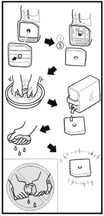
SAFETY                                                                SAFETY

1. SAFETY INFORMATION                                                                                      WARNING
Read and understand this owner’s manual before operating your
generator. It will help you avoid accidents if you are familiar with your                   Fuel and its vapors are extremely flammable and
generator’s safe operation procedures.                                                      explosive.

                                                                                            Fire or explosion can cause severe burns or death.
                                 WARNING
                                                                            When Adding or Draining Fuel
                 Generator exhaust contains carbon monoxide, a              • Observe all safety regulations for the safe handling of fuel. Handle
                 poisonous gas that can kill you.                             fuel in safety containers. If the container does not have a spout, use
                                                                              a funnel.
                 You CANNOT smell or see this gas.                          • Do not overfill the fuel tank, leave room for the fuel to expand.
                                                                            • Do not refill fuel tank while the engine is running. Before refueling the
                                                                              generator, turn it off and let it cool down. Gasoline spilled on hot
 • Use the generator outdoors, away from open windows, vents, or              engine parts could ignite.
   doors that could allow the carbon monoxide gas to come indoors.          • Fill the tank only on an area of bare ground. While fueling the tank,
   Keep the generator at least 1 meter (3 feet) away from any structure       keep heat, sparks and open flame away. Carefully clean up any spilled
   or building during use.                                                    fuel before starting engine.
 • NEVER use a generator indoors, including in homes, garages,              • Always fill fuel tank in an area with plenty of ventilation to avoid
   basements, crawl spaces, and other enclosed or partially-enclosed          inhaling dangerous fumes.
   areas, even with ventilation. Opening doors and windows or using         • NEVER store fuel for your generator in the home. Gasoline, propane,
   fans will not prevent carbon monoxide build-up in the home.                kerosene, and other flammable liquids should be stored outside of
 • NEVER use a generator in enclosed or partially-enclosed spaces.            living areas in properly-labeled, non-glass safety containers. Do not
   Generators can produce high levels of carbon monoxide very quickly.        store them near a fuel-burning appliance, such as a natural gas water
   When you use a portable generator, remember that you cannot smell          heater in a garage. If the fuel is spilled or the container is not sealed
   or see carbon monoxide. Even if you can’t smell exhaust fumes, you         properly, invisible vapors from the fuel can travel along the ground and
   may still be exposed to carbon monoxide.                                   can be ignited by the appliance’s pilot light or by arcing from electric
 • NEVER operate the generator in an explosive atmosphere, near               switches in the appliance.
   combustible materials or where ventilation is not sufficient to carry
   away exhaust fumes. Exhaust fumes can cause serious injury or death.
 • If you start to feel sick, dizzy, or weak while using a generator, get
   to fresh air RIGHT AWAY. DO NOT DELAY. The carbon monoxide
   from generators can rapidly lead to full incapacitation and death.
                                                                                                !
 • If you experience serious symptoms, get medical attention                                This product can expose you to chemicals
                                                                                            including lead, which is known to the State
   immediately. Inform medical staff that carbon monoxide poisoning                         of California to cause cancer and birth
   is suspected. If you experienced symptoms while indoors, have                            defects or other reproductive harm. For more
   someone call the fire department to determine when it is safe to                         information, go to www.P65Warnings.ca.gov.
   re-enter the building.                                                                   Wash hands after handling.

6                                                                                                                                                     7
SAFETY SAFETY
Ground Fault Circuit Interrupter Protection This product has been designed with internal grounding or floating
bonded neutral. If it should malfunction or breakdown, grounding
These generators are equipped with a GFCI (Ground Fault Circuit provides a path of least resistance for electric current to reduce the risk
Interrupters) 120V duplex receptacles for protection against the hazards of electric shock.
of electrical shock from defective attachments such as, tools, cords,
and cables. DANGER
WARNING Improper grounding can result in a risk of electrocution.
Check with a qualified electrician for your local
• The GFCI may not function unless the generator is properly
requirements if you are in doubt as to whether the unit
grounded. Follow the correct procedure specified in the section
is properly grounded.
labeled GROUNDING INSTRUCTIONS.
• This generator is equipped with a grounding terminal for added
A GFCI is a device that interrupts electricity from either the utility or protection. Using the ground path from the generator to an external
generator by means of a special type of circuit breaker that determines if ground source as instructed in the section labeled “Grounding
a current flow to the ground occurs. Instructions” in the Preparation section of this manual can be
A GFCI can be used only with generators that have the neutral wire necessary. Please consult a qualified electrician for local regulations.
internally bonded to the frame, and the frame properly grounded to the • The generator is a potential source of electrical shock if not kept dry.
earth. A GFCI will not work on generators that do not have the neutral Keep the generator dry and do not use in rain or wet conditions. To
wire bonded to the frame, or on generators which have not been properly protect from moisture, operate it on a dry surface under an open,
grounded. canopy-like structure. Dry your hands if wet before touching the
generator.
• Plug appliances directly into the generator. Or, use a heavy duty,
outdoor-rated extension cord that is rated (in watts or amps) at least
equal to the sum of the connected appliance loads. Check that the
entire cord is free of cuts or tears and that the plug has all three
prongs,especially a grounding pin.
• NEVER try to power the house wiring by plugging the generator into
a wall outlet, a practice known as “back feeding”. This is an extremely
dangerous practice that presents an electrocution risk to utility
workers and neighbors served by the same utility transformer. It also
bypasses some of the built-in household circuit protection devices.
• If you must connect the generator to the house wiring to power
appliances, have a qualified electrician install the appropriate
equipment in accordance with local electrical codes.
8 9DESCRIPTION DESCRIPTION
1200I 1200I
2100I 2100I
1. Oil Warning Light 6. AC Receptacle
2. Overloading Indicator Light 7. DC Receptacle
1. Carrying Handle 6. Oil Filler Cap 3. AC Pilot Light 8. Ground (Earth) Terminal
2. Fuel Tank Cap Air Vent Knob 7. Louver 4. ESC (Engine Smart Control) 9. DC Protector
3. Fuel Tank Cap 8. Muffler 5. 3 in 1 Switch Knob (Inlcuding 10. Parallel Operation Outlets
4. Control Panel 9. Spark Plug Maintenance Cover start/stop switch, fuel valve, and 11. V.F.T Meter
5. Recoil Starter choke)
10 11CONTROL FUNCTION CONTROL FUNCTION
4. CONTROL FUNCTION 4.3 Overload indicator light (red)
4.1 3 in 1 switch knob
The overload indicator light (1) comes on when an overload of a
connected electrical device is detected, the inverter control unit
overheats, or the AC output voltage rises. Then, the AC protector will
(1) Engine switch\fuel valve “OFF”; trip, stopping power generation in order to protect the generator and any
Ignition circuit is switched off. Fuel is switched off. connected electric devices. The AC pilot light (Green) will go off and the
The engine will not run. overload indicator light (Red) will stay on, but the engine will not stop
(2) Engine switch\fuel valve\choke “ON”; running.
Ignition circuit is switched on. Fuel is switched on. Choke is switched When the overload indicator light comes on and power generation stops,
on. The engine can be running. proceed as follows:
(3) Engine switch\fuel valve\choke “CHOKE”; 1. Turn off any connected electric devices and stop the engine.
Ignition circuit is switched on. Fuel is switched on. Choke is switched 2. Reduce the total wattage of connected electric devices within the
off. The engine can be started. rated output.
TIP: The choke “ ” is not required to start a warm engine. 3. Check for blockages in the cooling air inlet and around the control
unit. If any blockages are found, remove.
4.2 Oil warning light (red) 4. After checking, restart the engine.
TIP: The overload indicator light may come on for a few seconds at first
when using electric devices that require a large starting current, such as
a compressor or a submergible pump. However, this is not a malfunction.
4.4 AC pilot light (green)
When the oil level falls below the lower level, the oil warning light (1)
comes on and then the engine stops automatically. Unless you refill with
oil, the engine will not start again.
TIP: If the engine stalls or does not start, turn the engine switch to “ON”
and then pull the recoil starter. If the oil warning light flickers for a few The AC pilot light (1) comes on when the engine starts and produces
seconds, the engine oil is insufficient. Add oil and restart. power.
12 13CONTROL FUNCTION CONTROL FUNCTION
4.5 DC protector 4.7 Fuel tank cap
The DC protector turns to “OFF” (2) automatically when electric device
being connected to the generator is operating and current above the
rated flows. To use this equipment again, turn on DC protector by
pressing its button to “ON” (1)
(1) “ON”
Direct current is output.
(2) “OFF”
Direct current is not output. Remove the fuel tank cap by turning it counterclockwise.
4.8 Fuel tank cap air vent knob
CAUTION
• Reduce the load of the connected electric device below the specified
rated output of the generator if the DC protector turns off. If the DC
protector turns off again, stop using the device immediately and
consult our company authorized dealer.
The fuel tank cap (2) is provided with an air vent knob to (1) stop fuel
4.6 Engine smart control (ESC) flow. The air vent knob must be turned to “ON”. This will allow fuel to flow
to the carburetor and the engine to run. When the engine is not in use,
① turn the air vent knob to “OFF” to stop fuel flow.
4.9 Ground (Earth) terminal
(1) “ON”
When the ESC switch is turned to “ON”, the economy control unit
controls the engine speed according to the connected load. The results
are better fuel consumption and less noise.
(2) “OFF” Ground (Earth) terminal (1) connects the earth line for prevention of
electric shock. When the electric device is grounded, always the ground
When the ESC switch is turned to“OFF”, the engine runs at the rated the generator.
r/min(4500r/min) regard-less of whether is a load connected or not.
TIP: The ESC must be turned to“OFF”when using electric devices that
require a large starting current, such as a compressor of a submergible
pump.
14 15PREPARATION PREPARATION
5. PREPARATION 5. Install the cover and tighten the screws.
5.1 Fuel
DANGER
• Fuel is highly flammable and poisonous. Check
“SAFETY INFORMATION” carefully before filling.
• Do not overfill the fuel tank, otherwise it may
overflow when the fuel warms up and expands.
• After filling, make sure the fuel tank cap is 1200I
tightened securely. 2100I
NOTICE
• Immediately wipe off spilled fuel with a clean, dry, soft cloth, since fuel
may deteriorate painted surfaces or plastic parts.
• Use only unleaded gasoline. The use of leaded gasoline will cause
severe damage to internal engine parts.
Remove the fuel tank cap and fill the fuel into the tank up to the red level.
Recommended engine oil: SAE SJ 10W-40
(1) Red line (2) Fuel level Recommended engine oil grade: API Service SE type or higher
Engine oil quantity: 0.31 L (1200I) /1200I
0.35L (2100L) 2100I
5.3 Pre-Operation check
WARNING
Recommended fuel: • If any item in the Pre-operation check is not working properly, have it
Unleaded gasoline inspected and repaired before operating the generator.
Fuel tank capacity: • The condition of a generator is the owner’s responsibility. Vital
Total: 3.0L (1200I) 4.2L(2100I) components can start to deteriorate quickly and unexpectedly, even if
the generator unused.
5.2 Engine oil
NOTICE TIP: Pre-operation checks should be made each time the generator is
used.
• The generator has been shipped without engine oil. Do not start the
engine without filling with the sufficient engine oil. Pre-operation check
Fuel (See page 16)
1. Place the generator on a level surface. • Check fuel level in fuel tank.
2. Remove the screws (1), and then remove the cover (2). • Refuel if necessary.
3. Remove the oil filler cap (3).
4. Fill the specified amount of the recommended engine oil, and then install Engine oil (See page 17)
and tighten the oil filler cap. • Check oil level in engine.
• If necessary, add recommended oil to specified level.
• Check generator for oil leakage.
16 17PREPARATION OPERATION
6. OPERATION 6.1 Starting the engine
1. Turn the ESC switch to “OFF” (1).
WARNING
• Never operate the engine in a closed area or it may cause
unconsciousness and death within a short time. Operate the engine
in a well ventilated area.
• Before starting the engine, do not connect any electric devices.
NOTICE
2. Turn the air vent knob to “ON” (2).
• The generator has been shipped without engine oil. Do not start the
engine till fill with the sufficient engine oil. 3. Turn the 3 in 1 switch to “CHOKE” (3),
• Do not tilt the generator when adding engine oil. This could result in a. Ignition circuit is switched on.
overfilling and damage to the engine. b. Fuel is switched on.
c. Choke is switched off
TIP: The generator can be used with the rated output load at standard TIP: The choke is not required to start a warm engine. Push the choke
atmospheric conditions. knob in to the position “ON”.
“Standard atmospheric conditions” 4. Pull slowly on the recoil starter until
Ambient temperature 25 it is engaged, then pull it briskly.
Barometric pressure 100kPa
Relative humidity 30%
The output of the generator varies due to change temperature, altitude TIP: Grasp the carrying handle firmly to prevent the generator from falling
(lower air pressure at higher altitude) and humidity. over when pulling the recoil starter.
The output of the generator is reduced when the temperature, the
humidity and the altitude are higher than standard atmospheric 5. After the engine starts, warm up the
conditions. engine until the engine does not stop
when the choke knob is returned to the
Additionally, the load must be reduced when using in a confined area, as “ON” position (4).
generator cooling is affected.
TIP: When starting the engine, with the ESC “ON”, and there is no load
on the generator:
• In ambient temperature below 0°C (32°F), the engine will run at the
rated r/min (4500r/min) for 5 minutes to warm up the engine.
• In ambient temperature below 5°C (41°F), the engine will run at the
rated r/min (4500r/min) for 3 minutes to warm up the engine.
• The ESC unit operates normally after the above time period, while the
ESC is “ON”.
18 19OPERATION OPERATION
6.2 Stopping the engine 6.3 Alternating Current (AC) connection
TIP: Turn off any electric devices. WARNING
1. Turn the ESC to “OFF” (1). • Be sure any electric devices are turned off before plugging them in.
NOTICE
• Be sure all electric devices including the lines and plug connections
are in good condition before connection to the generator.
• Be sure the total load is within generator rated output.
• Be sure the receptacle load current is within receptacle rated current.
2. Disconnect any electric devices. • The generator (STATOR WINDING) is isolated from the AC recep-
tacle ground pin.
• Electrical devices that require a grounded receptacle pin connection
will not function if the receptacle ground pin is not functional.
TIP: Make sure to ground (Earth) the generator. When the electrical
device is grounded, the generator must also be grounded.
1. Start the engine.
3. Turn the 3 in 1 switch to “OFF” (2), 2. Turn the ESC to “ON”.
a. Ignition circuit is switched off. 3. Plug in to AC receptacle.
b. Fuel is switched off. 4. Make sure the AC pilot light is on.
5. Turn on any electric devices.
TIP: The ESC must be turned to “OFF” to increase engine speed to
rated rpm. If the generator is connected to multiple loads or electricity
consumers, please remember to first connect the one with the highest
starting current and last connect the one with the lowest starting current.
4. Turn the fuel tank cap air vent knob to 6.4 Battery Charging
“OFF” (3) after the engine has TIP:
completely cooled down. • The generator DC rated voltage is 12V.
• Start the engine first, and then connect the generator to the battery for
charging.
• Before starting to charge the battery, make sure that the DC protector is
turned on.
1. Start the engine.
2. Connect the red battery charger lead to the positive (+) battery
terminal.
3. Connect the black battery charger lead to the negative (-) battery
terminal.
4. Turn the ESC “off” to start battery charging.
20 21OPERATION OPERATION
NOTICE 6.5 Application range
• Be sure the ESC is turned off while charging the battery. When using the generator, make sure the total load is within rated output
• Be sure to connect the red battery charger lead to the positive (+) of a generator. Otherwise, generator damage may occur.
battery terminal ,and connect the black lead to the negative (-) battery
terminal. Do not reverse these positions.
• Connect the battery charger leads to the battery terminals securely
so that they are not disconnected due to engine vibration or other AC
disturbances.
• Charge the battery in the correct procedure by following instructions
in the owner’s manual for the battery. Power 1 0.8-0.95 0.4-0.75
• The DC protector turns off automatically if current above the rated Factor (Efficiency
flows during battery charging. To restart charging the battery, turn the 0.85)
DC protector on by pressing its button to “ON”. If the DC protector Rated BE1200I 1,000W 800W 400W Rated
turns off again, top charge the battery immediately and consult our output voltage 12V
company authorized dealer. power
BE2100I 1,800W 1,440W 720W
TIP:
• Follow instructions in the owner’s manual for the battery to determine
the end of battery charging.
• Measure the specific gravity of electrolyte to determine if the battery is
fully charged. At full charge, the electrolyte specific gravity is between TIP:
1.26 and 1.28. • Application wattage indicates when each device is used by itself.
• It is advisable to check the specific gravity of the electrolyte at least • The simultaneous usage of AC and DC power is possible but total
once every hour to prevent overcharging the battery. wattage should not exceed the rated output.
EX:
WARNING
• Never smoke or make and break connections at the battery while Generator rated output BE1200I BE2100I
charging. Sparks may ignite the battery gas. Frequency Power factor
• Battery electrolyte is poisonous and dangerous, causing severe 1.0 1100W 1,800W
burns, etc. contains sulfuric (sulphuric) acid. Avoid contact with skin, AC
eyes or clothing. 0.8 880W 1,440W
• Antidote: DC --- 60W 100W
EXTERNAL: Flush with water. (12V/5A) (12V/6.3A)
INTERNAL: Drink large quantities of water or milk. Follow with milk of
magnesia, beaten egg or vegetable oil . Call physician immediately. The overload indicator (1) comes on when total wattage exceeds the
EYES: Flush with water for 15 minutes and get prompt medical application range. (See page 11 for more details.)
attention.
• Batteries produce explosive gases. Keep sparks, flame, cigarettes,
etc., away. Ventilate when charging or using in closed space. Always
cover eyes when working near batteries.
• Keep out of reach of children.
22 23OPERATION MAINTENANCE
7. MAINTENANCE
NOTICE
• Do not overload. The total load of all electrical appliances must not The engine must be properly maintained to ensure its operation is safe,
exceed the supply range of the generator. Overloading will damage economical and trouble-free, as well as eco-friendly.
the generator. In order to keep your gasoline engine in good working condition, it must
• When supplying precision equipment, electronic controllers, PCs, be periodically serviced. The following maintenance schedule and routine
Electronic computers, microcomputer based equipment or battery inspection procedures must be carefully followed:
chargers, keep the generator a sufficient distance away to prevent
electrical interference from the engine. Also ensure that electrical Items Frequency Each time First 1 Thereafter, Every year
noise from the engine does not interfere with any other electrical month or every 3 or every
devices located near the generator. first 20hrs of months or 100hrs of
• If the generator is to supply medical equipment, advice should first be operation every 50hrs operation
of operation
obtained from the manufacturer, a medical professional or hospital.
• Some electrical appliances or general-purpose electric motors have Engine oil Check- X
High starting currents, and cannot therefore be used, even if they lie Refill
within the supply ranges given in the above table. Consult the equip- Replace X X
ment manufacturer for further advice. Reduction Oil level X
gear oil (if check
equipped)
Replace X X
Air filter Check X
element
Clean X
Replace X
Deposit Cup Clean X
(if equipped)
Spark Plug Check- X
adjust
Replace Every year or 250hrs of operation
Spark arrester Clean X
Idling (if Check- X
equipped)* adjust
Valve Check- X
clearance* adjust
Fuel tank & Clean X
fuel filter*
Fuel line Check Every 2 years (change if necessary)
Cylinder head, Clean up
= 225cc, Every 250hrs
* These items should be maintained and repaired by our authorized dealer, unless
the owner has appropriate tools and is proficient with mechanical maintenance.
24 25MAINTENANCE MAINTENANCE
NOTICE 7.1 Spark plug inspection
• If the gasoline engine frequently works under high temperature or The spark plug is important engine components, which should be
heavy load, change the oil every 25 hours. checked periodically.
• If the engine frequently work under dusty or other severe
circumstances, clean the air filter element every 10 hours; If 1. Remove the cap (1), and use the tool (3) remove the spark plug cap
necessary, change the air filter element every 25 hours. (2), and Insert the tool (5) through the hole from the outside of the
• The maintenance period and the exact time (hour), the one which cover.
1200I 2100I
comes first should govern.
• If you have missed the scheduled time to maintain your engine, do it
as soon as possible.
WARNING
• Stop the engine before servicing. Put the engine on a level surface
and remove the spark plug cap to prevent the engine from starting.
• Do not operate the engine in a poorly ventilated room or other
enclosed area. Be sure to keep good ventilation in working area. The 2. Insert the handlebar (4) into the tool (5) and turn it counterclockwise
exhaust from the engine may contain poisonous CO, inhalation can to remove the spark plug.
cause shock, unconsciousness and even death. 3. Check for discoloration and remove the carbon. The porcelain insulator
around the center electrode of spark plug should be a medium-to-light
tan color.
4. Check the spark plug type and gap.
Standard Spark Plug:
TORCH-A5RTC/E6TC/E6RTC
Spark Plug Gap: 0.6-0.8mm (0.024-0.028in)
TIP: The spark plug gap should be measured with a wire thickness
gauge and, If necessary, adjusted to specification.
5. Install the spark plug.
Spark Plug Torque: 12.5 N*m (1.25 kgf*m, 9 lbf*ft)
TIP: If a torque wrench is not available when installing a spark plug, a
good estimate of the correct torque is 1/4-1/2 turn past finger tight.
However, the spark plug should be tightened to the specified torque as
soon as possible.
6. Install the spark plug cap and spark plug cover.
26 27MAINTENANCE MAINTENANCE
7.2 Carburetor adjustment 6. Add engine oil to the upper level.
The carburetor is a vital part of the engine. Adjusting should be left to our Recommended engine oil: SAE SJ 10W-40
company authorized dealer with the professional knowledge, specialized Recommended engine oil grade: API Service SE type or higher
date, and equipment to do so properly. Engine oil quantity: 0.31L
7.3 Engine oil replacement 7. Wipe the cover clean, and wipe up any spilled oil.
NOTICE
WARNING
• Be sure no foreign material enters the crankcase.
• Avoid draining the engine oil immediately after stopping the engine.
The oil is hot and should be handled with care to avoid burns.
8. Install the oil filler cap.
9. Install the cover and tighten the screws.
1. Place the generator on a level surface and warm up the engine for
several minutes. The stop the engine and turn the 3 in 1 switch knob, 7.4 Air filter
fuel tank cap air vent knob to “OFF”.
2. Remove the screws (1) and then remove the cover (2). 1. Remove the screws (1), and then remove the cover (2).
3. Remove the oil filler cap (3). 2. Remove the screw (3) and then remove the air filter case cover (4).
4. Place an oil pan under the engine. Tilt the generator to drain the oil 3. Remove the foam element (5).
completely. 4. Wash the foam element in solvent and dry it.
5. Replace the generator on a level surface. 5. Oil the foam element and squeeze out excess oil.
The foam element should be wet but not dripping.
1200I
1200I
2100I
2100I
6. Insert the foam element into the air filter case.
TIP: Be sure the foam element sealing surface
matches the air filter so there is no air leak.
NOTICE
• Do not tilt the generator when adding engine oil. This could result in
overfilling and damage to the engine.
28 29MAINTENANCE MAINTENANCE
The engine should never run without the foam element; TIP: Align the spark arrester projection (7) with
excessive piston and cylinder wear may result. the hole (8) in the muffler pipe.
7. Install the air filter case cover in its original position and tighten the 6. Install the muffler screen and the muffler cap.
screw. 7. Install the cover and tighten the screws.
8. Install the cover and tighten the screws.
7.5 Muffler screen and spark arrester 7.6 Fuel tank filter
WARNING
WARNING
• Never use the gasoline while smoking or in the
• The engine and muffler will be very hot after the engine has been run. vicinity of an open flame.
Avoid touching the engine and muffler while they are still hot with any
part of your body or clothing during inspection or repair.
1. Remove the screws (1), and then pull outward on the areas of the 1. Remove the fuel tank cap and filter.
cover (2) shown. 2. Clean the filter with gasoline.
1200I
3. Wipe the filter and install it.
4. Install the fuel tank cap.
Be sure the fuel tank cap is tightened securely.
7.7 Fuel filter
1. Remove the screws (1), and then remove the cover (2), and drain the
2100I
fuel (3).
1200I
2. Loosen the bolt (3) and then remove the muffler cap (4), the muffler
screen (5) and spark arrester (6).
3. Clean the carbon deposits on the muffler screen and spark arrester
using a wire brush. 1200I
2100I
NOTICE
• When cleaning, use the wire brush
lightly to avoid damaging or scratching
of muffler screen and spark arrester.
2. Hold and move up the clamp (4), then take off the hose (5) from the
tank.
3. Take out the fuel filter (6).
4. Check the muffler screen and spark arrester. Replace them if 2100I 4. Clean the filter with gasoline.
damaged. 5. Dry the filter and put it back into tank.
5. Install the spark arrester. 6. Install the hose and clamp, then open the fuel valve to check for leaks.
7. Install the cover and tighten the screws.
30 31STORAGE TROUBLESHOOTING
8. STORAGE 8. Install the cover and tighten the screws.
9. Turn the fuel tank cap air vent knob to “OFF” after the engine has
Long term storage of your machine will require some preventive completely cooled down.
procedures to guard against deterioration.
8.1 Drain the fuel 8.2 Engine
Perform the following steps to protect the cylinder, piston ring, etc. from
1. Turn the 3 in 1 switch to “OFF” (1) . corrosion.
1. Remove the spark plug, pour about one tablespoon of SAE 10W-30
into the spark plug hole and reinstall the spark plug. Recoil start the
engine by turning over several times (with 3 in 1 switch knob off) to
coat the cylinder walls with oil.
2. Pull the recoil starter until you feel compression. Then stop pulling.
(This prevents the cylinder and valves from rusting).
3. Clean exterior of the generator. Store the generator in a dry, well-
2. Remove the fuel tank cap, remove the filter . Extract the fuel from the ventilated place, with the cover placed over it.
fuel tank into an approved gasoline container. Then, install the fuel tank
cap.
9. TROUBLESHOOTING
WARNING 9.1 Engine won’t start
• Fuel is highly flammable and poisonous. Check “SAFETY 1. Fuel systems
INFORMATION” (See page 6) carefully. No fuel supplied to combustion chamber.
· No fuel in tank…Supply fuel.
· Fuel in tank….Fuel tank cap air vent knob and fuel cock knob to “ON”
· Clogged fuel filter …. Clean fuel filter.
NOTICE
· Clogged carburetor…. Clean carburetor.
• Immediately wipe off spilled fuel with a clean, dry, soft cloth, since fuel
may deteriorate painted surfaces or plastic parts. 2. Engine oil system
Insufficient
· Oil level is low…. Add engine oil.
3. Start the engine (See Page 20) and leave it running until it stops. The 3 . Electrical systems
engine stops in approx. 20 minutes. Time by running out of fuel. · Put the 1 in 3 switch to “CHOKE” and pull the recoil starter … Poor
TIP: Do not connect with any electrical devices. (unloaded operation) spark.
Duration of the running engine depends on the amount of the fuel left in · Spark plug dirty with carbon or wet … Remove carbon or wipe spark
the tank. plug dry.
· Faulty ignition system … consult our company authorized dealer.
4. Remove the screws, and then remove the cover.
5. Drain the fuel from the carburetor by loosening the drain screw on the
carburetor float chamber. 9.2 Generator won’t produce power
6. Turn the 3 in 1 switch to “OFF”. · Safety device (DC protector) to “OFF”…. Press the DC protector to
7. Tighten the drain screw. “ON”.
· The AC pilot light (Green) goes off …. Stop the engine, then restart.
32 33WIRING DIAGRAM PARALLEL FUNCTION
11. WIRING DIAGRAM 12. PARALLEL FUNCTION INSTRUCTIONS
OFF / OFF /
ARRÊT ARRÊT
ON / OVERLOAD / ON / OVERLOAD /
SURCHARGE OUTPUT /SORTIE SURCHARGE OUTPUT /SORTIE
MARCHE MARCHE
PARALLEL OPERATION OUTLETS ESC THROTTLE ON PARALLEL OPERATION OUTLETS ESC THROTTLE ON
CHOKE / CHOKE /
STARTER STARTER
DC 12V 8.3A OFF / ARRÊT DC 12V 8.3A OFF / ARRÊT
AC 120V AC 120V
ON OFF ON OFF
MARCHE ARRÊT MARCHE ARRÊT
S S
NEUTRAL FLOATING NEUTRAL FLOATING
NEUTRE FLOTTANT NEUTRE FLOTTANT
YSTEM BONDED TO FRAME YSTEM BONDED TO FRAME
NEUTRE MIS LA MASSE LA CARCASSE DU MOTEUR NEUTRE MIS LA MASSE LA CARCASSE DU MOTEUR
Instructions: First, connect the 2 inverters with 2 parallel cables as per the drawing above,
and then start the inverters one at a time. At this time, the total rated power will be 3000W.
Note: Ensure the cables are connected to the inverters correctly. If they are connected
incorrectly, the inverters will not output any power and will need to be switched off and then
on again after they are correctly connected.
34 35WARRANTY WARRANTY
BE Pressure Inc. warrants that each new product will be free of any manufacture Warranty Claim Submission Procedure
defects in workmanship for the set warranty period of the product. Warranty
applies to the original purchaser of the product and cannot be transferred. If there is a perceived fault with a product please provide the following information
to BE Pressure Inc
This warranty does not cover normal wear items, including but not limited to:
seals, packings, valves, o-rings, spark plugs etc. Warranty does not include normal i. Dealer Information (Contact name and number)
maintenance like oil changes, filters or valve adjustments. Nor does it include
misuse of product. Warranty approval is at the sole discretion of BE Pressure Inc.. ii. Product Model Number, and Serial Number (hour reading of machines with
hour meter, or estimate of hours)
In no event shall BE Pressure Inc be liable for any indirect, incidental or iii. Electronic Copy of Customer Invoice
consequential damages from the sale or use of the product. This disclaimer iv. Explanation of defect or how it is not performing properly
applies both during and after the term of this warranty. BE Pressure Inc disclaims
liability for any implied warranties, including implied warranties of merchantability a.Trouble shooting steps already taken
and fitness for a specific purpose, after the applicable term of this warranty. v. Pictures of product including
a. Picture of whole unit showing condition
b. Picture of serial number
c. In close of picture of problem area (leaking oil, water, broken part, etc)
for more information on warranty, returns, and claims, please visit:
BEPOWEREQUIPMENT.COM
36 371-866-850-6662
or operation of your Generator please call
If you need assistance with the assembly
THE POWER YOU NEED.
THE POWER YOU NEED.
Si vous avez besoin d’aide avec
l’assemblage ou l’utilisation de votre
génératrice, veuillez appeler au
1-866-850-6662
36GARANTIE GARANTIE
Ce produit est sous garantie contre tout défaut matériel ou de Processus de garantie:
main-d’oeuvre pendant une période de 1 (un) an et cette garantie Pour effectuer une demande de garantie, visiter la section “support” du site
complète comprend le pistolet pulvérisateur, le tuyau à pression et tous web de BE au bepowerequipment.com et remplir le formulaire en ligne avec
les accessoires et ce, à partir de la date de l’achat. La garantie n’est pas les informations suivantes:
transférable.
1. Information du détaillant (Nom et numéro de contact)
Cette garantie couvre les pièces de rechange. Cette garantie limitée
d’un an ne s’applique qu’aux usages domestiques et exclus les usages 2. Numéro de modèle et numéro de série du produit
commerciales et les appareils en location. Un entretien raisonnable doit
être fait en conformité avec les instructions de fonctionnement et d’en- 3. Copie électronique de la facture client
tretien du manuel d’utilisation.
4. Explication du problème
Le fait de ne pas se conformer à ces instructions annule cette garan- a) Étapes de dépannage déjà effectuées
tie. Cette garantie vous donne des droits légaux spécifiques et vous
pourriez également avoir d’autres droits qui varient d’un état ou d’une 5. Photos du produit incluant:
province à l’autre. a) Photo de l’état général du produit
b) Photo du numéro de série sur le produit
c) Photo rapprochée du problème
Pour plus d’informations sur la garantie, les retours et les réclamations, veuillez visiter:
BEPOWEREQUIPMENT.COMSCHÉMA DE CÂBLAGE FONCTIONNEMENT EN PARALLÈLE
11.SCHÉMA DE CÂBLAGE 12. FONCTIONNEMENT EN PARALLÈLE
OFF / OFF /
ARRÊT ARRÊT
ON / OVERLOAD / ON / OVERLOAD /
SURCHARGE OUTPUT /SORTIE SURCHARGE OUTPUT /SORTIE
MARCHE MARCHE
PARALLEL OPERATION OUTLETS ESC THROTTLE ON PARALLEL OPERATION OUTLETS ESC THROTTLE ON
CHOKE / CHOKE /
STARTER STARTER
DC 12V 8.3A OFF / ARRÊT DC 12V 8.3A OFF / ARRÊT
AC 120V AC 120V
ON OFF ON OFF
MARCHE ARRÊT MARCHE ARRÊT
S S
NEUTRAL FLOATING NEUTRAL FLOATING
NEUTRE FLOTTANT NEUTRE FLOTTANT
YSTEM BONDED TO FRAME YSTEM BONDED TO FRAME
NEUTRE MIS LA MASSE LA CARCASSE DU MOTEUR NEUTRE MIS LA MASSE LA CARCASSE DU MOTEUR
Instructions pour les utilisateurs: Tout d’abord, connectez les 2 convertisseurs avec
2 câbles parallèles comme indiqué sur le diagramme ci-dessus, puis lancez les
convertisseurs, un à la fois. À ce point, la puissance nominale totale sera de 3 kW.
Remarque: Vérifiez que les câbles sont branchés correctement sur les convertisseurs. S’ils
sont branchés de façon incorrecte, les convertisseurs ne produiront aucune puissance
de sortie et devront être mis hors tension, puis à nouveau sous tension après les avoir
rebranchés correctement.
34 35ENTREPOSAGE DÉPANNAGE
8. ENTREPOSAGE 8.2 Moteur
L’entreposage à long terme de votre équipement exigera certaines Effectuez les étapes suivantes pour protéger le cylindre, le segment de
procédures préventives de protection pour éviter son endommagement. piston, etc. contre la corrosion.
1. Retirez la bougie d’allumage, versez environ une cuillère à soupe
8.1 Vidangez le carburant d’huile SAE 10W-30 dans le trou de la bougie d’allumage, puis
remettez la bougie d’allumage en place. Utilisez le lanceur à rappel du
1. Tournez le commutateur 3-en-1 sur Désactivé [OFF] (1). moteur et faites-le tourner plusieurs fois (et le commutateur 3-en-1 sur
Désactivé [OFF]) pour enduire les parois du cylindre avec de l’huile
2. Tirez sur le lanceur à rappel jusqu’à ce que vous sentiez la
compression. Arrêtez alors de tirer. (Ceci empêche le cylindre et les
soupapes de rouiller).
3. Nettoyez l’extérieur du générateur. Entreposez le générateur dans un
endroit sec, bien aéré, en le recouvrant de sa housse.
2. Retirez le bouchon du réservoir de carburant et le filtre. Videz le 9. DÉPANNAGE
carburant du réservoir de carburant dans un récipient homologué pour
le carburant. Ensuite, installez le bouchon du réservoir de carburant. 9.1 Le moteur ne démarre pas
1. Circuit du carburant
ATTENTION Aucun combustible n’est fourni à la chambre de combustion.
• Le carburant est extrêmement inflammable et toxique. Consultez · Absence de carburant dans le réservoir… Faire le plein de carburant.
attentivement les « CONSIGNES DE SÉCURITÉ » (voir page 6). · Du carburant est présent dans le réservoir… le bouton d’aération
du bouchon du réservoir de carburant et le bouton du robinet de
carburant activés
AVIS · Filtre à carburant bouché... Nettoyez le filtre à carburant.
• Essuyez immédiatement le carburant renversé avec un chiffon propre, · Carburateur bouché… Nettoyez le carburateur.
doux et sec, le carburant risquant de détériorer les surfaces peintes et 2. Circuit d’huile moteur
les pièces en plastique. Insuffisant
· Le niveau d’huile est bas… Ajoutez de l’huile
3. Démarrez le moteur (voir page 22) et laissez-le tourner jusqu’à ce moteur
qu’il s’arrête. Le moteur s’arrête après environ 20 minutes. Le temps
nécessaire pour épuiser le carburant. 3. Circuits électriques
· Tournez le commutateur 3-en-1 sur STARTER [CHOKE], puis tirez
CONSEIL: Ne branchez aucun appareil électrique. (Fonctionnement sans sur le lanceur à rappel… Mauvais allumage.
charge) La durée de fonctionnement du moteur dépend de la quantité de · Bougie d’allumage encrassée avec du carbone ou humide… Brossez
carburant restant dans le réservoir. le carbone ou essuyez la bougie d’allumage pour l’assécher
· Système d’allumage défectueux… consultez un de nos
4. Retirez les vis, puis retirez le capot. concessionnaires agréés.
5. Vidangez le carburant du carburateur en desserrant la vis de vidange
sur la chambre à flotteur du carburateur. 9.2 Le générateur ne produit pas de courant
6. Tournez le commutateur 3-en-1 sur Désactivé [OFF].
7. Resserrez la vis de vidange. · Dispositif de sécurité (protection CC) désactivé [OFF]… Appuyez sur
8. Installez le couvercle et serrez les vis. le dispositif de protection CC pour l’activer [ON].
9. Tournez le bouton d’aération du bouchon du réservoir de carburant en · La lampe-témoin CA (verte) s’éteint… Arrêtez le moteur, puis
position désactivée après que le moteur a complètement refroidi. redémarrez-le.
32 33MAINTENANCE MAINTENANCE
Le moteur ne doit jamais fonctionner sans cartouche en mousse, CONSEIL: Alignez la partie saillante du pare-
il en résulterait une usure excessive du piston et du cylindre. Etincelles (7) avec le trou (8) dans le tuyau
7. Remettez le couvercle du boîtier du filtre à air dans sa position d’échappement.
d’origine, puis serrez la vis. 6. Installez l’écran du silencieux et le bouchon du
8. Installez le couvercle et serrez les vis. silencieux.
7. Installez le couvercle et serrez les vis.
7.5 Écran du silencieux et pare-étincelles
7.6 Filtre du réservoir de carburant
ATTENTION
• Le moteur et le silencieux sont très chauds après le fonctionnement ATTENTION
du moteur. Évitez de toucher le moteur ou le silencieux pendant qu’ils • Ne manipulez jamais de l’essence en fumant ou à
sont encore chauds avec n’importe quelle partie de votre corps ou proximité d’une flamme nue.
vos vêtements pendant l’inspection ou la réparation.
1. Retirez le bouchon du réservoir de carburant et le
1. Retirez les vis (1), puis tirez sur le couvercle vers l’extérieur (2), comme filtre.
illustré. 2. Nettoyez le filtre avec à essence.
1200I 3. Essuyez le filtre et remettez-le en place.
4. Remettez le bouchon du réservoir de carburant en
place.
Assurez-vous que le bouchon du réservoir de
carburant est bien serré.
2100I 7.7 Filtre à carburant
1. Retirez les vis (1), puis enlevez le capot (2) et vidangez le carburant (3).
1200I
2. Desserrez la vis (3), puis retirez le bouchon du silencieux (4), l’écran
du silencieux (5) et le pare-étincelles (6).
3. Nettoyez les dépôts de carbone sur l’écran du silencieux et le pare-
étincelles à l’aide d’une brosse métallique.
1200I
AVIS
• Lors du nettoyage, ne frottez pas 2100I
trop fort avec la brosse métallique
pour éviter d’endommager ou de
rayer l’écran du silencieux ou le pare-
étincelles.
2. Saisissez et déplacez le collier de serrage vers le haut (4), puis retirez le
flexible (5) du réservoir.
3. Retirez le filtre à carburant (6).
4. Vérifiez l’écran du silencieux et le pare-étincelles. Remplacez-les s’ils 2100I
4. Nettoyez le filtre avec de l’essence.
sont endommagés 5. Séchez le filtre et remettez-le en place dans le réservoir.
5. Installez le pare-étincelles. 6. Installez le tube et le collier de serrage, puis ouvrez la vanne de
carburant pour vérifier l’absence de fuite.
30 7. Installez le couvercle et serrez les vis. 31MAINTENANCE MAINTENANCE
7.2 Réglage du carburateur 6. Ajoutez de l’huile moteur jusqu’au repère supérieur.
Le carburateur est une partie essentielle du moteur. Son réglage doit Huile moteur recommandée: SAE SJ 15W-40
être effectué par un de nos concessionnaires agréés ayant l’expérience Qualité d’huile moteur recommandée: qualité API SE ou meilleure
professionnelle et l’équipement spécialisé pour le faire correctement. Quantité d’huile moteur: 0.35L
7.3 Remplacement de l’huile moteur 7. Nettoyez et essuyez le couvercle puis essuyez toute huile renversée.
AVIS
ATTENTION
• Veillez à ce qu’aucun matériau étranger ne pénètre dans le carter du
• Évitez de vidanger l’huile du moteur immédiatement après avoir arrêté moteur.
le moteur. L’huile est chaude et doit être manipulée avec soin pour
éviter les brûlures. 8. Installez le bouchon de remplissage d’huile.
9. Installez le couvercle et serrez les vis.
1. Placez le générateur sur une surface plane et ferme puis laissez
chauffer le moteur pendant plusieurs minutes. Arrêtez ensuite le 7.4 Filtre à air
moteur et faites tourner le commutateur 3-en-1 et le bouton d’aération 1. Retirez les vis (1), puis enlevez le couvercle (2).
du bouchon du réservoir de carburant en position désactivée. 2. Retirez la vis (3), puis enlevez le couvercle du boîtier du filtre à air (4).
2. Retirez les vis (1) puis enlevez le couvercle (2).
3. Retirez le bouchon de remplissage d’huile (3). 1200I
4. P
lacez un moule à huile sous le moteur. Incliner le générateur pour
vidanger l’huile complètement.
5. Replacez le générateur sur une surface plane et ferme.
2100I
Port de ravitaillement
3. Retirez la cartouche en mousse (5).
1200I 4. Lavez la cartouche en mousse dans du solvant, puis faites-la sécher.
2100I Port de ravitaillement
5. Huilez la cartouche en mousse, puis pressez
l’excédent d’huile. La cartouche en mousse doit être
humide, mais ne doit pas former de gouttes.
AVIS
• Pressez la cartouche en mousse, mais ne
l’essorez pas. Cela pourrait la déchirer.
Bouton Bouchon d’huile Entonnoir
Porte de service de pétrole Tuyau d’huile lubrifiante
6. Insérez la cartouche en mousse dans le boîtier
du filtre à air.
AVIS CONSEIL: Veillez à ce que la surface de
• N’inclinez pas le générateur lorsque vous ajoutez de l’huile moteur. scellement de la cartouche en mousse se colle bien
Il pourrait en résulter un remplissage excessif et des dommages au contre le filtre à air de sorte qu’il n’y ait aucune fuite
moteur. d’air.
28 29MAINTENANCE MAINTENANCE
AVIS 7.1 Inspection de la bougie d’allumage
• Si le moteur à essence fonctionne fréquemment à des températures La bougie d’allumage est un composant important du moteur et elle doit
élevées ou avec des charges élevées, changez l’huile toutes les 25 être vérifiée régulièrement.
heures.
• Si le moteur fonctionne fréquemment dans un environnement 1. Débranchez la tête de la bougie (1) et utilisez la clé à tube (3) pour
poussiéreux ou dans d’autres conditions difficiles, nettoyez la retirer la tête de la bougie (2), puis insérez la clé à tube (5) dans le
cartouche du filtre à air toutes les 10 heures. Si nécessaire, changez trou depuis l’extérieur du capuchon.
la cartouche du filtre à air toutes les 25 heures. 1200I 2100I
• Ce qui vient en premier, entre la périodicité d’entretien et le nombre
d’heures d’utilisation, gouverne les entretiens.
• Si vous avez manqué le moment planifié pour l’entretien de votre
moteur, faites-le dès que possible.
ATTENTION
• Arrêtez le moteur avant de procéder à son entretien. Placez le moteur
sur une surface plane et ferme puis débranchez la tête de la bougie
d’allumage afin d’empêcher qu’il ne démarre.
• Ne pas faire fonctionner le moteur dans un local mal ventilé ou clos. 2. Insérez la tige (4) dans la clé à tube (5) et tournez dans le sens
Veillez à maintenir une bonne ventilation dans la zone de travail. Les contraire aux aiguilles d’une montre pour retirer la bougie.
gaz d’échappement du moteur peuvent contenir du monoxyde de 3. Vérifiez l’absence de décoloration et brossez le carbone. L’isolation en
carbone toxique, leur inhalation peut causer un choc, la perte de porcelaine autour de l’électrode centrale de la bougie d’allumage doit
conscience et même la mort. être d’une couleur brun clair.
4. Vérifiez le type de la bougie et l’écartement des électrodes.
Bougie d’allumage normale:
TORCH-A5RTC/E6TC/E6RTC
Écartement des électrodes de la bougie
d’allumage: 0,6 à 0,7 mm (0,024 à 0,028 po
CONSEIL: L’écartement des électrodes de la bougie d’allumage doit être
mesuré avec une jauge d’épaisseur et, si nécessaire, ajusté à la valeur
prescrite.
5. Installez la bougie d’allumage.
Couple de serrage de la bougie d’allumage : 12,5
N*m (1,25 kgf*m, 9 lbf*ft)
CONSEIL: Si vous ne disposez pas d’une clé dynamométrique lors de
l’installation de la bougie d’allumage, une bonne estimation du couple
de serrage correct est 1/4 à 1/2 tour au-delà du serrage à la main.
Cependant, la bougie d’allumage doit être serrée au couple spécifié dès
que possible.
6. Remettez la tête de la bougie et le couvercle de la bougie en place.
26 27OPERATION MAINTENANCE
EX: 7. MAINTENANCE
Puissance nominale du générateur BE1200I BE2100I Le moteur doit être entretenu correctement pour garantir un
Facteur de puissance
fonctionnement sécuritaire, économique, sans souci et respectueux de
Fréquence
l’environnement.
1.0 1100W 1,800W Votre moteur à essence doit être entretenu régulièrement afin
AC 0.8 880W 1,440W de le maintenir en bonne condition de travail. Veillez à respecter
scrupuleusement le programme d’entretien ci-dessous et les procédures
DC --- 60W 100W régulières d’inspection:
(12V/5A) (12V/6.3A)
Fréquence À chaque Premier Tous les 3 Chaque
Le voyant de surcharge (1) s’allume lorsque la puissance électrique totale fois mois ou 20 mois ou 50 année
dépasse la plage d’utilisation. (Reportez-vous à la page 11 pour plus de premières heures de ou 100
détails). heures de fonc- heures de
fonc- tionnement fonc-
tionnement tionnement
Huile à moteur Vérifier-Refill X
Remplacer X X
L’huile pour Vérifier le X
démultiplicateur niveau d’huile
(le cas échéant)
Remplacer X X
Cartouche du filtre Vérifier X
AVIS à air
Nettoyer X
• Ne pas surcharger. La charge totale de tous les appareils électriques
Remplacer X
ne doit dépasser la plage d’alimentation du générateur. Une
surcharge peut endommager le générateur. Coupelle de dépôt Nettoyer X
• Si le générateur sert à alimenter des équipements de précision, des (le cas échéant)
contrôleurs électroniques, des ordinateurs portables, des ordinateurs, La bougie Vérifier-Régler X
des équipements à base de microprocesseurs ou des chargeurs de d’allumage
Remplacer Chaque année ou 250 heures de fonc
batterie, conservez le générateur à une distance suffisante pour éviter
Pare-étincelles Nettoyer X
les interférences électriques du moteur. Assurez-vous également que
le bruit de fond provenant du moteur n’interfère pas avec d’autres Ralenti (le cas Vérifier-Régler X
appareils électriques situés à proximité du générateur. échéant)*
• Si le générateur sert à alimenter des équipements médicaux, il Jeu des Vérifier-Régler X
convient de demander préalablement conseil au fabricant, à un soupapes*
professionnel de santé ou à un hôpital. Réservoir de Nettoyer X
• Certains appareils ménagers électriques et moteurs électriques carburant et filtre
d’usage courant possèdent des intensités de démarrage élevées et à carburant*
ne sont donc pas utilisables avec le générateur, même si leur intensité Conduite de Vérifier Tous les 2 ans (changer si nécessaire)
se trouve dans les plages d’utilisation indiquées dans le tableau ci- carburant
dessus. Consultez le fabricant de chaque appareil pour obtenir des Culasse, piston Filtre de char- 225cc, Tous les 125 heures
=
* Ces éléments doivent être entretenus et réparés par un de nos concessionnaires
agréés, à moins que le propriétaire n’ait les outils appropriés et qu’il soit expert en mainte-
nance mécanique.
24 25You can also read