JDC Line 500 - Rev. 20210318-02 - Software v. 1.0.0 - GLP German Light Products
←
→
Page content transcription
If your browser does not render page correctly, please read the page content below
JDC Line 500
User Manual

              Rev. 20210318-02 – Software v. 1.0.0
Document revisions

 Revision number       Notes                                                    Date released
 20210318-01           First version available                                  March 18, 2021
                       Firmware v. 1.0.0
 20210318-02           Control panel button functions corrected                 March 18, 2021

GLP® JDC Line 500 User Manual
This document covers fixture software version 1.0.0

© 2020-2021 German Light Products GmbH. All rights reserved.
The marks ‘GLP’ and ‘German Light Products’ are trademarks registered as the property of German
Light Products GmbH in Germany, in the United States of America and in other countries.
The information contained in this document is subject to change without notice. German Light
Products GmbH and all affiliated companies disclaim liability for any injury, damage, direct or
indirect loss, consequential or economic loss or any other loss occasioned by the use of, inability to
use or reliance on the information contained in this document.
Manufacturer’s head office:
German Light Products GmbH (GLP), Industriestrasse 2, 76307 Karlsbad, Germany
Tel (Germany): +49 7248 92719 - 0
Service & Support EMEA:
GLP, Industriestrasse 2, 76307 Karlsbad, Germany
Tel. (Germany): +49 7248 9271955
Email: support@glp.de
www.glp.de
Service & Support USA:
GLP USA, 1145 Arroyo St., Ste. A, 91340 San Fernando, California
Tel (USA): +1 818 767 8899
Support (US): info@germanlightproducts.com
www.germanlightproducts.com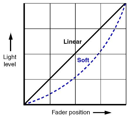
Table of Contents

1.   Safety........................................................................................................... 4
        Key to symbols ....................................................................................... 4
        GLP Service and Support ..................................................................... 5
2.   JDC Line 500 overview .............................................................................. 6
3.   Features ....................................................................................................... 7
       JDC Line 1000 ........................................................................................ 8
       Fixture setup ........................................................................................... 8
       Strobe effects ........................................................................................ 8
       Individual Cell Control .......................................................................... 8
       Shutter / intensity effects ...................................................................... 8
       Background Color ................................................................................ 9
       Dimming ............................................................................................... 10
       Duration ............................................................................................... 10
       Rate ...................................................................................................... 10
       Flash style ............................................................................................. 11
       White point .......................................................................................... 11
       CTC ....................................................................................................... 11
       Pixel mirror ............................................................................................ 11
       No-signal behavior ............................................................................. 12
       Fan Mode ............................................................................................ 12
       PWM frequency .................................................................................. 13
       Display mode ...................................................................................... 13
       Display orientation .............................................................................. 14
       Custom settings presets...................................................................... 14
       Fixture information .............................................................................. 14
       Manual control .................................................................................... 14
       Custom settings and reloading factory defaults ............................ 15
       Service .................................................................................................. 15
4.   Control menus and onboard display .................................................... 16
       Quick menu ......................................................................................... 17
       Quick access options ......................................................................... 17
5.   Setting up the control protocol .............................................................. 18
6.   Control menu layout ............................................................................... 20
       Quick menu ......................................................................................... 23
7.   DMX control modes overview ................................................................ 24
8.   DMX control channel layout................................................................... 30
       DMX Mode 1: RGBW Strobe .............................................................. 31
       DMX Mode 2: W Strobe + RGB Strobe .............................................. 32
       DMX Mode 3: W Strobe + RGB Pixel ................................................. 35
       DMX Mode 4: White + RGB Strobes + W Pixel .................................. 38
       DMX Mode 5: Multipix ........................................................................ 41
       DMX Mode 6: Multipix Advanced .................................................... 43
       Control / Settings channel ................................................................. 45
www.glp.de
1. Safety
Key to symbols
The following symbols are used in the JDC Line 500 lighting fixture’s user
documentation:
Warning! Safety hazard. Warning! Hazardous voltage.
Risk of severe injury or Risk of lethal or severe
death. electric shock.
Warning! See user
manual for important Warning! Fire hazard.
safety information.
Warning! Risk of eye
injury.
Warning! Read the JDC Line 500 Quick Start and Safety Manual supplied with
the fixture and available for download from www.glp.de before installing,
operating or servicing the fixture. The Quick Start and Safety Manual
contains important information for the safe use of JDC Line 500 fixtures. If you
fail to read that information you may create a safety hazard with a risk of
injury, death or damage.
If you have any doubts or questions about how to use the GLP® JDC Line 500 lighting
fixture safely, contact your GLP supplier for assistance. Your GLP supplier will be happy
to help.
The user documentation for JDC Line 500 fixtures consists of three documents:
● The JDC Line 500 Quick Start and Safety Manual, supplied with JDC Line 500 fixtures
and available for download from www.glp.de. The Quick Start and Safety Manual
contains important safety information and installation instructions that the installer
and user must read. It also contains dimensions drawings and technical
specifications for the fixture.
● The JDC Line 500 User Manual, available for download from www.glp.de. The User
Manual explains features and control of JDC Line 500 fixtures.
● The JDC Line 500 DMX Channel Index, available for download from www.glp.de.
The Channel Index is a separate document containing the DMX control channel
layout and DMX commands available in the fixture. This information is also included
in the User Manual.
The JDC Line 500 is intended for use by experienced professionals with the knowledge
and skills to set up, operate, and maintain high-powered, remotely controlled lighting
4 JDC Line 500 User ManualGerman Light Products®
equipment safely and efficiently. These operations require expertise that may not be
provided in this manual.
● Respect all warnings and directions given in the fixture’s user documentation and
on the fixture. Read the fixture’s Quick Start and Safety Manual and familiarize
yourself with the safety precautions it contains before installing, using or servicing the
fixture. GLP and affiliated companies will take no responsibility for damage or injury
resulting from disregard for the information in the user documentation.
● Check the GLP website at www.glp.de and make sure that you have the latest
versions of the fixture’s Quick Start and Safety Manual and this user manual.
● Check the fixture software version indicated on page 2 of this user manual and then
use the fixture’s control panel to check the version installed in the fixture. If the
versions are not the same, the user manual may still cover the fixture, because
software updates do not always affect the use of the fixture. However, it is possible
that this manual does not match the fixture perfectly. Software release notes can
help clarify this question. You can consult software release notes and download the
correct version of this user manual on the GLP website if necessary.
● Make both the Quick Start and Safety Manual and this user manual available to all
persons who will install, operate or service the fixture. Save both documents for
future reference.
● If you have any questions about the safe operation of the fixture, please contact an
authorized GLP distributor (see list of distributors at www.glp.de).
GLP Service and Support
Contact information for the nearest GLP Service and Support is available online at
www.glp.de/en/service, by email at info@glp.de, or by telephone at the following
numbers:
● GLP Germany: +49 (7248) 927 19-55
● GLP N. America: +1 818 767-8899
● GLP UK: +44 1392 690140
● GLP Asia: +852 (3151) 7730
● GLP Nordic: +46 737 57 11 40
Rev. 20210318-02 5www.glp.de
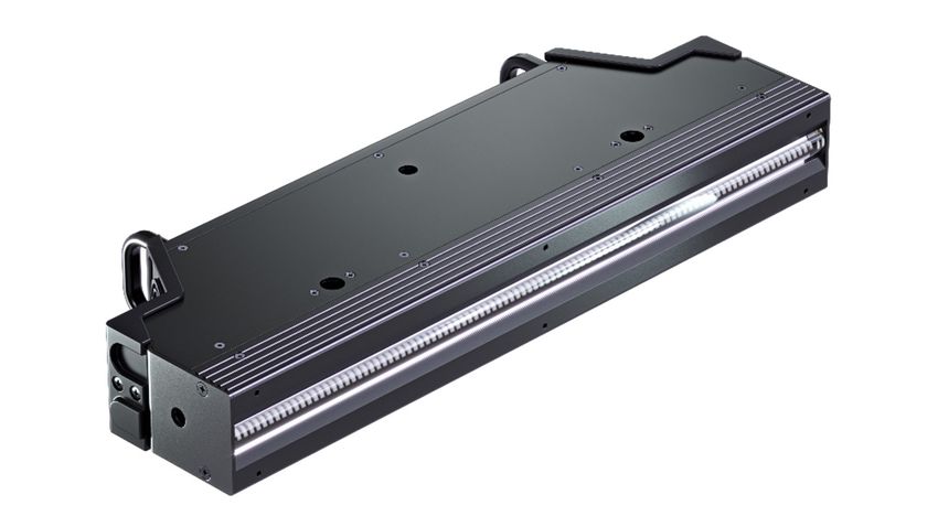
2. JDC Line 500 overview
B C G H I
A A
D D
E F J K
N
O
M
N
Q
P
Figure 1. JDC Line 500 overview
L
A – End bracket / side-to-side J – DMX OUT/THRU (5-pin XLR)
alignment points
K – Network port B (EtherCON),
B – Network port A (EtherCON), failsafe
failsafe)
L – 2 x End mounting points
C – DMX IN (5-pin XLR) (M10 threaded, depth 16 mm)
D – Air vent M – 2 x Safety cable attachment
points / carrying handles
E – AC mains power IN
(Neutrik powerCON TRUE1) N – Top / bottom mounting points
(M10 threaded, depth 16 mm)
F – Fuseholder
O – Quarter-turn fastener point
G – Main cooling fan
P – White LEDs, RGB LEDs
H – Control panel with multi-color
backlit LED display Q – 6 x M4 threaded holes for
permanent mounting of
I – AC mains power OUT/THRU
accessories
(Neutrik powerCON TRUE1)
6 JDC Line 500 User ManualGerman Light Products®
3. Features
The JDC Line 500 from GLP® is a powerful LED-based strobe/color effect linear lighting
fixture. It combines a powerful strobe line with RGB and white pixel mapping in one
device. It features:
● 20 super-bright White strobe segments
● 20 super-bright RGB segments
● RGB segments can be split into two (40 segments total) for even more zig-zag
effects
● White, RGBW and RGB strobes
● White and RGB pixel mapping, White strobe over RGB pixel mapping, and RGB
strobe over White pixel mapping
● RGBW background channels with separate dimmer for continuous ambient light
● Powerful FX engines with a range of pre-programmed pixel patterns
● Interlocking design that allows almost gapless installation of multiple fixtures
● Rear airflow design that lets you stack fixtures on top of each other or place them
directly on the ground
● Ease of installation with smart, flexible rigging and mounting options
● Control panel with new backlit multicolor LED display
● Quarter-turn locking points for omega clamps and end-to-end fastener bars
● Integration with JDC Line 1000 fixture
The JDC Line 500 features a central tube of 100 x powerful White LEDs in 20 segments
that provide impressive strobe effects and pixel mapping. Above and below the White
LEDs are 200 x RGB LEDs in two rows that can be controlled as 20 or 40 segments. The
RGB LEDs also provide strobe effects and pixel mapping.
A range of pre-programmed dynamic FX patterns with variable parameters can be
selected and run on the White and RGB segments.
The JDC Line 500 can be used indoors in permanent and temporary installations. It can
be placed horizontally on a level surface, suspended from a suitable rigging structure
or mounted on a structure or surface as described in the fixture’s Quick Start and
Installation Manual.
Fixtures can be interlocked in lines, and power and data can be daisy-chained for
ease of installation.
A magnetic system lets you mount optical accessories from GLP on the front of the
fixture in seconds. Six M4 threaded holes are provided for more permanent installation
of optical accessories.
The JDC Line 500 is not suitable for household use, for use in any location where
unattended children have access to it, or for use in permanent outdoor installations.
Rev. 20210318-02 7www.glp.de JDC Line 1000 The JDC Line Series includes the JDC Line1000, which is twice the length and has twice the performance of the JDC Line 500. The JDC Line1000 has the advantage that it only requires one power connection, one data connection and one control panel to run 1000 mm of JDC Line fixture. Internally, the JDC Line 1000 has two separate strobe and effect engines, which lets you operate it as if it was two separate 500 mm fixtures. The DMX channel layout of the JDC Line1000 is based on the layout of 2 x JDC Line 500s. This means that you can simply patch two JDC Line 500s next to each other to control one JDC Line 1000. The Control / Settings channel of the second patched fixture is ignored – the JDC Line 1000 uses the Control / Settings channel of the first patched fixture only. Fixture setup The JDC Line 500 has an onboard control panel with a graphic display (see ‘Control menus and onboard display’ on page 16) that you can use to configure the fixture’s settings. You can also access all the fixture’s important settings remotely via DMX on the fixture’s Control / Settings channel (DMX channel 6 in all DMX modes). Strobe effects The JDC Line 500 features RGBW strobe effects that you can run on all the fixture’s LEDs together over a background with RGBW control. It also offers RGB and White strobe effects that you can run separately. Again, you can run White and RGB strobe effects over a background with RGBW control. All strobe effects feature a powerful effects engine with pre-programmed patterns. You can snap between patterns and between steps in patterns, or you can crossfade with variable fade times. Individual Cell Control Some of the control modes provide individual control of the white or RGB segments. On the JDC Line 500 the line of powerful White LEDs can be split into 20 segments. The line of powerful RGB LEDs can also be split into 20 segments with the additional possibility of separating the top and bottom half of each segment to give individual control of 40 RGB pixels. The JDC Line1000 offers 2 x 20 White and RGB segments that can be controlled like 2 x JDC Line 500s. For normal pixel-mapping applications (MultiPix Mode) the upper and lower half of each RGB Segment are controlled at the same time. Advanced pixel-mapping mode (MultiPix Advanced Mode) allows individual control of the top and bottom part of the pixel. RGB Pattern selection offers both segment Patterns and split-segment patterns. Shutter / intensity effects The JDC Line 500’s electronic shutter effect provides single flash, pulse, opening pulse, closing pulse, random pulse, random opening pulse, random closing pulse, double 8 JDC Line 500 User Manual
German Light Products®

flash, random double flash, triple flash, random triple flash, spike, lightning, random
pixel flash and random fixture flash effects as well as instant blackout.

Background Color
All control modes offer a set of RGBW channels with a separate dimmer called
Background Color. By default these channels should be set to 0% because they are
not necessary for normal use of the fixture.
The Background Color channels let you add a low-priority background color, giving
you the ability to set a continuous background color for ambient light in the set design,
for example. You can add any of the fixture’s other effects on top of the background
color at any time.
Background Color works as in these two examples:
● No Background Color active - Background Color is set to 0%.
  You can use the main fixture as normal, but all flash effects run on top of a “black”
  background. The intervals between flashes are black (off).
● Background Color active - Background Color is set to Blue 100%.
  You can use the main fixture as normal, for example red flashes, but all flash effects
  run on top of a blue background. This gives red flashes with blue in-between the
  flashes.

Background color and main color mixing
You can define how the background color and the main fixture color are mixed. There
are three options:
   Crossfade (default) – the Background Color stays in the background and the main
   color has higher priority. If you fade in a main color, the background color will
   crossfade to the main color. For example, if you set a blue background color and
   then fade in continuous red on the main color channels you will obtain a crossfade
   from blue background to red main color.
   Mix – the Background Color mixes with the main color. For example, if you set a
   blue background color and then run a red Flash on the main color channels, the
   result will be a magenta flash. The main color of the flash will mix with the
   background color.
   Override – the Background Color stays in the background. The color displayed
   using the main channels has higher priority and will not mix with the background
   color. As soon the main color value is >0 the background color will black out and
   the main color will appear. For example, if you set a blue background color and
   then fade in continuous red on the main color channels, the blue will disappear
   completely and the red will fade up from zero intensity. The main red color will not
   mix or crossfade with the background blue color.
You can select the Crossfade, Mix or Override options in the Fixture Settings menu in
the fixture’s control panel, on the Control / Settings DMX channel, or via RDM.

                                    Rev. 20210318-02                                       9
www.glp.de
Dimming
The Dimmer channels control the output of the fixture in 16-bit resolution. You can
select from Linear or Soft dimming curves in the Fixture Settings menu in the fixture’s
control panel, on the Control / Settings DMX channel, or via RDM.
See Figure 2. The dimming curve options available are:
● Linear - the Linear setting gives a dimming curve that the eye perceives as linear.
Intensity appears to increase and decrease evenly throughout the dimming range.
● Soft - The Soft (square law) setting gives finer control at lower light levels, where the
eye is most sensitive to changes in light intensity, and coarser control at higher light
levels.
The default dimming curve is Soft.
Figure 2. Dimming curves
Duration
The Flash Duration channel lets you adjust the length of flashes from super-short to long.
Rate
If no intensity effect is selected, the Flash Rate channel lets you adjust the interval
between flashes:
● At DMX values from 000 to 004 the fixture will not flash.
● At DMX values from 251 to 255 the fixture will execute a continuous on.
● At DMX values from 005 to 250 the fixture will perform flashes with long intervals to
super-short intervals between flashes.
If an intensity effect is selected, the Flash Rate channel lets you adjust the speed of the
intensity effect.
10 JDC Line 500 User ManualGerman Light Products®
Flash style
The JDC Line 500 offers two types of LED behavior when operating as a strobe:
● Normal sets LEDs to light continuously during flashes at the PWM rate set using the
control panel (the default rate is 3000 Hz)
● Xenon sets LEDs to mimic the high-frequency flicker during flashes that is
characteristic of xenon tube strobe lights.
You can change the Flash style setting in the Fixture Settings menu in the fixture’s
control panel, on the Control / Settings DMX channel, or via RDM.
White point
This setting lets you select the white point obtained when RGB is set to 100% and obtain
a clean white light with fixed white point when opening the fixture’s shutter without
adjusting RGB color or programming color presets. The following color temperatures
are available as fixed white points: 8000 K, 6500 K and 5600 K. The default setting is
6500 K.
Setting White point to Off disables this feature and puts RGB control into raw mode.
You can change the White point setting in the Fixture Settings menu in the fixture’s
control panel, on the Control / Settings DMX channel, or via RDM.
CTC
Using the CTC (Color Temperature Correction) channel lets you temporarily leave the
fixed white point of the fixture and change it within a color temperature range of 10
000 K to 2 500 K.
Note that RGB needs to be set to 100% to mix pure white. Decreasing RGB values will
modify the color relative to the chosen CTC white point.
Pixel mirror
To achieve symmetrical effects in multiple installations or co-ordinate effects when
fixtures are not oriented identically, the JDC Line 500 lets you quickly reverse and/or
invert the order of its pixels:
● Off gives normal pixel layout (see Figure 3). Pixel 01 is at the Power OUT/THRU end of
the fixture, on the left when facing the fixture with the fixture oriented normally.
RGB
01 02 03 04 05 06 07 08 09 10 11 12 13 14 15 16 17 18 19 20
Upper
White 01 02 03 04 05 06 07 08 09 10 11 12 13 14 15 16 17 18 19 20
RGB
21 22 23 24 25 26 27 28 29 30 31 32 33 34 35 36 37 38 39 40
Lower
Figure 3. Normal pixel layout
● X-mirror reverses the order of the pixels so that they run from right to left. In this
configuration, Pixel 01 is at the Power IN end of the fixture, on the right when facing
the fixture with the fixture oriented normally.
Rev. 20210318-02 11www.glp.de
● Y-mirror inverts the RGB pixel rows so that the pixels run from left to right but pixels 11
to 20 move to the top row and pixels 1 to 10 move to the bottom row of the fixture.
Top and bottom are relative to the control panel display when the display
orientation is set to Normal.
● X-Y-mirror reverses the order of the pixels and inverts the RGB pixel rows at the same
time.
You can change the Pixel mirror setting on the Control / Settings DMX channel, in the
Fixture Settings menu in the fixture’s control panel.
No-signal behavior
You can decide how the fixture should behave if it is not receiving a DMX signal (if the
fixture is being controlled by DMX but the DMX signal stops, or if you apply power to
the fixture when no DMX signal is present). Three options are available:
● Blackout – The fixture goes to dead blackout. This is the default setting.
● Hold – The fixture holds the last DMX values that it received.
● Houselight – The fixture switches to the maximum light level that can be displayed
continuously.
These settings are available on the Control / Settings DMX channel, in the Fixture
Settings menu in the fixture’s control panel, or via RDM.
To avoid any possibility of unexpected behavior from a powerful strobe light if the DMX
signal fails, we recommend that you always set the fixture to Blackout or Houselight.
Fan Mode
The Fan Mode setting gives different options for the fixture’s cooling fan operation and
temperature management. Having options to choose from can be very helpful if you
are operating the fixture in a very hot or noise-sensitive environment. Four options are
available:
● Regulated – gives priority to light output and only operates fans as necessary. If the
fixture is blacked out, fans run at minimum speed. When light output intensity is
increased, temperature regulation increases fan speed to the level necessary to
keep the fixture at optimum temperature.
If light output is set to maximum intensity but the fans can keep the fixture at
optimum temperature, there will be no regulation of light intensity. If the fixture
begins to exceed optimum temperature and fans are running at maximum speed it
will begin to limit light intensity until optimum temperature can be maintained.
● High – lets the fixture operate at maximum light output and suits operation in high
ambient temperatures. Fans are set to constant operation at high speed. Light
output intensity is limited smoothly if it becomes necessary in order to keep fixture
temperature at optimum temperature level.
Besides maximizing light output in high ambient temperatures, you can use this
mode to cool down a fixture quickly or to remove dust from cooling fans.
12 JDC Line 500 User ManualGerman Light Products®
● Medium – sets fans to constant operation at medium speed. Light output intensity is
reduced to a level where it will normally remain constant at ambient temperatures
of up to 45° C (113° F). Intensity is smoothly limited further if it becomes necessary in
order to keep fixture temperature at optimum temperature level.
● Low – sets fans to constant operation at low speed and is optimized for minimum
noise. Light output intensity is reduced to a level where it will normally remain
constant at ambient temperatures of up to 30° C (86° F). Intensity is smoothly limited
further if it becomes necessary in order to keep fixture temperature at optimum
temperature level.
In all fan modes, if fixture temperature reaches a dangerous level, LEDs will be shut
down for a period until the fans have brought the temperature down to a safe level.
PWM frequency
You can change the LED dimming PWM frequency in order to avoid flicker and beat
frequencies in video images. To do this, select a new PWM frequency using either the
Control / Settings DMX channel, the Fixture Settings menu in the fixture’s control panel
or RDM.
The default PWM setting is 3000 Hz. You can set the PWM frequency to 2200 Hz,
3000 Hz, 4800 Hz or 9600 Hz. Note that a higher PWM frequency may affect dimming
performance.
The PWM frequency setting is stored in the fixture and is not affected by cycling power
off and on. However, it will be reset to the default frequency if you apply a Fixture
Settings Load Settings Default command or a Service Advanced Load
Factory Backup command in the control menus.
As a rule, you should set all the fixtures in an installation to the same PWM frequency in
order to ensure the same performance.
Display mode
You can choose between three different modes for the control panel display:
● Auto: The display will automatically switch off after a few seconds if the fixture is
receiving a valid control signal and has not detected an error. If the fixture is not
receiving a valid control signal the display will flash. If the fixture has detected an
error, the display will remain constantly on and show the error.
● On: The display stays on constantly. This setting can be useful when you are
configuring or servicing the fixture.
● Off: The display will automatically switch off after a few seconds even if the fixture is
not receiving a valid control signal or if it has detected an error.
The default setting is Auto.
You can change the Display mode setting on the Control / Settings DMX channel, in
the Fixture Settings menu in the fixture’s control panel, or via RDM.
Rev. 20210318-02 13www.glp.de Display orientation Depending on which way up you install the fixture, you can change the orientation of the control panel display: ● Auto: The readout in the display is automatically turned through 180° if the fixture is installed upside-down. ● Normal: The readout in the display is the right way up when the fixture is placed with the display closer to the right-hand end of the fixture, close to the Mains Power OUT/THRU connector, as shown in Figure 1 on page 6. ● Inverted: The readout in the display is turned through 180°. You can change the Display orientation setting on the Control / Settings DMX channel, in the Fixture Settings menu in the fixture’s control panel, or via RDM. Custom settings presets The JDC Line 500 sets you set up three different fixture configurations and save them as custom presets. A configuration includes all of the fixture’s personality settings (dimming curve, pixel orientation etc.) but does not include DMX address, DMX mode and control protocol type. Calling up a preset let you quickly recall configurations that you have set up in advance to match different uses or different environments. You can save custom presets and load custom presets via DMX on the Control / Settings DMX channel. You can also save custom presets in the Service Advanced Save Settings menu and load custom presets in the Fixture Settings menu in the fixture’s control panel. Fixture information The Information menu in the control panel gives access to items of information from the fixture’s sensors and memory. You can check temperature sensor readouts, see total operating hours counters and power cycle count, and see DMX signal quality data, for example. Manual control If the JDC Line 500 is connected to mains power you can control it without using a DMX controller if you open the Manual Control menu in the control panel. This menu also lets you reboot the fixture. If the fixture is connected to a DMX controller, it is also possible to take a snapshot of all the DMX values that the fixture is receiving using a Capture DMX Values command. These values are then applied as manual control values and stored in memory. Each time that you enter the Manual DMX menu, the fixture will use these values until you adjust them or apply a Reset Manual Values command. 14 JDC Line 500 User Manual
German Light Products®
Custom settings and reloading factory defaults
Custom settings are stored after a power off/on cycle and after a reset.
Two options are available in the fixture’s control panel for deleting multiple custom
settings and restoring defaults:
● Fixture Settings Load Settings Default reloads all the fixture’s factory default
settings except DMX address, DMX mode and Control protocol. This option returns
the fixture to baseline settings (Normal pixel orientation, Linear dimming curve, etc.)
without affecting its basic configuration in an installation.
● Service Advanced Load Factory Backup reloads all the fixture’s factory default
settings including DMX address, DMX mode and Control Protocol. This option
reinitializes the fixture completely and returns to its state when it left the factory.
Service
The Service menu is split into two levels: Service and Service Advanced.
The Service Advanced level is for trained technicians only. Read the User Manual
carefully before entering this level.
Test Sequences
This menu lets you run different test sequences in order to quickly check the product
for correct operation.
Reset Counters
The commands in this menu let you reset the fixture’s user resettable counters.
Note that device counters are not reset if you execute a Load Factory Backup
command.
Rev. 20210318-02 15www.glp.de
4. Control menus and onboard display
Warning! DMX control is disabled when the control menus are active. Be
prepared for the fixture to emit strong light as soon as you exit the control
menus.
The control panel and onboard backlit LED display provide access to user settings,
readouts and utilities.
1.0.0//M1 Main Menu
DMX Address
DMX Control Mode
QUICK UP UP
001
BACK
MENU Protocol Setup
Fixture Setup
(1…16) Information
Manual Control
MENU DOWN ENTER DOWN
Figure 5. Default screen Figure 4. Main menu
The functions of the control buttons depend on which screen is open in the control
panel display. The functions are indicated by icons:
BOTTOM-LEFT BUTTON (MENU / ENTER)
When the display is in sleep mode, the bottom-left MENU / ENTER button activates the
display and calls up the default screen (see Figure 5) that gives the following
information:
- Firmware version // DMX Mode
- Protocol type (DMX, Art-Net, sACN)
- DMX address
- DMX channel footprint.
When the default screen is active, the MENU / ENTER button ≡ opens the main menu
(see Figure 4).
When navigating in the menus, the MENU / ENTER button confirms a selection,
enters a sub-menu or implements a command.
TOP-LEFT BUTTON (QUICK MENU / BACK)
When the default screen is active, the QUICK MENU / BACK button » opens the quick
menu.
When navigating in the menus, the QUICK MENU / BACK button navigates back one
level towards the top of the menu.
TOP-RIGHT BUTTON (UP)
Scroll up through a menu or increase a number.
BOTTOM-RIGHT BUTTON (DOWN)
Scroll down through a menu or decrease a number.
16 JDC Line 500 User ManualGerman Light Products®
When you apply power to the fixture it takes a few seconds to boot. After it has
booted, the panel displays the default screen.
DMX control is disabled when the control menus are active.
A number of options for customizing the onboard display are available on the DMX
Control / Settings channel and in the Display control menu in the control panel.
Quick menu
A quick menu is provided to save time. To open the quick menu, activate the default
screen by pressing the MENU button and then press the ENTER button ».
The quick menu gives you the following options:
● Toggle the display orientation between auto, normal and inverted.
● Reboot the fixture.
● Load any of the three custom setting presets that have been saved previously or
load the factory default settings.
● Reinitialize the fixture by returning all settings to factory defaults, deleting all custom
presets, returning all resettable counters to zero, setting the fixture’s DMX address to
1 and setting the DMX Mode to the factory default (Mode 2: W Strobe + RGB
Strobe).
Quick access options
When the fixture is connected to mains power and has booted normally, the following
functions can be accessed quickly by pressing key combinations.
● Holding UP and DOWN pressed together for less than one second toggles the
display orientation.
● Pressing UP or DOWN three times calls up a readout of the main fixture information
and the fixture’s settings.
Battery Eco mode
When the fixture is not connected to mains power and is running on its internal battery,
holding MENU and ENTER pressed in together for 10 seconds activates Battery Eco
Mode. This disables battery power to protect the battery from being run flat if the
fixture is accidentally switched on during transportation.
Put the fixture into Battery Eco Mode before transportation or long-term storage.
To take the fixture out of Battery Eco Mode, simply connect it to power.
Rev. 20210318-02 17www.glp.de
5. Setting up the control protocol
The JDC Line 500 can be controlled via USITT512 DMX over a standard DMX cable link
using the fixture’s 5-pin XLR connectors or via Art-Net or sACN over network cable using
the fixture’s Ethernet port. This section explains how to configure the fixture to use the
control data protocol that it is connected to.
The fixture is set up for control via a standard DMX cable link by default.
DMX
To configure the fixture to receive DMX control data over a standard DMX cable link,
open the menus in the fixture’s control panel and make the following adjustments:
In the first menu (root menu), give a suitable DMX address to the fixture.
In the Protocol Setup Protocol Type menu, set the control protocol to DMX (the
default setting).
These settings will not be affected if you apply a Load Settings command in the
fixture’s control panel, but the DMX address will be returned to 1 (the factory default) if
you apply a Load Factory Backup command in the fixture’s control panel.
Art-Net
To configure the fixture to receive DMX control data via Art-Net, open the menus in the
fixture’s control panel and make the following adjustments:
In the first menu (root menu), give a suitable DMX address to the fixture.
In the Protocol Setup Protocol Type menu, set the control protocol to Art-Net.
Give all fixtures their own unique IP addresses. To do this, you can either:
● set fixtures to generate their own IP addresses by choosing the ranges 2.x.x.x or
10.x.x.x (Art-Net specification),
● set fixtures to acquire IP addresses automatically by DHCP, or
● assign IP addresses manually by entering individual IP addresses and Subnet mask.
Select an Art-Net port/universe from 00000 (Network 0 / Subnet 0 / Universe 0) to
32767 (Network 7 / Subnet 15 / Universe 255). Note that the first Art-Net universe is
considered to be universe number 00000, not 00001.
These settings will not be affected if you apply a Load Default Settings command in the
fixture’s control panel, but they will be returned to factory defaults if you apply a Load
Factory Backup command in the fixture’s control panel.
Note that it is possible to transmit DMX data as broadcast or unicast packages via Art-
Net. If a large number of universes (more than 30) is broadcast, data loss can occur. If
you suspect that this is happening, configure your console to unicast Art-Net DMX
packages to fixtures, or switch to sACN.
18 JDC Line 500 User ManualGerman Light Products®
sACN
To configure the fixture to receive DMX control data via sACN, open the menus in the
fixture’s control panel and make the following settings:
In the first menu (root menu), give a suitable DMX address to the fixture.
In the Protocol Setup Protocol Type menu, set the control protocol to sACN.
Give all fixtures their own unique IP addresses. To do this, you can either:
● set fixtures to generate their own IP addresses by choosing the ranges 2.x.x.x or
10.x.x.x (Art-Net specification),
● set fixtures to acquire IP addresses automatically by DHCP, or
● assign IP addresses manually by entering individual IP addresses and Subnet mask.
Select an sACN universe from 00001 to 63999.
These settings will not be affected if you apply a Load Default Settings command in the
fixture’s control panel, but they will be returned to factory defaults if you apply a Load
Factory Backup command in the fixture’s control panel.
Rev. 20210318-02 19www.glp.de
6. Control menu layout
Menus Notes
DMX Address
1 - 512 Enter DMX address
Control Mode
M1 – RGBW Strobe (CH14)
M2 - WStrobe + RGBStrobe (CH32)
M3 - WStrobe + RGBPixel (CH82)
Select DMX control mode
M4 - RGBStrobe + WPixel (CH45)
M5 - MultiPix (CH96)
M6 - MultiPix Advanced (CH156)
Protocol Setup
DMX Control via DMX protocol
Protocol type ArtNet Control via Art-Net protocol
sACN Control via sACN protocol
Auto addressing in the range
Auto 2.X.X.X
2.X.X.X
Auto addressing in the range
Auto 10.X.X.X
10.X.X.X
Addressing Mode Uses custom IP address and custom
Static IP subnet mask (set these in next
menu)
Ethernet Config
DHCP Gets IP address by DHCP
Custom IP Address xxx.xxx.xxx.xxx Enter custom IP address
Custom IP Subnet xxx.xxx.xxx.xxx Enter custom subnet mask
0 - 32768 Sets which port listens for sACN
ArtNet Port
packets
sACN Universe 1 - 63999 Sets ACN universe
Fixture Settings
Linear
Dimmer Curve Select dimming curve
Soft
Normal Normal strobe
Flash Style
Xenon Simulated xenon flicker strobe
8000 Sets white point to 8000 K
6500 Sets white point to 6500 K
White point
5600 Sets white point to 5600 K
Off (RAW) Raw white control
20 JDC Line 500 User ManualGerman Light Products®
Normal pixel order: 1 to 10
Off
(Pixel 1 is at Power IN)
Reversed pixel order: 10 to 1
x-mirror
(Pixel 1 is at Power OUT)
Pixel Mirror
Inverted pixel order
y-mirror
(Pixel 11 to 20 on top row)
Reversed and inverted pixel order
x-y-mirror
(Pixel 20 to 11 on top row)
Crossfading from background
Crossfade
color to main color
Main color mixes with background
Background Mix
color
Main color completely overrides
Override
background color
If DMX signal absent, fixture blacks
Blackout
out
If DMX signal absent, fixture holds
No Signal Hold
last DMX values received
If DMX signal absent, fixture goes to
Houselight
constant white light
Regulated Fan speed regulated
Fans run at constant high speed,
High
output reduced if necessary
Fan Mode Fans run at constant medium
Medium speed, output reduced if
necessary
Fans run at constant low speed,
Low
output reduced if necessary
2200 Hz
3000 Hz
PWM Frequency Sets LED refresh rate
4800 Hz
9600 Hz
Control panel display enters sleep
Auto mode after short period. An error
will cause the display to light up.
Display Mode Display constantly on
On
Display constantly off. An error will
Off
not cause the display to light up.
Control panel display
Auto automatically inverts if fixture is
Display Orientation inverted
Normal Display normal
Inverted Display inverted down to up
Preset 1 Hold 3 sec.
Loads custom settings and custom
Preset 2 Hold 3 sec.
offsets
Load Settings Preset 3 Hold 3 sec.
Loads factory default settings and
Default Hold 3 sec.
offsets
Information
Show Errorlist Shows last and current errors
Show Serial Number Shows fixture’s serial number
Show SW version Shows current software version
Show device info Shows fixture information
Shows resettable and non-
Show device hours
resettable counters
Rev. 20210318-02 21www.glp.de
Shows resettable and non-
Device Power Cycles
resettable power cycle counters
Shows DMX values received for all
Show DMX Input
functions
Shows signal quality (framerate,
Show Signal Quality
noise, etc.)
Show Temperature Shows temperatures in °C & °F
Show Fan Monitor Shows fan rpm and Voltage
Manual Control
Reboot (confirm 3 sec.) Reboots fixture
Intensity coarse
000 - 255
(RGBW)
Intensity fine (RGBW) 000 - 255
Duration (RGBW) 000 - 255
Rate (Shutter)
000 - 255
(RGBW)
Intensity Effects
Manual fixture control
[Strobe Mode] 000 - 255
(RGBW)
Manual DMX CTC 000 - 255
R 000 - 255
G 000 - 255
B 000 - 255
W 000 - 255
Takes a snapshot of DMX values
Capture DMX values (confirm 3 sec.) currently being received and uses
them as manual DMX values
Resets all manual DMX values to
Reset Manual values (confirm 3 sec.)
default
Service
Runs continuous test sequence:
pan & tilt first, then all FX with head
Test All Confirm
straight up. Stop test by pressing
"Back" button.
Runs continuous test sequence on
Test White Confirm White LEDs. Stop test by pressing
"Back" button.
Runs continuous test sequence on
Test RGB Confirm RGB LEDs. Stop test by pressing
"Back" button.
Device Hours (confirm 3
sec.)
Device Power Cycles
Reset Counters Returns resettable counter to zero
(confirm 3 sec.)
Max Temperatures
Advanced (confirm 3 sec.)
(Press and Preset 1 (confirm 3 sec.)
hold Enter for Saves all custom settings including
Save Settings Preset 2 (confirm 3 sec.)
3 sec. to offsets as a preset
Preset 3 (confirm 3 sec.)
confirm) Loads factory default settings,
resets custom offsets, deletes
custom presets, sets resettable
Load factory backup (confirm 5 sec.)
counters to zero, sets DMX address
to 1, sets DMX mode to default
(Mode 2: WStrobe + RGBStrobe)
Default settings are written in BOLD type.
22 JDC Line 500 User ManualGerman Light Products®
Quick menu
To open the quick menu, press the ENTER button: [>>] symbol
Menus Notes
Display automatically inverts if
Auto
fixture is inverted
Display Orientation Normal Display normal
Inverted Display inverted down to up
Reboot Confirm Reboots fixture
Preset 1 Hold 3 sec.
Load custom settings and custom
Preset 2 Hold 3 sec.
offsets
Load Settings Preset 3 Hold 3 sec.
Loads factory default settings and
Default Hold 3 sec.
offsets
Loads factory default settings,
resets custom offsets, deletes
customer presets, sets resettable
Load Factory Backup (!) – confirm for 5 sec.
counters to zero, sets DMX address
to 1, sets DMX mode to default
(Mode 2: WStrobe + RGBStrobe)
Rev. 20210318-02 23www.glp.de
7. DMX control modes overview
The following DMX control modes are available in the JDC Line 500.
DMX Mode 1: RGBW Strobe
Mode 1
14 DMX Channels RGBW Strobe
RGBW strobe is a global strobe that RGBW strobe
1 Intensity coarse
uses all the White and all the RGB
2 Intensity fine
segments together. The strobe has 3 Duration
flash, pulse and ramp-up/down effects 4 Flash rate (Shutter)
as well as special intensity effects such 5 Intensity effects (Strobe mode)
as lightning. It offers RGBW control plus 6 Control / Settings
separate color temperature control 7 CTC
that defines the fixture’s white point. 8 Red
9 Green
Background color sets a background 10 Blue
color on the RGB segments. As 11 White
standard, the main color output always Background color
has higher priority than the 12 Intensity background
background color. The way that 13 Red background
background color and main color are 14 Green background
mixed can be selected using 15 Blue background
Background color on the 16 White background
Control/Settings channel.
Control / Settings lets you configure the
fixture remotely via DMX.
24 JDC Line 500 User ManualGerman Light Products®
Mode 2
DMX Mode 2: W Strobe + RGB Strobe W Strobe + RGB Strobe
34 DMX channels White strobe with FX
1 Intensity coarse
White strobe with FX runs on the White
2 Intensity fine
segments only and has an effects 3 Duration
engine with 50 patterns. 4 Flash rate (Shutter)
RGB strobe with FX runs on the RGB 5 Intensity effects (Strobe mode)
6 Control / Settings
segments only and has its own effects
7 Pattern select
engine with 50 patterns. 8 Pattern step / speed
Both strobes let you control crossfading 9 Pattern step crossfading
10 Pattern transition
(duration of changes between the
11 Pattern chain length
steps in each pattern) and transition
12 Pattern chain position
(duration of changes from one pattern
to the next). RGB strobe with FX
13 Intensity coarse
Pattern chain length lets you set up a 14 Intensity fine
chain of fixtures for the pattern to run 15 Duration
across – it defines the total number of 16 Flash rate (Shutter)
fixtures in the chain. Pattern chain 17 Intensity effects (Strobe mode)
position lets you set which position in 18 CTC
19 Red
the chain the fixture will occupy: first,
20 Green
second or third etc. fixture in the chain. 21 Blue
Strobe phase lets you shift the timing of 22 Pattern select
23 Pattern step/speed
the RGB strobe by 1 – 359° relative to
24 Pattern step crossfading
the White strobe. A 180° shift will result 25 Pattern transition
in a flip-flop between white and RGB 26 Pattern chain length
flashes. 27 Position in chain
28 Strobe phase
Pattern phase lets you shift the timing
29 Pattern phase
of the RGB pattern by 1 – 359° relative
to the White pattern. Background color
30 Intensity background
Background color sets a background 31 Red background
color on the RGB segments. As 32 Green background
standard, the main color output always 33 Blue background
has higher priority than the 34 White background
background color. You can define
how background color and main color
are mixed using Background color on
the Control/Settings channel.
Control / Settings lets you configure the
fixture remotely via DMX.
Rev. 20210318-01 25www.glp.de
Mode 3
DMX Mode 3: W Strobe + RGB Pixel W Strobe + RGB Pixel
84 DMX Channels White strobe with FX
1 Intensity coarse
White strobe with FX runs on the White
2 Intensity fine
segments only and has an effects 3 Duration
engine with 50 patterns. Crossfading 4 Flash rate (Shutter)
sets the duration of changes between 5 Intensity effects (Strobe mode)
the steps in each pattern. Transition 6 Control / Settings
sets the duration of changes from one 7 Pattern select
pattern to the next. 8 Pattern step / speed
9 Pattern step crossfade
Pattern chain length lets you set up a 10 Pattern transition
chain of fixtures for the pattern to run 11 Pattern chain length
across in a chase by defining the total 12 Pattern chain position
number of fixtures in the chain. Pattern RGB segments overall control
chain position lets you set which 13 Intensity coarse
position in the chain the fixture will 14 Intensity fine
occupy: first, second or third etc. fixture 15 Duration
in the chain. 16 Flash rate (Shutter)
17 Intensity effects (Strobe mode)
RGB segments overall control gives 18 CTC
overall output control of the 19 Strobe phase
individually controllable RGB segments
Background color
at the end of this DMX mode (see
20 Intensity background
below). It offers the standard strobe 21 Red background
channels for intensity and strobe 22 Green background
effects and a CTC Channel which lets 23 Blue background
you adjust the color temperature of 24 White background
the white output. RGB segments individual control
Strobe phase lets you shift the timing of 25 Red segment 01
the RGB segments strobe by 1 – 359° 26 Green segment 01
27 Blue segment 01
relative to the strobe on the White
… …
segments. A 180° shift will result in a 82 Red segment 20
flipflop between flashes on the two 83 Green segment 20
strobes. 84 Blue segment 20
Background color sets a background
color on the RGB segments. As
standard, the main color output always RGB segments individual control adjusts
has higher priority than the the color of the individual RGB segments.
background color. You can define The output of these segments is
how background color and main color determined by the RGB segments overall
are mixed using Background color on control channels (see above).
the Control/Settings channel. The upper and lower halves of each
segment are controlled together, giving
20 RGB pixels.
Control / Settings lets you configure the
fixture remotely via DMX.
26 JDC Line 500 User ManualGerman Light Products®
Mode 4
DMX Mode 4: White + RGB Strobes + W White + RGB Strobes + W Pixel
Pixel
White segments overall control
47 DMX Channels 1 Intensity coarse
2 Intensity fine
White segments overall control gives 3 Duration
overall output control of the 4 Flash rate (Shutter)
individually controllable White 5 Intensity effects (Strobe mode)
segments at the end of this DMX mode 6 Control / Settings
(see below). It offers the standard RGB strobe with FX
strobe channels for intensity and strobe 7 Intensity coarse
effects. 8 Intensity fine
9 Duration
RGB strobe with FX provides an RGB
10 Flash rate (Shutter)
color strobe that runs on the RGB 11 Intensity effects (Strobe mode)
segments only. It has an effects engine 12 CTC
with 50 patterns. Crossfading sets the 13 Red
duration of changes between the 14 Green
steps in each pattern and transition 15 Blue
sets the duration of changes from one 16 Pattern select
pattern to the next. 17 Pattern step / speed
18 Pattern step crossfade
Pattern chain length sets up a chain of 19 Pattern transition
fixtures for the pattern to run across in a 20 Pattern chain length
chase – it defines the total number of 21 Position in chain
22 Strobe phase
fixtures in the chain. Position in chain
lets you set which position in the chain Background color
the fixture will occupy: first, second or 23 Intensity background
third etc. fixture in the chain. 24 Red background
25 Green background
Strobe phase lets you shift the timing of 26 Blue background
the RGB strobe by 1 – 359° relative to 27 White background
the White strobe. A 180° shift will result White segments individual control
in a flip-flop between flashes on the 28 White segment 01
two strobes. … …
47 White segment 20
Background color sets a background
color on the RGB segments. As
standard, the main color output always
has higher priority than the White segments individual control adjusts
background color. You can define the output of the individual White
how background color and main color segments. The overall output of these
are mixed using Background color on segments is determined by the White
the Control/Settings channel. segments overall control (see above).
Control / Settings lets you configure the
fixture remotely via DMX.
Rev. 20210318-01 27www.glp.de
Mode 5
DMX Mode 5: Multipix MultiPix
98 DMX Channels White segments overall control
1 Intensity coarse
White segments overall control gives
2 Intensity fine
overall output control of the 3 Duration
individually controllable White 4 Flash rate (Shutter)
segments at the end of this DMX mode 5 Intensity effects (Strobe mode)
(see below). It offers the standard 6 Control / Settings
strobe channels for intensity and strobe RGB segments overall control
effects. 7 Intensity coarse
RGB segments overall control gives 8 Intensity fine
9 Duration
overall output control of the
10 Flash rate (Shutter)
individually controllable RGB segments 11 Intensity effects (Strobe mode)
at the end of this DMX mode (see 12 CTC
below). It offers the standard strobe 13 Strobe phase
channels for intensity and strobe
Background color
effects and a CTC Channel which lets
14 Intensity background
you adjust the color temperature of 15 Red background
the white output. 16 Green background
17 Blue background
Strobe phase lets you shift the timing of
18 White background
the RGB segments strobe by 1 – 359°
relative to the strobe on the White White segments individual control
segments. A 180° shift will result in a 19 White segment 01
flipflop between flashes on the two … …
38 White segment 20
strobes.
RGB segments individual control
Background color sets a background 39 Red segment 01
color on the RGB segments. As 40 Green segment 01
standard, the main color output always 41 Blue segment 01
has higher priority than the … …
background color. You can define 96 Red segment 20
how background color and main color 97 Green segment 20
are mixed using Background color on 98 Blue segment 20
the Control/Settings channel.
White segments individual control The upper and lower halves of each RGB
adjusts the output of the individual segment are controlled together, giving
White segments. The overall output of individual RGB control of 20 RGB pixels in
these segments is determined by the total.
White segments overall control
channels (see above). Control / Settings lets you configure the
fixture remotely via DMX.
RGB segments individual control
adjusts the color of the individual RGB
segments. The output of these
segments is determined by the RGB
segments overall control channels (see
above).
28 JDC Line 500 User ManualGerman Light Products®
Mode 6
DMX Mode 6: MultiPix Advanced MultiPix Advanced
158 DMX Channels White strobe
1 Intensity coarse
White segments overall control gives
2 Intensity fine
overall output control of the 3 Duration
individually controllable White 4 Flash rate (Shutter)
segments at the end of this DMX mode 5 Intensity effects (Strobe mode)
(see below). It offers the standard 6 Control / Settings
strobe channels for intensity and strobe RGB strobe
effects. 7 Intensity coarse
RGB segments overall control gives 8 Intensity fine
9 Duration
overall output control of the
10 Flash rate (Shutter)
individually controllable RGB segments 11 Intensity effects (Strobe mode)
at the end of this DMX mode (see 12 CTC
below). It offers the standard strobe 13 Strobe phase
channels for intensity and strobe
Background color
effects and a CTC Channel which lets
14 Intensity background
you adjust the color temperature of 15 Red background
the white output. 16 Green background
17 Blue background
Strobe phase lets you shift the timing of
18 White background
RGB segments strobe by 1 – 359°
relative to the strobe on the White White segments individual control
segments. A 180° shift will result in a 19 White segment 01
flipflop between flashes on the two … …
38 White segment 20
strobes.
RGB segments individual control
Background color sets a background (upper, lower separately)
color on the RGB segments. As 39 Red segment 01
standard, the main color output always 40 Green segment 01
has higher priority than the 41 Blue segment 01
background color. You can define … …
how background color and main color 156 Red segment 40
157 Green segment 40
are mixed using Background color on
158 Blue segment 40
the Control/Settings channel.
White segments individual control
adjusts the output of the individual The RGB segments are split into upper
White segments. The overall output of and lower halves with individual control
these segments is determined by the of each half. This gives individual RGB
White segments overall control control of 40 RGB pixels in total.
channels (see above).
Control / Settings lets you configure the
RGB segments individual control fixture remotely via DMX.
(upper, lower) adjusts the color of the
individual RGB segments. The output of
these segments is determined by the
RGB segments overall control channels
(see above).
Rev. 20210318-01 29www.glp.de 8. DMX control channel layout In the following DMX channel layout tables: ● Default settings are indicated with bold type. ● Where commands are followed by (3s hold) you must send that value continuously for 3 seconds (or other duration if indicated in the table) to apply the command. ● Some commands on the Control / Settings channel require the DMX value zero to be sent first and then moved directly to the DMX value required by the command concerned. 30 JDC Line 500 User Manual
You can also read