Jupiter Rising: A Decade of Clos Topologies and Centralized Control in Google's Datacenter Network
←
→
Page content transcription
If your browser does not render page correctly, please read the page content below
Jupiter Rising: A Decade of Clos Topologies and
  Centralized Control in Google’s Datacenter Network

    Arjun Singh, Joon Ong, Amit Agarwal, Glen Anderson, Ashby Armistead, Roy Bannon,
  Seb Boving, Gaurav Desai, Bob Felderman, Paulie Germano, Anand Kanagala, Jeff Provost,
  Jason Simmons, Eiichi Tanda, Jim Wanderer, Urs Hölzle, Stephen Stuart, and Amin Vahdat
                                                                       Google, Inc.
                                                             jupiter-sigcomm@google.com

ABSTRACT                                                                                   abler for cloud computing. Bandwidth demands in the
We present our approach for overcoming the cost, oper-                                     datacenter are doubling every 12-15 months (Figure 1),
ational complexity, and limited scale endemic to dat-                                      even faster than the wide area Internet. A number of re-
acenter networks a decade ago. Three themes unify                                          cent trends drive this growth. Dataset sizes are continu-
the five generations of datacenter networks detailed in                                    ing to explode with more photo/video content, logs, and
this paper. First, multi-stage Clos topologies built from                                  the proliferation of Internet-connected sensors. As a re-
commodity switch silicon can support cost-effective de-                                    sult, network-intensive data processing pipelines must
ployment of building-scale networks. Second, much of                                       operate over ever-larger datasets. Next, Web services
the general, but complex, decentralized network rout-                                      can deliver higher quality results by accessing more data
ing and management protocols supporting arbitrary                                          on the critical path of individual requests. Finally, con-
deployment scenarios were overkill for single-operator,                                    stellations of co-resident applications often share sub-
pre-planned datacenter networks. We built a central-                                       stantial data with one another in the same cluster; con-
ized control mechanism based on a global configura-                                        sider index generation, web search, and serving ads.
tion pushed to all datacenter switches. Third, modu-                                          Ten years ago, we found the cost and operational
lar hardware design coupled with simple, robust soft-                                      complexity associated with traditional datacenter net-
ware allowed our design to also support inter-cluster                                      work architectures to be prohibitive. Maximum net-
and wide-area networks. Our datacenter networks run                                        work scale was limited by the cost and capacity of the
at dozens of sites across the planet, scaling in capacity                                  highest end switches available at any point in time [24].
by 100x over ten years to more than 1Pbps of bisection                                     These switches were engineering marvels, typically re-
bandwidth.                                                                                 cycled from products targeting wide area deployments.
                                                                                           WAN switches were differentiated with hardware sup-
CCS Concepts                                                                               port/offload for a range of protocols (e.g., IP multi-
                                                                                           cast) or by pushing the envelope of chip memory (e.g.,
•Networks → Data center networks;                                                          Internet-scale routing tables, off chip DRAM for deep
                                                                                           buffers, etc.). Network control and management pro-
Keywords                                                                                   tocols targeted autonomous individual switches rather
Datacenter Networks; Clos topology; Merchant Silicon;                                      than pre-configured and largely static datacenter fab-
Centralized control and management                                                         rics. Most of these features were not useful for datacen-
                                                                                           ters, increased cost, complexity, delayed time to market,
1.     INTRODUCTION                                                                        and made network management more difficult.
                                                                                              Datacenter switches were also built as complex chas-
  Datacenter networks are critical to delivering web ser-                                  sis targeting the highest levels of availability. In a
vices, modern storage infrastructure, and are a key en-                                    WAN Internet deployment, losing a single switch/router
                                                                                           can have substantial impact on applications. Because
                                                                                           WAN links are so expensive, it makes sense to invest in
Permission to make digital or hard copies of part or all of this work for personal
or classroom use is granted without fee provided that copies are not made or
                                                                                           high availability. However, more plentiful and cheaper
distributed for profit or commercial advantage and that copies bear this notice            datacenter bandwidth makes it prudent to trade cost
and the full citation on the first page. Copyrights for third-party components of          for somewhat reduced intermittent capacity. Finally,
this work must be honored. For all other uses, contact the owner/author(s).
                                                                                           switches operating in a multi-vendor WAN environment
SIGCOMM ’15 August 17-21, 2015, London, United Kingdom
                                                                                           with arbitrary end hosts require support for many pro-
© 2015 Copyright held by the owner/author(s).
                                                                                           tocols to ensure interoperability. In single-operator dat-
ACM ISBN 978-1-4503-3542-3/15/08.
DOI: http://dx.doi.org/10.1145/2785956.2787508

                                                                                     183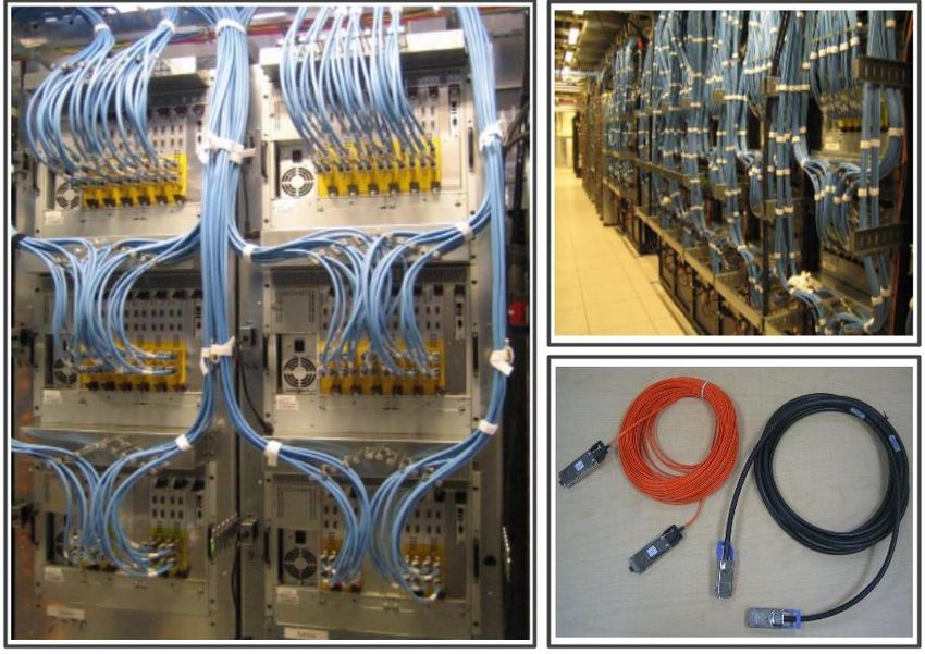
acenter deployments, the number of required protocols
can be substantially reduced.
   Inspired by the community’s ability to scale out com-
puting with parallel arrays of commodity servers, we
sought a similar approach for networking. This paper
describes our experience with building five generations
of custom data center network hardware and software
leveraging commodity hardware components, while ad-
dressing the control and management requirements in-
troduced by our approach. We used the following prin-
ciples in constructing our networks:
   Clos topologies: To support graceful fault tol-                 Figure 1: Aggregate server traffic in our datacenter fleet.
erance, increase the scale/bisection of our datacenter
networks, and accommodate lower radix switches, we
adopted Clos topologies [2, 9, 15] for our datacenters.
Clos topologies can scale to nearly arbitrary size by
adding stages to the topology, principally limited by
failure domain considerations and control plane scala-
bility. They also have substantial in-built path diversity
and redundancy, so the failure of any individual ele-
ment can result in relatively small capacity reduction.
However, they introduce substantial challenges as well,
including managing the fiber fanout and more complex
routing across multiple equal-cost paths.
   Merchant silicon: Rather than use commercial                    Figure 2: A traditional 2Tbps four-post cluster (2004). Top
switches targeting small-volume, large feature sets, and           of Rack (ToR) switches serving 40 1G-connected servers
high reliability, we targeted general-purpose merchant             were connected via 1G links to four 512 1G port Cluster
                                                                   Routers (CRs) connected with 10G sidelinks.
switch silicon, commodity priced, off the shelf, switch-
ing components. To keep pace with server bandwidth
demands which scale with cores per server and Moore’s              ments [13]. The datacenter networks described in this
Law, we emphasized bandwidth density and frequent re-              paper represent some of the largest in the world, are in
fresh cycles. Regularly upgrading network fabrics with             deployment at dozens of sites across the planet, and sup-
the latest generation of commodity switch silicon allows           port thousands of internal and external services, includ-
us to deliver exponential growth in bandwidth capacity             ing external use through Google Cloud Platform. Our
in a cost-effective manner.                                        cluster network architecture found substantial reuse for
   Centralized control protocols: Control and man-                 inter-cluster networking in the same campus and even
agement becomes substantially more complex with Clos               WAN deployments [19] at Google.
topologies because we dramatically increase the num-
ber of discrete switching elements. Existing routing
and management protocols were not well-suited to such
                                                                   2.   BACKGROUND                 AND         RELATED
an environment. To control this complexity, we ob-                      WORK
served that individual datacenter switches played a pre-              The tremendous growth rate of our infrastructure
determined forwarding role based on the cluster plan.              served as key motivation for our work in datacenter
We took this observation to one extreme by collecting              networking. Figure 1 shows aggregate server commu-
and distributing dynamically changing link state infor-            nication rates since 2008. Traffic has increased 50x in
mation from a central, dynamically-elected, point in the           this time period, roughly doubling every year. A combi-
network. Individual switches could then calculate for-             nation of remote storage access [7, 14], large-scale data
warding tables based on current link state relative to a           processing [10,18], and interactive web services [4] drive
statically configured topology.                                    our bandwidth demands.
   Overall, our software architecture more closely resem-             In 2004, we deployed traditional cluster networks sim-
bles control in large-scale storage and compute plat-              ilar to [5]. Figure 2 depicts this “four-post” cluster ar-
forms than traditional networking protocols. Network               chitecture. We employed the highest density Ethernet
protocols typically use soft state based on pair-wise              switches available, 512 ports of 1GE, to build the spine
message exchange, emphasizing local autonomy. We                   of the network (CRs or cluster routers). Each Top of
were able to use the distinguishing characteristics and            Rack (ToR) switch connected to all four of the cluster
needs of our datacenter deployments to simplify control            routers for both scale and fault tolerance.
and management protocols, anticipating many of the                    With up to 40 servers per ToR, this approach sup-
tenets of modern Software Defined Networking deploy-               ported 20k servers per cluster. However, high band-

                                                             184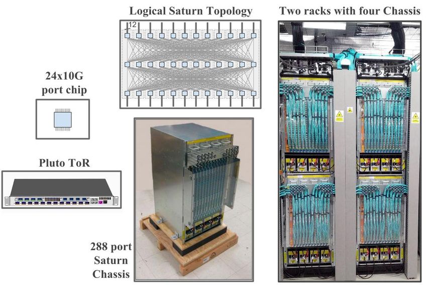
Figure 3: Mix of jobs in an example cluster with 12 blocks
of servers (left). Fraction of traffic in each block destined         Figure 4: A generic 3 tier Clos architecture with edge
for remote blocks (right).                                            switches (ToRs), aggregation blocks and spine blocks. All
                                                                      generations of Clos fabrics deployed in our datacenters fol-
                                                                      low variants of this architecture.

width applications had to fit under a single ToR to
                                                                      pain points. Increasing bandwidth per server would
avoid the heavily oversubscribed ToR uplinks. Deploy-
                                                                      have substantially increased cost per server and reduced
ing large clusters was important to our services because
                                                                      cluster scale.
there were many affiliated applications that benefited
                                                                         We realized that existing commercial solutions could
from high bandwidth communication. Consider large-
                                                                      not meet our scale, management, and cost requirements.
scale data processing to produce and continuously re-
                                                                      Hence, we decided to build our own custom data center
fresh a search index, web search, and serving ads as
                                                                      network hardware and software. We started with the
affiliated applications. Larger clusters also substan-
                                                                      key insight that we could scale cluster fabrics to near
tially improve bin-packing efficiency for job scheduling
                                                                      arbitrary size by leveraging Clos topologies (Figure 4)
by reducing stranding from cases where a job cannot
                                                                      and the then-emerging (ca. 2003) merchant switching
be scheduled in any one cluster despite the aggregate
                                                                      silicon industry [12]. Table 1 summarizes a number of
availability of sufficient resources across multiple small
                                                                      the top-level challenges we faced in constructing and
clusters.
                                                                      managing building-scale network fabrics. The following
   Maximum cluster scale is important for a more sub-
                                                                      sections explain these challenges and the rationale for
tle reason. Power is distributed hierarchically at the
                                                                      our approach in detail.
granularity of the building, multi-Megawatt power gen-
                                                                         For brevity, we omit detailed discussion of related
erators, and physical datacenter rows. Each level of hi-
                                                                      work in this paper. However, our topological approach,
erarchy represents a unit of failure and maintenance.
                                                                      reliance on merchant silicon, and load balancing across
For availability, cluster scheduling purposely spreads
                                                                      multipath are substantially similar to contemporaneous
jobs across multiple rows. Similarly, the required re-
                                                                      research [2,15]. In addition to outlining the evolution of
dundancy in storage systems is in part determined by
                                                                      our network, we further describe inter cluster network-
the fraction of a cluster that may simultaneously fail as
                                                                      ing, network management issues, and detail our control
a result of a power event. Hence, larger clusters lead to
                                                                      protocols. Our centralized control protocols running on
lower storage overhead and more efficient job scheduling
                                                                      switch embedded processors are also related to subse-
while meeting diversity requirements.
                                                                      quent substantial efforts in Software Defined Network-
   Running storage across a cluster requires both rack
                                                                      ing (SDN) [13]. Based on our experience in the dat-
and power diversity to avoid correlated failures. Hence,
                                                                      acenter, we later applied SDN to our Wide Area Net-
cluster data should be spread across the cluster’s failure
                                                                      work [19]. For the WAN, more CPU intensive traffic
domains for resilience. However, such spreading natu-
                                                                      engineering and BGP routing protocols led us to move
rally eliminates locality and drives the need for uni-
                                                                      control protocols onto external servers with more plen-
form bandwidth across the cluster. Consequently, stor-
                                                                      tiful CPU from the embedded CPU controllers we were
age placement and job scheduling have little locality in
                                                                      able to utilize for our initial datacenter deployments.
our cluster traffic, as shown in Figure 3. For a rep-
                                                                         Recent work on alternate network topologies such as
resentative cluster with 12 blocks (groups of racks) of
                                                                      HyperX [1], Dcell [17], BCube [16] and Jellyfish [22]
servers, we show the fraction of traffic destined for re-
                                                                      deliver more efficient bandwidth for uniform random
mote blocks. If traffic were spread uniformly across the
                                                                      communication patterns. However, to date, we have
cluster, we would expect 11/12 of the traffic (92%) to
                                                                      found that the benefits of these topologies do not make
be destined for other blocks. Figure 3 shows approxi-
                                                                      up for the cabling, management, and routing challenges
mately this distribution for the median block, with only
                                                                      and complexity.
moderate deviation.
   While our traditional cluster network architecture
largely met our scale needs, it fell short in terms of                3.     NETWORK EVOLUTION
overall performance and cost. Bandwidth per host was
severely limited to an average of 100Mbps. Packet drops               3.1      Firehose 1.0
associated with incast [8] and outcast [21] were severe                    Table 2 summarizes the multiple generations of our

                                                                185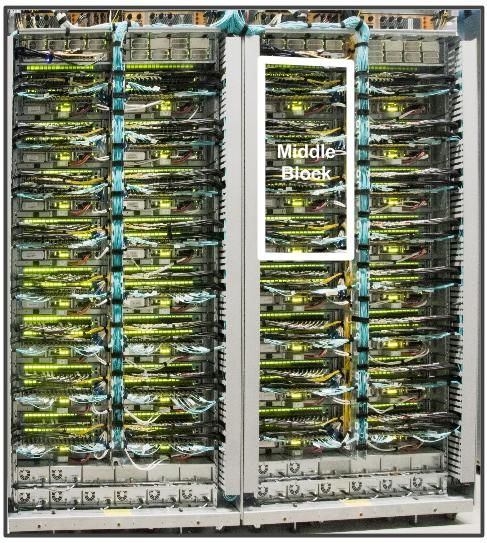
Challenge                                    Our Approach (Section Discussed in)
  Introducing the network to production        Initially deploy as bag-on-the-side with a fail-safe big-red button (3.2)
  High availability from cheaper components    Redundancy in fabric, diversity in deployment, robust software, necessary
                                               protocols only, reliable out of band control plane (3.2, 3.3, 5.1)
  High fiber count for deployment              Cable bundling to optimize and expedite deployment (3.3)
  Individual racks can leverage full uplink    Introduce Cluster Border Routers to aggregate external bandwidth shared
  capacity to external clusters                by all server racks (4.1)
  Incremental deployment                       Depopulate switches and optics (3.3)
  Routing scalability                          Scalable in-house IGP, centralized topology view and route control (5.2)
  Interoperate with external vendor gear       Use standard BGP between Cluster Border Routers and vendor gear (5.2.5)
  Small on-chip buffers                        Congestion window bounding on servers, ECN, dynamic buffer sharing of
                                               chip buffers, QoS (6.1)
  Routing with massive multipath               Granular control over ECMP tables with proprietary IGP (5.1)
  Operating at scale                           Leverage existing server installation, monitoring software; tools build and
                                               operate fabric as a whole; move beyond individual chassis-centric network
                                               view; single cluster-wide configuration (5.3)
  Inter cluster networking                     Portable software, modular hardware in other applications in the network
                                               hierarchy (4.2)

                 Table 1: High-level summary of challenges we faced and our approach to address them.

 Datacenter      First       Merchant         ToR          Aggregation       Spine Block     Fabric   Host      Bisection
 Generation      Deployed    Silicon          Config       Block Config      Config          Speed    Speed     BW
 Four-Post CRs   2004        vendor           48x1G        -                 -               10G      1G        2T
 Firehose 1.0    2005        8x10G            2x10G up     2x32x10G (B)      32x10G (NB)     10G      1G        10T
                             4x10G (ToR)      24x1G down
 Firehose 1.1    2006        8x10G            4x10G up     64x10G (B)        32x10G (NB)     10G      1G        10T
                                              48x1G down
 Watchtower      2008        16x10G           4x10G up     4x128x10G (NB) 128x10G (NB) 10G            nx1G      82T
                                              48x1G down
 Saturn          2009        24x10G           24x10G       4x288x10G (NB) 288x10G (NB) 10G   nx10G 207T
 Jupiter         2012        16x40G           16x40G       8x128x40G (B) 128x40G (NB) 10/40G nx10G/ 1.3P
                                                                                             nx40G

       Table 2: Multiple generations of datacenter networks. (B) indicates blocking, (NB) indicates Nonblocking.

cluster network. With our initial approach, Firehose 1.0
(or FH1.0), our nominal goal was to deliver 1Gbps of
nonblocking bisection bandwidth to each of 10K servers.
Figure 5 details the FH1.0 topology. Our starting point
was 8x10G switches for the fabric and 4x10G switches
for ToRs. The fabric switch was deployed with 4x10G
ports facing up and 4x10G facing down in all stages but
the topmost stage, which had all 8x10G ports facing
down. The ToR switch delivered 2x10GE ports to the
fabric and 24x1GE south-facing ports of which 20x1GE
were connected to servers. Each aggregation block
hosted 16 ToRs (320 machines) and exposed 32x10G
ports towards 32 spine blocks. Each spine block had
32x10G towards 32 aggregation blocks resulting in a
                                                                  Figure 5: Firehose 1.0 topology. Top right shows a sam-
fabric that scaled to 10K machines at 1G average band-            ple 8x10G port fabric board in Firehose 1.0, which formed
width to any machine in the fabric.                               Stages 2, 3 or 4 of the topology.
   A key drawback of the topology was the low radix of
the ToR switch, which caused issues when links failed.
If the left uplink of a source ToR and the right uplink
of a destination ToR failed within a MTTR window,                   Since we did not have any experience building
machines on these ToRs could not communicate with                 switches but we did have experience building servers,
each other even though they could communicate with                we attempted to integrate the switching fabric into the
other machines - an intransitive disconnect not handled           servers via a PCI board. See top right inset in Fig-
well by applications.                                             ure 5. However, the uptime of servers was less than
                                                                  ideal. Servers crashed and were upgraded more fre-

                                                            186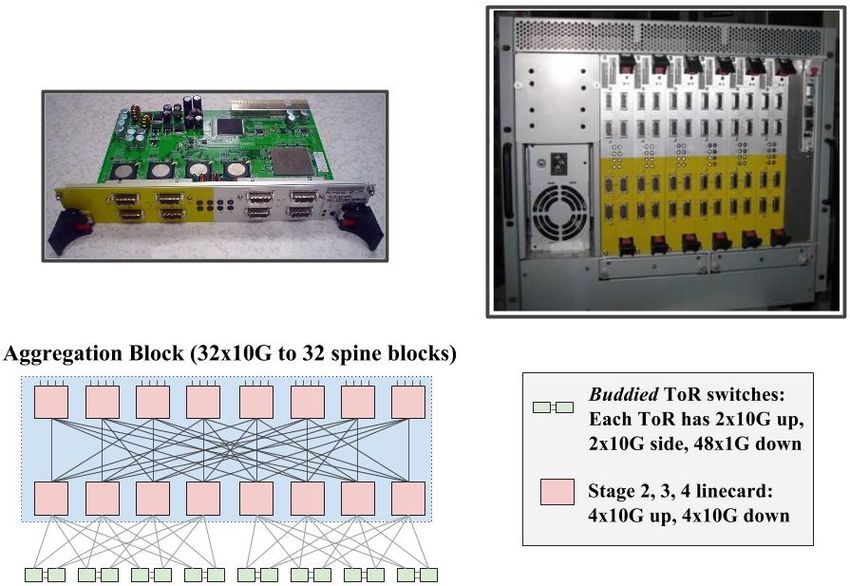
Figure 6: Firehose 1.1 packaging and topology. The top left           Figure 7: Two Firehose racks (left), each with 3 chassis
picture shows a linecard version of the board from Figure 5.          with bulky CX4 cables from remote racks. The top right
The top right picture shows a Firehose 1.1 chassis housing            figure shows an aisle of cabled racks.
6 such linecards. The bottom figure shows the aggregation
block in Firehose 1.1, which was different from Firehose 1.0.

                                                                      at most 2:1 oversubscription, we decided to buddy two
quently than desired with long reboot times. Network                  ToR switches together. Of the 4x10G uplinks in each
disruptions from server failure were especially problem-              ToR, two were connected to the fabric while two were
atic for servers housing ToRs connecting multiple other               connected sideways to the paired ToR. Traffic from ma-
servers to the first stage of the topology.                           chines under a ToR could use all four uplinks to burst to
   The resulting wiring complexity for server to server               the fabric, though bandwidth under contention would
connectivity, electrical reliability issues, availability and         be lower. The stage 2 and 3 switches within an ag-
general issues associated with our first foray into switch-           gregation block were cabled in a single block (vs. 2
ing doomed the effort to never seeing production traffic.             disjoint blocks in FH1.0) in a configuration similar to
At the same time, we consider FH1.0 to be a landmark                  a Flat Neighborhood Network [11]. With up to 40 ma-
effort internally. Without it and the associated learning,            chines under each ToR, the FH1.1 aggregation block
the efforts that followed would not have been possible.               could scale to 640 machines at 2:1 oversubscription. The
                                                                      changes in the aggregation block allowed Firehose 1.1
3.2    Firehose 1.1: First Production Clos                            to scale to 2x the number of machines while being much
   Our first production deployment of a custom data-                  more robust to link failures compared to FH1.0.
center cluster fabric was called Firehose 1.1 (or FH1.1),                The copper interconnect for FH1.1 was a significant
a variation of the FH1.0 architecture. We had learned                 challenge. Figure 7 shows the chassis in production
from FH1.0 to not use regular servers to house switch                 deployment. Building, testing, and deploying the net-
chips. Thus, we built custom enclosures that standard-                work was labor intensive and error prone. The 14m
ized around the Compact PCI chassis each with 6 inde-                 length restrictions of our CX4 cables required careful
pendent linecards and a dedicated Single-Board Com-                   placement of each component of the multistage topol-
puter (SBC) to control the linecards using PCI. See in-               ogy. The longest distances were typically between our
sets in Figure 6. The fabric chassis did not contain any              ToRs and the next stage of the Firehose switching in-
backplane to interconnect the switch chips. All ports                 frastructure. To improve deployability, we worked on a
connected to external copper cables that were wired on                solution to run fiber only for this stage of the network
the datacenter floor. The linecards were a different form             topology. We collaborated with vendors to develop cus-
factor of the same boards used in FH1.0 for stages 2-5.               tom Electrical/Optical/Electrical (EOE) cables for this
We built a separate out-of-band Control Plane Network                 interconnect. The orange cable in the bottom right of
(CPN) to configure and manage the SBCs of the fabric.                 Figure 7 is an EOE cable capable of spanning 100m
   The FH1.1 topology was a variant of the one used in                compared to the bulkier 14m CX4 cable to its right.
FH1.0. While the spine block was identical to FH1.0,                     A major concern with FH1.1 in production was de-
the edge aggregation block illustrated in Figure 6 had                ploying an unproven new network technology for our
a few differences. We used two 4x10G+24x1G switch                     mission critical applications. To mitigate risk, we de-
chips side connected on the board with 2x10G links for                ployed Firehose 1.1 in conjunction with our legacy four-
ToRs. The resulting configuration was a ToR switch                    post cluster fabrics as shown in Figure 8. We main-
with 4x10G uplinks and 48x1G links to servers. ToRs                   tained a simple configuration; the ToR would forward
were developed as separate 1RU switches each with its                 default traffic to the four-post cluster (e.g., for connec-
own CPU controller. To scale to 20k machines with                     tivity to external clusters/data centers) while more spe-

                                                                187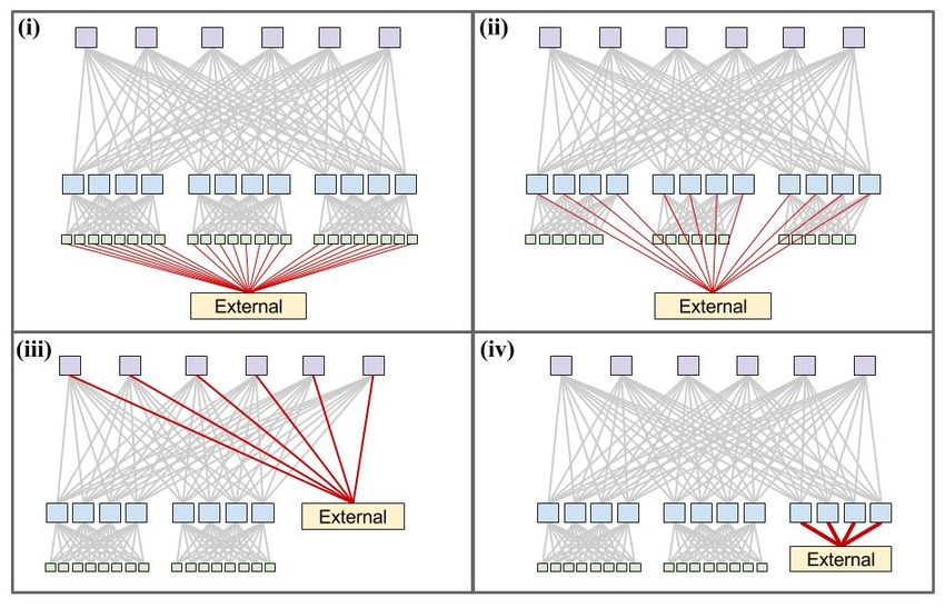
Figure 8: Firehose 1.1 deployed as a bag-on-the-side Clos
fabric.

                                                                    Figure 10: Reducing deployment complexity by bundling
                                                                    cables. Stages 1, 2 and 3 in the fabric are labeled S1, S2 and
                                                                    S3, respectively.

                                                                       # Individual cables                              15872
                                                                       # S2-S3 bundles (16-way)                         512
                                                                       Normalized cost of fiber/m in 16-way bundle      55%
                                                                       # S2-ToR bundles (8-way)                         960
                                                                       Normalized cost of fiber/m in 8-way bundle       60%
                                                                       # Total cable bundles                            1472
                                                                       Normalized cost of fiber/m with bundling         57%
                                                                       (capex + opex)

                                                                       Table 3: Benefits of cable bundling in Watchtower.

                                                                    chassis along with its internal topology and cabling.
                                                                    Watchtower consists of eight line cards, each with three
                                                                    switch chips. Two chips on each linecard have half their
Figure 9: A 128x10G port Watchtower chassis (top left).             ports externally facing, for a total of 16x10GE SFP+
The internal non-blocking topology over eight linecards             ports. All three chips also connect to a backplane for
(bottom left). Four chassis housed in two racks cabled with         port to port connectivity. Watchtower deployment, as
fiber (right).                                                      seen in Figure 9 was substantially easier than the earlier
                                                                    Firehose deployments. The larger bandwidth density
                                                                    of the switching silicon also allowed us to build larger
cific intra-cluster traffic would use the uplinks to Fire-          fabrics with more bandwidth to individual servers, a
hose 1.1. Since our four-post cluster employed 1G links,            necessity as servers were employing an ever-increasing
we only needed to reserve four 1GE ToR ports. We built              number of cores.
a Big Red Button fail-safe to configure the ToRs to avoid              Fiber bundling further reduced the cabling complex-
Firehose uplinks in case of catastrophic failure.                   ity of Watchtower clusters. Figure 10 shows a Watch-
                                                                    tower fabric deployment without any cable bundling.
3.3       Watchtower: Global Deployment                             Individual fibers of varying length need to be pulled
   Our deployment experience with Firehose 1.1 was                  from each chassis location, leading to significant deploy-
largely positive. We showed that services could en-                 ment overhead. The bottom figure shows how bundling
joy substantially more bandwidth than with traditional              can substantially reduce complexity. We deploy two
architectures, all with lower cost per unit bandwidth.              chassis in each rack and co-locate two racks. We can
Firehose 1.1 went into production with a handful of clus-           then pull cable bundles to the midpoint of the co-located
ters and remained operational until recently. The main              racks, where each bundle is split to each rack and then
drawback to Firehose 1.1 was the deployment challenges              further to each chassis.
with the external copper cabling.                                      Finally, manufacturing fiber in bundles is more cost
   We used these experiences to design Watchtower, our              effective than individual strands.       Cable bundling
third-generation cluster fabric. The key idea was to                helped reduce fiber cost (capex + opex) by nearly 40%
leverage the next-generation merchant silicon switch                and expedited bringup of Watchtower fabric by multi-
chips, 16x10G, to build a traditional switch chassis with           ple weeks. Table 3 summarizes the bundling and cost
a backplane. Figure 9 shows the half rack Watchtower                savings.

                                                              188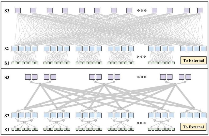
Figure 11: Two ways to depopulate the fabric for 50% ca-
pacity.

   Figure 10 also depicts how we started connecting our
cluster fabric to the external inter cluster networking.
We defer detailed discussion to Section 4.                        Figure 12: Components of a Saturn fabric. A 24x10G Pluto
   While Watchtower cluster fabrics were substantially            ToR Switch and a 12-linecard 288x10G Saturn chassis (in-
                                                                  cluding logical topology) built from the same switch chip.
cheaper and of greater scale than anything available for          Four Saturn chassis housed in two racks cabled with fiber
purchase, the absolute cost remained substantial. We              (right).
used two observations to drive additional cost optimiza-
tions. First, there is natural variation in the bandwidth
demands of individual clusters. Second, the dominant              Saturn chassis supports 12-linecards to provide a 288
cost of our fabrics was in the optics and the associated          port non-blocking switch. These chassis are coupled
fiber.                                                            with new Pluto single-chip ToR switches; see Figure 12.
   Hence, we enabled Watchtower fabrics to support de-            In the default configuration, Pluto supports 20 servers
populated deployment, where we initially deployed only            with 4x10G provisioned to the cluster fabric for an av-
50% of the maximum bisection bandwidth. Impor-                    erage bandwidth of 2 Gbps for each server. For more
tantly, as the bandwidth demands of a depop cluster               bandwidth-hungry servers, we could configure the Pluto
grew, we could fully populate it to 100% bisection in             ToR with 8x10G uplinks and 16x10G to servers provid-
place. Figure 11 shows two high-level options, (A) and            ing 5 Gbps to each server. Importantly, servers could
(B), to depopulate switches, optics, and fiber, shown in          burst at 10Gbps across the fabric for the first time.
red. (A) achieves 50% capacity by depopulating half
of the S2 switches and all fiber and optics touching any          3.5    Jupiter: A 40G Datacenter-scale Fab-
depopulated S2 switch. (B) instead depopulates half S3                   ric
switches and associated fiber and optics. (A) shows 2x               As bandwidth requirements per server continued to
more depopulated elements vs. (B) for the same fabric             grow, so did the need for uniform bandwidth across all
capacity.                                                         clusters in the datacenter. With the advent of dense
   (A) requires all spine S3 chassis to be deployed up            40G capable merchant silicon, we could consider ex-
front even though edge aggregation blocks may be de-              panding our Clos fabric across the entire datacenter sub-
ployed slowly leading to higher initial cost. (B) has a           suming the inter-cluster networking layer. This would
more gradual upfront cost as all spine chassis are not            potentially enable an unprecedented pool of compute
deployed initially. Another advantage of (B) over (A)             and storage for application scheduling. Critically, the
is that each ToR has twice the burst bandwidth.                   unit of maintenance could be kept small enough relative
   In Watchtower and Saturn (Section 3.4) fabrics, we             to the size of the fabric that most applications could
chose option (A) because it maximized cost savings. For           now be agnostic to network maintenance windows un-
Jupiter fabrics (Section 3.5), we moved to option (B)             like previous generations of the network.
because the upfront cost of deploying the entire spine               Jupiter, our next generation datacenter fabric,
increased as we moved toward building-size fabrics and            needed to scale more than 6x the size of our largest
the benefits of higher ToR bandwidth became more ev-              existing fabric. Unlike previous iterations, we set a re-
ident.                                                            quirement for incremental deployment of new network
                                                                  technology because the cost in resource stranding and
3.4       Saturn:    Fabric Scaling and 10G                       downtime was too high. Upgrading networks by sim-
          Servers                                                 ply forklifting existing clusters stranded hosts already
   Saturn was the next iteration of our cluster archi-            in production. With Jupiter, new technology would
tecture. The principal goals were to respond to con-              need to be introduced into the network in situ. Hence,
tinued increases in server bandwidth demands and to               the fabric must support heterogeneous hardware and
further increase maximum cluster scale. Saturn was                speeds. Because of the sheer scale, events in the net-
built from 24x10G merchant silicon building blocks. A             work (both planned and unplanned) were expected to

                                                            189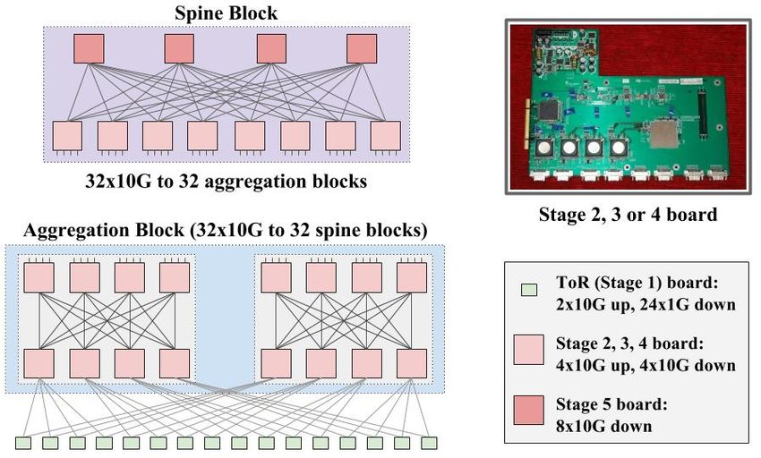
Figure 13: Building blocks used in the Jupiter topology.

be more frequent, requiring Jupiter to react robustly                    Figure 14: Jupiter Middle blocks housed in racks.
and gracefully to such events.
   At Jupiter scale, we had to design the fabric through
                                                                     We deploy four MBs in a single networking rack as de-
individual building blocks. However, the size of the
                                                                   picted in Figure 14. Similarly, a spine networking rack
building block was a key point of discussion. At one
                                                                   houses two pre-wired spine blocks. Cabling on the dat-
extreme was the Firehose approach, where each switch
                                                                   acenter floor involves connecting fiber cable bundles be-
chip was cabled to others on the datacenter floor. On
                                                                   tween these networking racks and also to ToR switches
the other extreme, we could go the way of Watchtower
                                                                   atop server racks. In its largest configuration, Jupiter
and Saturn fabrics - i.e., build the largest non-blocking,
                                                                   supports 1.3 Pbps bisection bandwidth among servers.
two-stage chassis possible with the current merchant sil-
icon, employing the chassis in various roles within the
fabric.                                                            4.     EXTERNAL CONNECTIVITY
   For the first generation of Jupiter (Figure 13), we
chose a middle path regarding building block size. Our             4.1     WCC: Decommissioning                     Cluster
unit of deployment was a Centauri chassis, a 4RU                           Routers
chassis housing two linecards, each with two switch                   In this section, we describe how we employed existing
chips with 16x40G ports controlled by a separate CPU               cluster networking building blocks to improve the per-
linecard. Each port could be configured in 4x10G or                formance and robustness of our inter cluster networking
40G mode. There were no backplane data connections                 fabrics. Chronologically, this work took place between
between these chips; all ports were accessible on the              Watchtower and Saturn.
front panel of the chassis.                                           Through the first few Watchtower deployments, all
   We employed the Centauri switch as a ToR switch                 cluster fabrics were deployed as bag-on-the-side net-
with each of the 4 chips serving a subnet of machines.             works coexisting with legacy networks (Figure 8). Time
In one ToR configuration, we configured each chip with             and experience ameliorated safety concerns, tipping the
48x10G to servers and 16x10G to the fabric. Servers                balance in favor of reducing the operational complexity,
could be configured with 40G burst bandwidth for the               cost, and performance limitations of deploying two par-
first time in production (see Table 2). Four Centauris             allel networks. Limiting ToR burst bandwidth out of
made up a Middle Block (MB) for use in the aggregation             the cluster was particularly restrictive when migrating
block. The logical topology of an MB was a 2-stage                 services or copying large search indexes across clusters.
blocking network, with 256x10G links available for ToR                Hence, our next goal was to decommission the Clus-
connectivity and 64x40G available for connectivity to              ter Routers (CRs) by connecting the fabric directly to
the rest of the fabric through the spine.                          the inter-cluster networking layer with Cluster Border
   Each ToR chip connects to eight such MBs with dual              Routers (CBRs). This effort was internally called WCC.
redundant 10G links. The dual redundancy aids fast re-             Figure 15 shows various choices for external connectiv-
convergence for the common case of single link failure or          ity: i) reserve some links from each ToR, ii) reserve
maintenance. Each aggregation block exposes 512x40G                ports in each aggregation block, iii) reserve ports in each
(full pop) or 256x40G (depop) links towards the spine              spine block, iv) build a separate aggregation block for
blocks. Jupiter employs six Centauris in a spine block             external connectivity. Note that i) was similar to our
exposing 128x40G ports towards the aggregation blocks.             approach in Firehose 1.1. Further, both options i) and
We limited the size of Jupiter to 64 aggregation blocks            ii) could not improve external burst bandwidth assum-
for dual redundant links between each spine block and              ing shortest path routing.
aggregation block pair at the largest scale, once again               However, options iii) and iv) provide the entire pool
for local reconvergence on single link failure.                    of external bandwidth to each aggregation block. We

                                                             190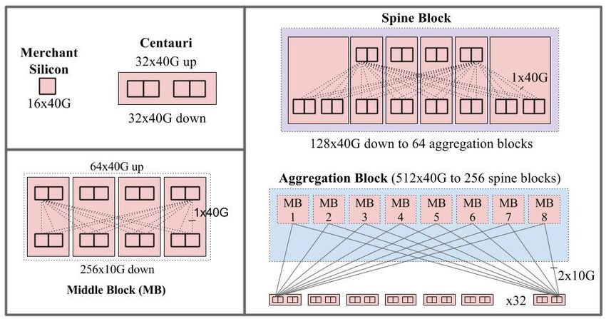
Figure 16: Two-stage fabrics used for inter-cluster and
Figure 15: Four options to connect to the external network           intra-campus connectivity.
layer.

                                                                     and 5.76Tbps in Saturn fabrics. However, our exter-
chose option iv) because we wanted an isolated layer                 nal networking layers were still based on expensive and
of switches to peer with external routers rather than                port-constrained vendor gear. The third step in the evo-
spreading peering functionality across the entire set of             lution of our network fabrics involved replacing vendor-
spine switches. We deemed this approach safer because                based inter cluster switching. Our approach, Freedome,
we wanted to limit the blast radius from an external                 targets massive inter-cluster bandwidth within build-
facing configuration change and because it limited the               ings and the campus at lower cost than existing solu-
places where we would have to integrate our in-house                 tions.
IGP (Section 5.2) with external routing protocols.                      We employed the BGP capability we developed in our
   As a rule of thumb, we allocated 10% of aggregate                 cluster routers (Section 5.2.5) to build two-stage fabrics
intra-cluster bandwidth for external connectivity us-                that could speak BGP at both the inter cluster and
ing one to three aggregation blocks. These aggrega-                  intra campus connectivity layers. See Figure 16. We
tion blocks were physically and topologically identical              configure a collection of routers in blocks called Free-
to those used for ToR connectivity. However, we reallo-              dome Blocks as shown in the top figure. Each block ex-
cated the ports normally employed for ToR connectivity               poses 8x more south-facing ports (cluster facing) than
to connect to external fabrics.                                      north-facing ports (next-level in the hierarchy). Each
   We configured parallel links between each CBR                     block has two types of switch roles; the Freedome Edge
switch in these blocks and an external switch as Link                Routers delivered south-facing ports while the Free-
Aggregation Groups (LAGs) or trunks. We used                         dome Border Routers delivered the north-facing ports.
standard external BGP (eBGP) routing between the                     The Freedome Block employs eBGP to connect to both
CBRs and the inter-cluster networking switches. CBR                  north and south facing peers. We use iBGP internal to
switches learned the default route via BGP from the                  each block with the Border Routers configured as route
external peers and redistributed the route through                   reflectors [6].
Firepath, our intra-cluster IGP protocol (Section 5.2).                 A Datacenter Freedome typically comprises 4 inde-
   WCC enabled the cluster fabric to be truly stan-                  pendent blocks to connect multiple clusters in the same
dalone and unlocked high throughput bulk data transfer               datacenter building. Inter-cluster traffic local to the
between clusters. Moreover, the modular hardware and                 same building would travel from the source cluster’s
software of the CBR switch would find application in                 CBR layer to the Datacenter Freedome, typically stay-
diverse use cases in our networking hierarchy.                       ing local to the Edge Router layer, and finally to the
                                                                     CBR layer of the destination cluster. We connect the
4.2      Inter-Cluster Networking                                    Freedome Border Router ports to the campus connec-
   We deploy multiple clusters within the same build-                tivity layer to the north. The bottom left figure in Fig-
ing and multiple buildings on the same campus. Given                 ure 16 depicts a Datacenter Freedome. We provision 8x
the relationship between physical distance and network               more bandwidth for traffic within a building than for
cost, our job scheduling and resource allocation infras-             traffic between buildings in the same campus.
tructure leverages campus-level and building-level local-               Recursively, a Campus Freedome also typically com-
ity to co-locate loosely affiliated services as close to one         prises 4 independent Freedome Blocks to connect mul-
another as possible. The CBRs developed for WCC en-                  tiple Datacenter Freedomes in a campus on the south
abled clusters to connect to inter cluster networks with             and the WAN connectivity layer on the north-facing
massive bandwidth. Each aggregation block supported                  side. The bottom right figure in Figure 16 depicts a
2.56Tbps of external connectivity in Watchtower fabrics              Campus Freedome.

                                                               191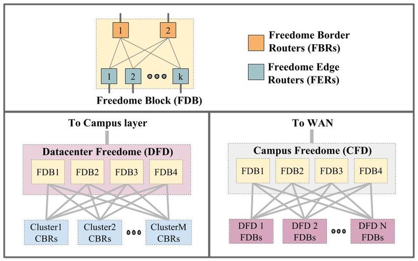
Deploying independent blocks is crucial for maintain-           Google’s B4 WAN [19]. Details of Jupiter’s control ar-
ing performance on Freedomes since each block can be              chitecture are beyond the scope of this paper.
independently removed from service, or drained, and up-
graded with an aggregate capacity degradation of 25%.             5.2     Routing
Once we had rolled out the Freedomes for campus net-                 We now present the key components of Firepath, our
working, the BGP router would also find application in            routing architecture for Firehose, Watchtower, and Sat-
our WAN deployment [19].                                          urn fabrics. A number of these components anticipate
                                                                  some of the principles of modern Software Defined Net-
                                                                  working, especially in using logically centralized state
5.    SOFTWARE CONTROL                                            and control. First, all switches are configured with the
                                                                  baseline or intended topology. The switches learn actual
5.1   Discussion                                                  configuration and link state through pair-wise neighbor
   As we set out to build the control plane for our net-          discovery. Next, routing proceeds with each switch ex-
work hardware, we faced the following high level trade-           changing its local view of connectivity with a centralized
off: deploy traditional decentralized routing protocols           Firepath master, which redistributes global link state to
such as OSPF/IS-IS/BGP to manage our fabrics or                   all switches. Switches locally calculate forwarding ta-
build a custom control plane to leverage some of the              bles based on this current view of network topology. To
unique characteristics and homogeneity of our cluster             maintain robustness, we implement a Firepath master
network. Traditional routing protocols had the advan-             election protocol. Finally, we leverage standard BGP
tage of being proven and robust.                                  only for route exchange at the edge of our fabric, redis-
   We chose to build our own control plane for a number           tributing BGP-learned routes through Firepath.
of reasons. First, and most important, existing routing
protocols did not at the time have good support for               5.2.1    Neighbor Discovery to Verify Connectivity
multipath, equal-cost forwarding. Second, there were                 Building a fabric with thousands of cables invariably
no high quality open source routing stacks a decade ago.          leads to multiple cabling errors. Moreover, correctly ca-
Further, it was a substantial amount of work to mod-              bled links may be re-connected incorrectly after mainte-
ify our hardware switch stack to tunnel control-protocol          nance such as linecard replacement. Allowing traffic to
packets running inline between hardware line cards to             use a miscabled link can lead to forwarding loops. Links
protocol processes. Third, we were concerned about the            that fail unidirectionally or develop high packet error
protocol overhead of running broadcast-based routing              rates should also be avoided and scheduled for replace-
protocols across fabrics of the scale we were targeting           ment. To address these issues, we developed Neighbor
with hundreds or even thousands of switching elements.            Discovery (ND), an online liveness and peer correctness
Scaling techniques like OSPF Areas [20] appeared hard             checking protocol.
to configure and to reason about [23]. Fourth, network               Neighbor Discovery (ND) uses the configured view
manageability was a key concern and maintaining hun-              of cluster topology together with a switch’s local ID
dreds of independent switch stacks and, e.g., BGP con-            to determine the expected peer IDs of its local ports.
figurations seemed daunting.                                      It regularly exchanges its local port ID, expected peer
   Our approach was driven by the need to route across            port ID, discovered peer port ID, and link error signal.
a largely static topology with massive multipath. Each            Doing so allows ND on both ends of a link to verify
switch had a predefined role according to its location in         correct cabling.
the fabric and could be configured as such. A central-               The Interface Manager (IFM) module on each
ized solution where a route controller collected dynamic          switch’s embedded stack continuously monitors the ND
link state information and redistributed this link state          state of each port, declaring a port up to the routing
to all switches over a reliable out-of-band Control Plane         process only if it is both PHY UP and ND UP. Linecard
Network (CPN) appeared to be substantially simpler                LEDs display the ND status of each port to assist phys-
and more efficient from a computation and communi-                ical debugging in the field. Our monitoring infrastruc-
cation perspective. The switches could then calculate             ture also collects and displays all link status on various
forwarding tables based on current link state as deltas           dashboards. ND also serves as a keepalive protocol to
relative to the underlying, known static topology that            ensure peers are alive and functional. If the remote
was pushed to all switches.                                       software has crashed or shut down, peer ND instances
   Overall, we treated the datacenter network as a sin-           will eventually report the failure to the interface man-
gle fabric with tens of thousands of ports rather than            ager, which in turn will declare the interface down to
a collection of hundreds of autonomous switches that              the routing process.
had to dynamically discover information about the fab-
ric. We were, at this time, inspired by the success of            5.2.2    Firepath
large-scale distributed storage systems with a central-             We support Layer 3 routing all the way to the
ized manager [14]. Our design informed the control                ToRs via a custom Interior Gateway Protocol (IGP),
architecture for both Jupiter datacenter networks and             Firepath. Each ToR implements a Layer 2 subnet, i.e.,

                                                            192
Failure Recovery Convergence type
Event time (ms)
S2-S3 link 125 Local; affected S2, S3 chas-
sis route around failed link
S3 chassis 325 Local; adjacent S2s route
around failed S3
ToR-S2 link 4000 Non-local; all S3s avoid one
S2 for impacted ToR
S2 chassis 325 Local; adjacent S3s, ToRs
route around failed S2
Table 4: Summary of convergence times in a Saturn cluster.
Figure 17: Firepath component interactions.
clients, the master throttles the number of LSD changes
it sends to clients.
The master also maintains a keepalive protocol with
the clients. It sends periodic heartbeat messages with
its master ID and the current LSD version number. If
a client loses synchronization with the master, e.g., by
missing an LSD message, it requests a full LSD update.
5.2.3 Path Diversity and Convergence on Fail-
ures
For rapid convergence on interface state change, each
client computes the new routing solution and updates
the forwarding tables independently upon receiving an
Figure 18: Protocol messages between Firepath client and LSD update. Since clients do not coordinate during
Firepath master, between Firepath masters and between
CBR and external BGP speakers. convergence, the network can experience small transient
loss while the network transitions from the old to the
new state. However, assuming churn is transient, all
all machines under one ToR are part of a broadcast do- switches eventually act on a globally consistent view of
main. The L3 subnets assigned to ToRs are aligned to network state.
aid aggregation in limited forwarding tables in merchant Table 4 shows the reaction time to route around com-
silicon. ponent failures. Due to high path diversity, most fail-
Firepath implements centralized topology state dis- ures require only local convergence, i.e., elements adja-
tribution, but distributed forwarding table computation cent to the failure typically have multiple other viable
with two main components. A Firepath client runs on next hops to the eventual destination. The switch’s
each fabric switch, and a set of redundant Firepath mas- embedded stack can quickly prune the failed link/next
ters run on a selected subset of spine switches. Clients hop from an ECMP group containing the impacted link.
communicate with the elected master over the Control The ToR-S2 link failure requires non-local convergence
Plane Network (CPN). Figure 17 shows the interaction and hence takes longer. In this case, all S3 chassis must
between the Firepath client and the rest of the switch avoid one particular S2 chassis for the IP prefix of the
stack. Figure 18 illustrates the protocol message ex- impacted ToR switch. Even this case can be optimized
change between various routing components. if ToRs have multiple links to an S2 switch.
At startup, each client is loaded with the static topol- Firepath LSD updates contain routing changes due to
ogy of the entire fabric called the cluster config. Each planned and unplanned network events. The frequency
client collects the state of its local interfaces from the of such events in a typical cluster (from Figure 3) is
embedded stack’s interface manager and transmits this approximately 2,000 times/month, 70 times/day, or 3
state to the master. The master constructs a Link State times/hour.
Database (LSD) with a monotonically increasing ver-
sion number and distributes it to all clients via UDP/IP 5.2.4 Firepath Master Redundancy Protocol
multicast over the CPN. After the initial full update, a The centralized Firepath master is a critical compo-
subsequent LSD contains only the diffs from the previ- nent in the Firepath system. It collects and distributes
ous state. The entire network’s LSD fits within a 64KB interface states and synchronizes the Firepath clients
payload. On receiving an LSD update, each client com- via a keepalive protocol. For availability, we run redun-
putes shortest path forwarding with Equal-Cost Multi- dant master instances on pre-selected spine switches.
Path (ECMP) and programs the hardware forwarding Switches know the candidate masters via their static
tables local to its switch. To prevent overwhelming the configuration.
193The Firepath Master Redundancy Protocol (FMRP) primary goal was to manufacture compute clusters and
handles master election and bookkeeping between the network fabrics as fast as possible throughout the entire
active and backup masters. The active master main- fleet. Thus, we favored simplicity and reproducibility
tains a keepalive with the backup masters and ensures over flexibility. We supported only a limited number
that the current LSD is in sync with the backup mas- of fabric parameters, used to generate all the informa-
ters on a CPN FMRP multicast group. On startup, a tion needed by various groups to deploy the network,
master enters an Init state where it invalidates its LSD and built simple tools and processes to operate the net-
and waits to hear from an existing master. If it hears work. As a result, the system was easily adopted by a
a keepalive from an existing master, it enters a backup wide set of technical and non-technical support person-
state. Otherwise, it enters the electing state where it nel responsible for building data centers.
broadcasts an election request to other master candi-
dates. Typically, the winner of the election is the master 5.3.1 Configuration Generation Approach
with the latest LSD version. Alternately, a preemption Our key strategy was to view the entire cluster net-
mode elects the master based strictly on a priority such work top-down as a single static fabric composed of
as highest IP address. Newly elected masters enter a switches with pre-assigned roles, rather than bottom-
master state. up as a collection of switches individually configured
FMRP has been robust in production over multiple and assembled into a fabric. We also limited the num-
years and many clusters. Since master election is sticky, ber of choices at the cluster-level, essentially providing
a misbehaving master candidate does not cause changes a simple menu of fabric sizes and options, based on the
in mastership and churn in the network. In the rare case projected maximum size of a cluster as well as the chas-
of a CPN partition, a multi-master situation may result, sis type available.
which immediately alerts network operators for manual The configuration system is a pipeline that accepts
intervention. a specification of basic cluster-level parameters such as
the size of the spine, base IP prefix of the cluster and the
5.2.5 Cluster Border Router list of ToRs and their rack indexes. It then generates
Our cluster fabrics peer with external networks via a set of output files for various operations groups: i) a
BGP. To this end, we integrated a BGP stack on the simplified bill of materials for supply chain operations;
CBR with Firepath. This integration has two key as- ii) rack layout details, cable bundling and port mapping
pects: i) enabling the BGP stack on the CBRs to com- for datacenter operations; iii) CPN design and switch
municate inband with external BGP speakers, and ii) addressing details (e.g., DNS) for network operations;
supporting route exchange between the BGP stack and iv) updates to network and monitoring databases and
Firepath. Figure 17B shows the interaction between the systems; v) a common fabric configuration file for the
BGP stack, Firepath, and the switch kernel and embed- switches; and vi) summary data to feed graphical views
ded stack. to audit the logical topology and cluster specifications.
For i) we created a Linux network device (netdev) for We distribute a single monolithic cluster configura-
each external trunk interface running eBGP. As shown tion to all switches (chassis and ToRs) in the cluster.
in Figure 18, BGP protocol packets flow across inband Each switch simply extracts its relevant portion. Doing
links; we use the embedded stack’s packet I/O engine so simplifies configuration generation but every switch
to vector these control packets via the netdevs to the has to be updated with the new config each time the
BGP stack running on the embedded stack. cluster configuration changes. Since cluster configura-
For ii) a proxy process on the CBR exchanges routes tions do not change frequently, this additional overhead
between BGP and Firepath. This process exports intra- is not significant and often necessary since Firepath re-
cluster routes from Firepath into the BGP RIB and quires global topology state.
picks up inter-cluster routes from the BGP RIB, re-
distributing them into Firepath. We made a simplify- 5.3.2 Switch Management Approach
ing assumption by summarizing routes to the cluster- We designed a simple management system on the
prefix for external BGP advertisement and the /0 de- switches. We did not require most of the standard net-
fault route to Firepath. In this way, Firepath manages work management protocols. Instead, we focused on
only a single route for all outbound traffic, assuming protocols to integrate with our existing server manage-
all CBRs are viable for traffic leaving the cluster. Con- ment infrastructure. We benefited from not drawing
versely, we assume all CBRs are viable to reach any part arbitrary lines between server and network infrastruc-
of the cluster from an external network. The rich path ture; in fact, we set out to make switches essentially
diversity inherent to Clos fabrics enables both these sim- look like regular machines to the rest of fleet. Examples
plifying assumptions. include the image management and installation, large
scale monitoring, syslog collection, and global alerting.
5.3 Configuration and Management The embedded stack exports a single Common Man-
Next, we describe our approach to cluster network agement Access Layer (CMAL) interface for external
configuration and management prior to Jupiter. Our systems to manage the device. We limit administra-
194Figure 20: Multi-color fabric chassis upgrade.
Figure 19: Alerts in Firehose/Watchtower fabrics over 9 topology. The left figure divides all chassis into four
months in ’08-’09.
sets. When upgrading the red set, links in dashed red
are disabled. However, the figure illustrates that the
tive updates to draining or disabling specific ports. fabric capacity degrades to 56.25% (75%*75%). The
Since there are multiple software components running right figure shows a more graceful but more time con-
on each switch, they must all simultaneously accept a suming upgrade process involving eight sets. Upgrading
new switch configuration. Hence, we employ a stan- one switch at a time would take too long.
dard two-phase verify-commit protocol for components Troubleshooting misbehaving traffic flows in a net-
on the switch orchestrated by CMAL to deploy new work with such high path diversity is daunting for op-
switch configurations. erators. Therefore, we extended debugging utilities such
Management clients retrieve switch status through as traceroute and ICMP to be aware of the fabric topol-
a simple API. Important services include a local CLI ogy. This helped with triangulating switches in the net-
for an operator to read switch status for debugging, a work that were potentially blackholing flows. We proac-
minimal SNMP agent to support legacy SNMP moni- tively detect such anomalies by running probes across
tors, and a specific monitoring agent that exports data servers randomly distributed in the cluster. On probe
to the network and machine monitoring system. This failures, these servers automatically run traceroutes and
last client allows us to reuse all the scalable monitoring, identify suspect failures in the network.
alerting, time-series databases (TSDB) systems built to
manage our server machine fleet, saving a huge amount 6. EXPERIENCE
of work. Figure 19 presents a sample breakdown of the
type of monitoring/alerts observed in our clusters for a 6.1 Fabric Congestion
period of 9 months in 2008-2009. The high incidence Despite the capacity in our fabrics, our networks
of chassis linecard failures was due to memory errors experienced high congestion drops as utilization ap-
on a particular version of merchant silicon and is not proached 25%. We found several factors contributed
reflective of a trend in linecard failure rates. to congestion: i) inherent burstiness of flows led to in-
admissible traffic in short time intervals typically seen
5.3.3 Fabric Operation and Management as incast [8] or outcast [21]; ii) our commodity switches
For fabric operation and management, we continued possessed limited buffering, which was sub optimal for
with the theme of leveraging the existing scalable infras- our server TCP stack; iii) certain parts of the network
tructure built to manage and operate the server fleet. were intentionally kept oversubscribed to save cost, e.g.,
We built additional tools that were aware of the network the uplinks of a ToR; and iv) imperfect flow hashing es-
fabric as a whole, thus hiding complexity in our manage- pecially during failures and in presence of variation in
ment software. As a result, we could focus on develop- flow volume.
ing only a few tools that were truly specific to our large We used several techniques to alleviate the congestion
scale network deployments, including link/switch qual- in our fabrics. First, we configured our switch hardware
ification, fabric expansion/upgrade, and network trou- schedulers to drop packets based on QoS. Thus, on con-
bleshooting at scale. Also important was collaborating gestion we would discard lower priority traffic. Second,
closely with the network operations team at Google to we tuned the hosts to bound their TCP congestion win-
provide training before introducing each major network dow for intra-cluster traffic to not overrun the small
fabric generation, expediting the ramp of each technol- buffers in our switch chips. Third, for our early fabrics,
ogy across the fleet. we employed link-level pause at ToRs to keep servers
Figure 20 summarizes our approach to fabric software from over-running oversubscribed uplinks. Fourth, we
upgrades. Rather than support in-service firmware up- enabled Explicit Congestion Notification (ECN) on our
grade on our switches, we exploit fabric redundancy for switches and optimized the host stack response to ECN
upgrades. We would like the degradation in fabric ca- signals [3]. Fifth, we monitored application bandwidth
pacity not to exceed 25%. The figure shows two ways to requirements in the face of oversubscription ratios and
upgrade the fabric chassis in multiple steps in the Clos could provision bandwidth by deploying Pluto ToRs
195You can also read