KBox B-202-CFL - USER GUIDE - Kontron
←
→
Page content transcription
If your browser does not render page correctly, please read the page content below
USER GUIDE
Abe mit Karlheiz gesporich und ich darf 2020
KBox B-202-CFL
Doc. User Guide, Rev 1.3
Doc. ID: 1065-5686
www.kontron.com // 1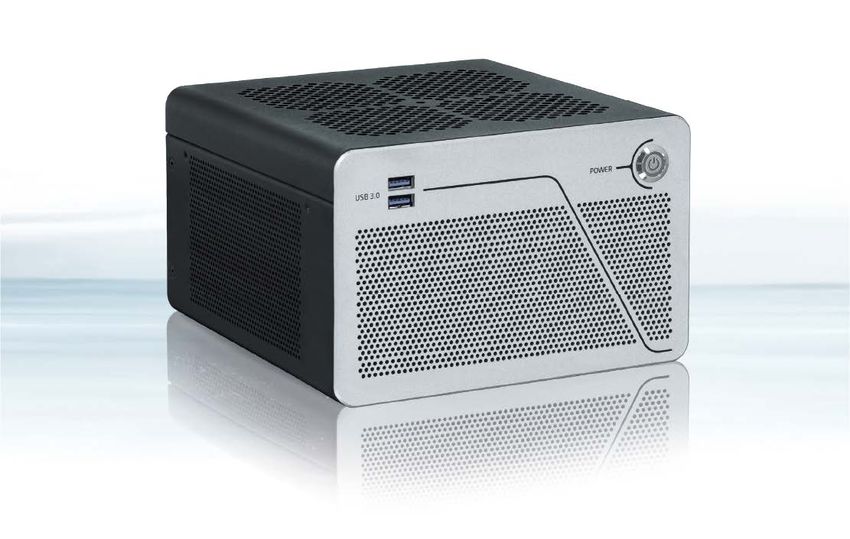
KBox B-202-CFL - User Guide, Rev 1.3

                  This page has been intentionally left blank

www.kontron.com                                                                                 // 2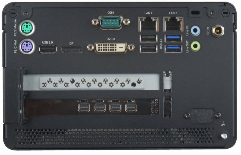
KBox B-202-CFL - User Guide, Rev 1.3 KBOX B-202-CFL - USER GUIDE Disclaimer Kontron would like to point out that the information contained in this user guide may be subject to alteration, particularly as a result of the constant upgrading of Kontron products. This document does not entail any guarantee on the part of Kontron with respect to technical processes described in the user guide or any product characteristics set out in the user guide. Kontron assumes no responsibility or liability for the use of the described product(s), conveys no license or title under any patent, copyright or mask work rights to these products and makes no representations or warranties that these products are free from patent, copyright or mask work right infringement unless otherwise specified. Applications that are described in this user guide are for illustration purposes only. Kontron makes no representation or warranty that such application will be suitable for the specified use without further testing or modification. Kontron expressly informs the user that this user guide only contains a general description of processes and instructions which may not be applicable in every individual case. In cases of doubt, please contact Kontron. This user guide is protected by copyright. All rights are reserved by Kontron. No part of this document may be reproduced, transmitted, transcribed, stored in a retrieval system, or translated into any language or computer language, in any form or by any means (electronic, mechanical, photocopying, recording, or otherwise), without the express written permission of Kontron. Kontron points out that the information contained in this user guide is constantly being updated in line with the technical alterations and improvements made by Kontron to the products and thus this user guide only reflects the technical status of the products by Kontron at the time of publishing. Brand and product names are trademarks or registered trademarks of their respective owners. ©2020 by Kontron Europe GmbH Kontron Europe GmbH Gutenbergstraße 2 85737 Ismaning Germany www.kontron.com www.kontron.com // 3
KBox B-202-CFL - User Guide, Rev 1.3

Intended Use

This embedded Box PC, sold by Kontron, is part of Kontron’s B-Series intended for high performance, low noises
needs with 24/7 operation and long-term availability. The product can operate in a temperature range from 0°C to
plus 45°C; and when stored can withstand temperatures from minus 20°C to plus 80°C; a humidity of 10 to 93 percent
does not affect the function of the product. The KBox B-202-CFL is a high performance BoxPC designed for
demanding applications such as high-end image processing, SCADA/MES applications, artificial intelligence and
machine learning. In addition, the KBox B-202-CFL meets Class B meets stricter RFI limits makes it suitable not only
for use in industrial environments, but also for use in residential and business areas or in their immediate vicinity,
making the KBox B-202-CFL the ideal computer for architecture and graphics offices as well as music studios.

THIS PRODUCT IS NOT DESIGNED, MANUFACTURED OR INTENDED FOR USE OR RESALE FOR THE
OPERATION OF APPLICATION IN A HAZARDOUS ENVIRONMENT, OR REQUIRING FAIL-SAFE PERFORMANCE,
OR IN WHICH THE FAILURE OF PRODUCTS COULD LEAD DIRECTLY TO DEATH, PERSONAL INJURY, OR SEVERE
PHYSICAL OR ENVIRONMENTAL DAMAGE (COLLECTIVELY "HIGH RISK APPLICATIONS").

You understand and agree that your use of Kontron products as a component in High Risk Applications is entirely at
your own risk. To minimize the risks associated with your systems and applications, you must provide adequate
design and operating safeguards. You are responsible to ensure that your systems (and any Kontron hardware or
software products incorporated in your systems) meet all applicable requirements. Unless otherwise stated in the
product documentation, the Kontron product is not provided with error-tolerance capabilities and therefore cannot
be deemed as being engineered, manufactured or setup to be compliant for implementation or for resale as a
component in High Risk Applications. All application and safety related information in this document (including
application descriptions, suggested safety measures, suggested Kontron products, and other materials) is provided
for reference only.

www.kontron.com                                                                                                      // 4
KBox B-202-CFL - User Guide, Rev 1.3

Revision History

 Revision      Brief Description of Changes                                             Date of Issue        Author/
                                                                                                             Editor
 1.0           Initial Version                                                          2020-May-13          CW
 1.1           Changed BIOS Update procedure                                            2020-Jul-06          CW
 1.2           Updated Ch. 8.2 Mounting Bracket, Ch. 3.4: Accessories, Ch. 3.5 Type     2020-Dec-17          CW
               label and General Safety Instructions
 1.3           Added the Smart Storage, memory and AC power option                      2021-Feb-16          CW
               Added the 24 VDC variant and changed the name of the ground pin to
               potential equalization stud.

Terms and Conditions
Kontron warrants products in accordance with defined regional warranty periods. For more information about
warranty compliance and conformity, and the warranty period in your region, visit http://www.kontron.com/terms-
and-conditions.
Kontron sells products worldwide and declares regional General Terms & Conditions of Sale, and Purchase Order
Terms & Conditions. Visit http://www.kontron.com/terms-and-conditions.

For contact information, refer to the corporate offices contact information on the last page of this user guide or visit
our website CONTACT US.

Customer Support
Find Kontron contacts by visiting: http://www.kontron.com/support.

Customer Service
As a trusted technology innovator and global solutions provider, Kontron extends its embedded market strengths into
a services portfolio allowing companies to break the barriers of traditional product lifecycles. Proven product
expertise coupled with collaborative and highly-experienced support enables Kontron to provide exceptional peace of
mind to build and maintain successful products.
For more details on Kontron’s service offerings such as: enhanced repair services, extended warranty, Kontron
training academy, and more visit http://www.kontron.com/support-and-services/services.

Customer Comments
If you have any difficulties using this user guide, discover an error, or just want to provide some feedback, contact
Kontron support. Detail any errors you find. We will correct the errors or problems as soon as possible and post the
revised user guide on our website.

www.kontron.com                                                                                                       // 5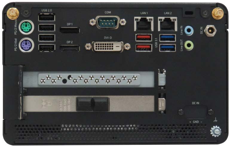
KBox B-202-CFL - User Guide, Rev 1.3

Symbols
The following symbols may be used in this user guide

                    DANGER indicates a hazardous situation which, if not avoided,
                    will result in death or serious injury.

                    WARNING indicates a hazardous situation which, if not avoided,
                    could result in death or serious injury.

                    NOTICE indicates a property damage message.

                    CAUTION indicates a hazardous situation which, if not avoided,
                    may result in minor or moderate injury.

                    Electric Shock!
                    This symbol and title warn of hazards due to electrical shocks (> 60 V) when touching
                    products or parts of products. Failure to observe the precautions indicated and/or
                    prescribed by the law may endanger your life/health and/or result in damage to your
                    material.

                    ESD Sensitive Device!
                    This symbol and title inform that the electronic boards and their components are sensitive
                    to static electricity. Care must therefore be taken during all handling operations and
                    inspections of this product in order to ensure product integrity at all times.

                    HOT Surface!
                    Do NOT touch! Allow to cool before servicing.

                    Laser!
                    This symbol inform of the risk of exposure to laser beam and light emitting devices (LEDs)
                    from an electrical device. Eye protection per manufacturer notice shall review before
                    servicing.

                    This symbol indicates general information about the product and the user guide.
                    This symbol also indicates detail information about the specific product configuration.

                    This symbol precedes helpful hints and tips for daily use.

www.kontron.com                                                                                                      // 6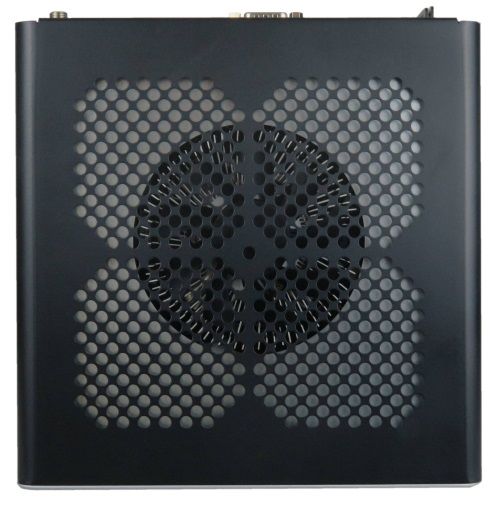
KBox B-202-CFL – User Guide, Rev 1.3

For Your Safety
Your new Kontron product was developed and tested carefully to provide all features necessary to ensure its
compliance with electrical safety requirements. It was also designed for a long fault-free life. However, the life
expectancy of your product can be drastically reduced by improper treatment during unpacking and installation.
Therefore, in the interest of your own safety and of the correct operation of your new Kontron product, you are
requested to conform with the following guidelines.

High Voltage Safety Instructions
As a precaution and in case of danger, the power connector must be easily accessible. The power connector is the
product’s main disconnect device.

                     Warning
                     All operations on this product must be carried out by sufficiently skilled personnel only.

                     Electric Shock!
                     Before installing a non hot-swappable Kontron product into a system always ensure that
                     your mains power is switched off. This also applies to the installation of piggybacks. Serious
                     electrical shock hazards can exist during all installation, repair, and maintenance operations
                     on this product. Therefore, always unplug the power cable and any other cables which
                     provide external voltages before performing any work on this product.
                     Earth ground connection to vehicle’s chassis or a central grounding point shall remain
                     connected. The earth ground cable shall be the last cable to be disconnected or the first
                     cable to be connected when performing installation or removal procedures on this product.

Special Handling and Unpacking Instruction

                     ESD Sensitive Device!
                     Electronic boards and their components are sensitive to static electricity. Therefore, care
                     must be taken during all handling operations and inspections of this product, in order to
                     ensure product integrity at all times.

                     Handling and operation of the product is permitted only for trained personnel aware of the
                     associated dangers, within a work place that is access controlled and fulfills all necessary
                     technical and environmental requirements. Follow the “General Safety Instructions for IT
                     Equipment” supplied with the product.

Do not handle this product out of its protective enclosure while it is not used for operational purposes unless it is
otherwise protected.
Whenever possible, unpack or pack this product only at EOS/ESD safe work stations. Where a safe work station is not
guaranteed, it is important for the user to be electrically discharged before touching the product with his/her hands
or tools. This is most easily done by touching a metal part of your system housing.
It is particularly important to observe standard anti-static precautions when changing piggybacks, ROM devices,
jumper settings etc. If the product contains batteries for RTC or memory backup, ensure that the product is not placed
on conductive surfaces, including anti-static plastics or sponges. They can cause short circuits and damage the
batteries or conductive circuits on the product.

www.kontron.com                                                                                                         // 7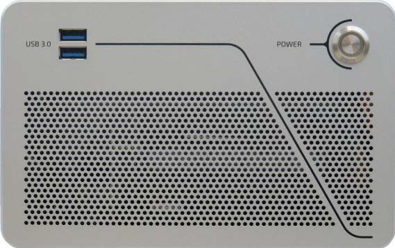
KBox B-202-CFL - User Guide, Rev 1.3
Lithium Battery Precautions
If your product is equipped with a lithium battery, take the following precautions when replacing the battery.
Danger of explosion if the battery is replaced incorrectly.
Replace only with same or equivalent battery type recommended by the manufacturer.
Dispose of used batteries according to the manufacturer’s instructions.
General Instructions on Usage
In order to maintain Kontron’s product warranty, this product must not be altered or modified in any way. Changes or
modifications to the product, that are not explicitly approved by Kontron and described in this user guide or received
from Kontron Support as a special handling instruction, will void your warranty.
This product should only be installed in or connected to systems that fulfill all necessary technical and specific
environmental requirements. This also applies to the operational temperature range of the specific board version
that must not be exceeded.
In performing all necessary installation and application operations, only follow the instructions supplied by the
present user guide.
Keep all the original packaging material for future storage or warranty shipments. If it is necessary to store or ship
the product then repack it in the same manner as it was delivered.
Special care is necessary when handling or unpacking the product. See Special Handling and Unpacking Instruction.
Quality and Environmental Management
Kontron aims to deliver reliable high-end products designed and built for quality, and aims to complying with
environmental laws, regulations, and other environmentally oriented requirements. For more information regarding
Kontron’s quality and environmental responsibilities, visit http://www.kontron.com/about-kontron/corporate-
responsibility/quality-management.
Disposal and Recycling
Kontron’s products are manufactured to satisfy environmental protection requirements where possible. Many of the
components used are capable of being recycled. Final disposal of this product after its service life must be
accomplished in accordance with applicable country, state, or local laws or regulations.
WEEE Compliance
The Waste Electrical and Electronic Equipment (WEEE) Directive aims to:
Reduce waste arising from electrical and electronic equipment (EEE)
Make producers of EEE responsible for the environmental impact of their products, especially when the product
become waste
Encourage separate collection and subsequent treatment, reuse, recovery, recycling and sound environmental
disposal of EEE
Improve the environmental performance of all those involved during the lifecycle of EEE
Environmental protection is a high priority with Kontron.
Kontron follows the WEEE directive
www.kontron.com // 8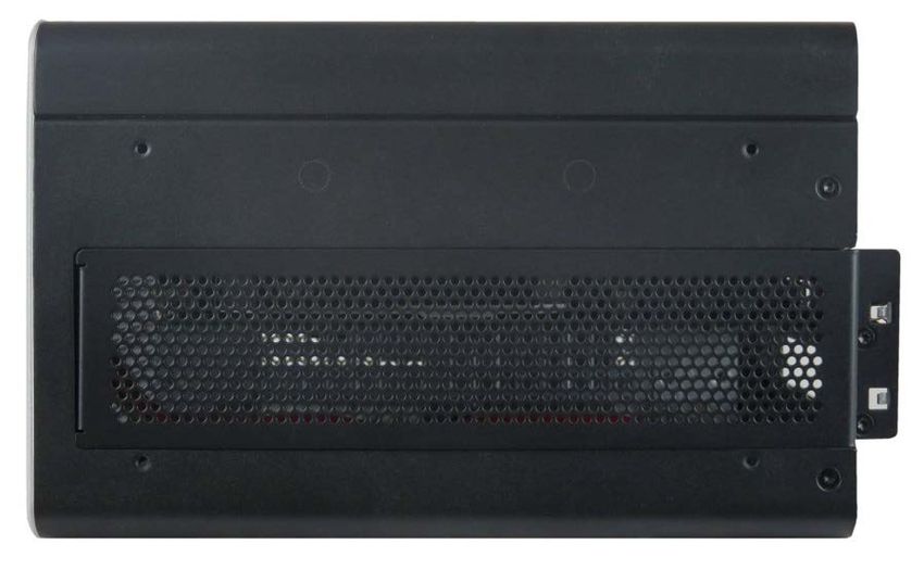
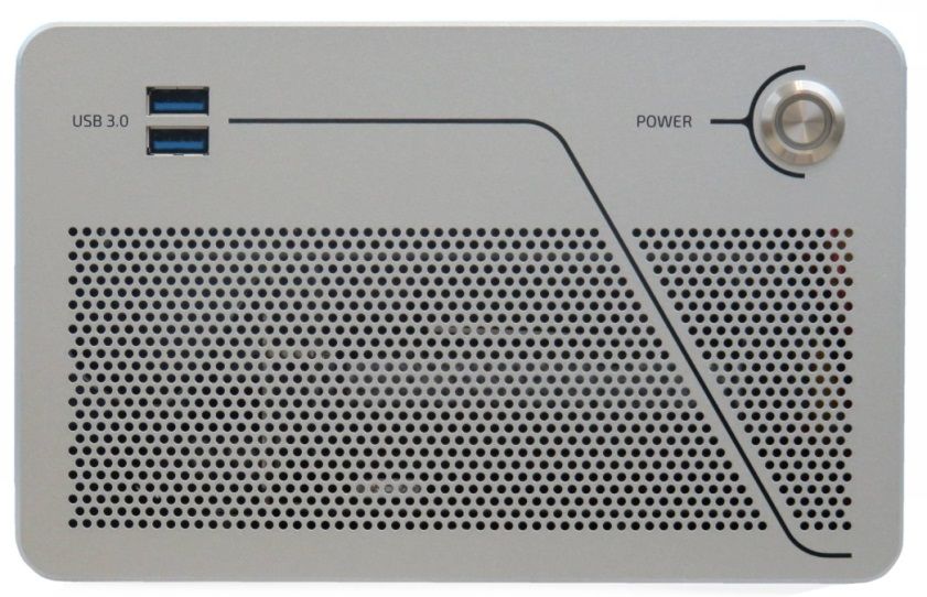
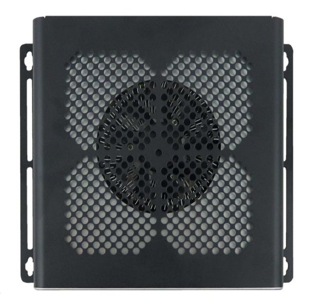
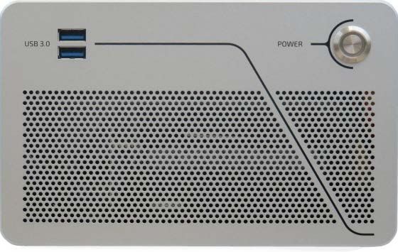
KBox B-202-CFL - User Guide, Rev 1.3

Table of Contents
Symbols .................................................................................................................................................................................................................6
For Your Safety ...................................................................................................................................................................................................7
High Voltage Safety Instructions .................................................................................................................................................................. 7
Special Handling and Unpacking Instruction ............................................................................................................................................ 7
Lithium Battery Precautions .......................................................................................................................................................................... 8
General Instructions on Usage ..................................................................................................................................................................... 8
Quality and Environmental Management ................................................................................................................................................ 8
Disposal and Recycling.................................................................................................................................................................................... 8
WEEE Compliance.............................................................................................................................................................................................. 8
Table of Contents...............................................................................................................................................................................................9
List of Tables ......................................................................................................................................................................................................11
List of Figures ....................................................................................................................................................................................................12
1/           General Safety Instructions ...........................................................................................................................................................14
1.1. Electrostatic Discharge (ESD) Precautions ....................................................................................................................................... 15
1.2. Grounding Methods .................................................................................................................................................................................. 15
1.3. Instructions for the Lithium Battery ................................................................................................................................................... 15
2/           Introduction .........................................................................................................................................................................................16
3/           Scope of Delivery ............................................................................................................................................................................... 17
3.1. Packaging ..................................................................................................................................................................................................... 17
3.2. Unpacking.................................................................................................................................................................................................... 17
3.3. Scope of Delivery ...................................................................................................................................................................................... 17
3.4. Accessories ................................................................................................................................................................................................18
3.5. Product Identification Type Label ....................................................................................................................................................... 19
4/           Product Features ............................................................................................................................................................................... 20
4.1. Front Side Features ................................................................................................................................................................................. 20
4.2. Front Side Connectors ........................................................................................................................................................................... 20
4.2.1. Power Button ......................................................................................................................................................................................... 20
4.2.2. USB 3.1 Gen 1 Port................................................................................................................................................................................. 20
4.3. Rear Panel Features ................................................................................................................................................................................ 21
4.4. Rear Panel Connectors .......................................................................................................................................................................... 23
4.4.1. Keyboard/Mouse PS/2 Connectors ............................................................................................................................................... 23
4.4.2. USB 2.0 Ports......................................................................................................................................................................................... 23
4.4.3. Display Port (DP).................................................................................................................................................................................. 23
4.4.4. DVI-D Connector .................................................................................................................................................................................. 23
4.4.5. COM Port ................................................................................................................................................................................................. 24
4.4.6. LAN Ports................................................................................................................................................................................................ 24
4.4.7. USB 3.1 Gen 2 Ports.............................................................................................................................................................................. 24
4.4.8. USB 3.1 Gen 1 Ports .............................................................................................................................................................................. 25
4.4.9. Line-IN, Line-OUT Connectors......................................................................................................................................................... 25
4.4.10. DC-IN Connector ................................................................................................................................................................................ 25
4.4.11. AC-IN (option -Smart Storage only) ............................................................................................................................................. 25
4.4.12. Potential Equalization Stud ............................................................................................................................................................ 25
4.4.13. Wi-Fi Antenna Connectors (option) ............................................................................................................................................. 26
4.5. Left and Right Side Features................................................................................................................................................................ 27
4.6. Top Cover and Bottom Side Features ............................................................................................................................................... 28
5/           Options.................................................................................................................................................................................................. 29

www.kontron.com                                                                                                                                                                                                        // 9
KBox B-202-CFL - User Guide, Rev 1.3

5.1. Expansion Options ................................................................................................................................................................................... 29
5.1.1. Drive Bay Options .................................................................................................................................................................................. 30
5.1.2. Storage Bay Options ............................................................................................................................................................................ 30
5.1.3. PCIe Slot Options .................................................................................................................................................................................... 31
5.1.4. Internal Options .................................................................................................................................................................................... 32
5.2. Power Options .......................................................................................................................................................................................... 33
6/          Accessing Components ................................................................................................................................................................... 34
6.1. Top Cover (opening and closing) ........................................................................................................................................................ 34
6.1.1. Installing and Removing an On-board mPCIe Expansion Card .............................................................................................. 36
6.1.2. Installing and Removing an On-board M.2 SSD Module.......................................................................................................... 36
6.2. Drive Bay (opening and closing) ......................................................................................................................................................... 37
6.2.1. Installing and Removing a 2.5” SSD Drive ..................................................................................................................................... 38
6.2.2. Installing and Removing the 2.5” SSD Dual M.2 RAID Module............................................................................................... 39
6.3. Expansion Door (opening and closing) ............................................................................................................................................ 42
6.3.1. Installing and Removing PCIe Expansion Cards ......................................................................................................................... 42
6.4. Storage Bay ...............................................................................................................................................................................................44
6.4.1. Installing and Removing Storage Bay Drives .............................................................................................................................. 44
7/          Thermal Considerations ................................................................................................................................................................. 45
7.1. Active Cooling ............................................................................................................................................................................................ 45
7.2. Mount Orientation ................................................................................................................................................................................... 46
7.3. Minimum Clearance (Keep Out Area) ................................................................................................................................................ 46
7.4. Third Party Components ....................................................................................................................................................................... 46
8/          Installation Instructions ................................................................................................................................................................. 47
8.1. Chassis Feet ...............................................................................................................................................................................................48
8.1.1. Chassis Feet Mount (option) .............................................................................................................................................................48
8.2. Mounting Brackets (option) ................................................................................................................................................................. 49
8.2.1. Mounting On or Underneath a Desktop ......................................................................................................................................... 51
8.2.2. Mounting on a Wall ............................................................................................................................................................................. 52
8.3. Connecting the Wi-Fi Antenna (option) ........................................................................................................................................... 53
9/          Starting Up........................................................................................................................................................................................... 54
9.1. Connecting the 12 VDC AC/DC Power Supply.................................................................................................................................. 54
9.2. Connecting the 24 VDC Wired Power Cable (option) ................................................................................................................... 54
9.3. Connecting to the AC Connector (option) ........................................................................................................................................ 55
9.4. Power On/Off Procedure ...................................................................................................................................................................... 56
9.4.1. Forced Shutdown ................................................................................................................................................................................. 56
9.5. Operating System (OS) and Hardware Component Drivers ...................................................................................................... 56
10/         Technical Data ....................................................................................................................................................................................57
10.1. Block Diagrams ........................................................................................................................................................................................57
10.2. Technical Specification ........................................................................................................................................................................ 59
10.3. Mechanical Specification .................................................................................................................................................................... 62
10.3.1. Dimension Diagrams.......................................................................................................................................................................... 62
10.4. Environmental Specification ............................................................................................................................................................. 63
10.5. Directives and Standards .................................................................................................................................................................... 64
10.6. Power Specification .............................................................................................................................................................................. 65
10.6.1. DC-IN, 12 VDC ........................................................................................................................................................................................ 65
10.6.2. DC-IN, 24 VDC (option) ..................................................................................................................................................................... 66
10.6.3. AC-IN (option)...................................................................................................................................................................................... 66
10.6.4. Power Protection ............................................................................................................................................................................... 66
10.6.5. Power Consumption .......................................................................................................................................................................... 67

www.kontron.com                                                                                                                                                                                                 // 10
KBox B-202-CFL - User Guide, Rev 1.3

10.6.6. Potential Equalization ...................................................................................................................................................................... 67
11/          External Interface - Pin Assignments........................................................................................................................................ 68
11.1. DC-IN Power Connector Pin Assignment ........................................................................................................................................ 68
11.2. USB 3.1 Gen 1 Port & USB 3.1 Gen 2 Pin Assignment.................................................................................................................... 68
11.3. USB 2.0 Port Pin Assignment .............................................................................................................................................................. 69
11.4. LAN Connector Pin Assignment ......................................................................................................................................................... 69
11.5. Display Port (DP) V1.2 Connector Pin Assignment....................................................................................................................... 70
11.6. DVI-D Connector Pin Assignment ..................................................................................................................................................... 70
11.7. PS/2 Keyboard Connector Pin Assignment ..................................................................................................................................... 71
11.8. PS/2 Mouse Connector Pin Assignment .......................................................................................................................................... 71
11.9. Audio Line-out and Audio Line-in Connector Pin Assignment ................................................................................................. 71
11.10. Serial Port Connector Pin Assignment .......................................................................................................................................... 72
11.11. AC-IN Power Connector Pin Assignment (option) ...................................................................................................................... 72
12/          BIOS ........................................................................................................................................................................................................ 73
12.1. Starting the uEFI BIOS ........................................................................................................................................................................... 73
12.2. BIOS Update ............................................................................................................................................................................................. 74
13/          RAID.........................................................................................................................................................................................................75
13.1. Storage Bay RAID Array .........................................................................................................................................................................75
13.1.1. Storage Bay RAID Configuration ......................................................................................................................................................75
13.2. Drive Bay RAID Array ............................................................................................................................................................................ 76
13.2.1. Drive Bay RAID Configuration.......................................................................................................................................................... 76
13.2.2. Drive Bay RAID Software...................................................................................................................................................................77
13.3. Internal RAID Array................................................................................................................................................................................ 79
13.3.1. Internal RAID Array Configuration ................................................................................................................................................. 79
14/          Technical Support .............................................................................................................................................................................80
14.1. Returning Defective Merchandise .................................................................................................................................................... 80
15/          Storage, Transportation and Maintenance ..............................................................................................................................81
15.1. Storage ........................................................................................................................................................................................................81
15.2. Transportation .........................................................................................................................................................................................81
15.3. Maintenance .............................................................................................................................................................................................81
15.3.1. Replacing the Lithium Battery .........................................................................................................................................................81
16/          Warranty .............................................................................................................................................................................................. 82
16.1. Limitation/Exemption from Warranty Obligation ....................................................................................................................... 82
List of Acronyms ............................................................................................................................................................................................. 83
About Kontron ..................................................................................................................................................................................................84

List of Tables
Table 1: Scope of Delivery KBox B-202-CFL Variants ........................................................................................................................... 17
Table 2: Accessories ........................................................................................................................................................................................18
Table 3: KBox B-202-CFL Expansion Option .......................................................................................................................................... 29
Table 4: Drive Bay Options ........................................................................................................................................................................... 30
Table 5: Storage Bay Options ....................................................................................................................................................................... 31
Table 6: Expansion Slot Options .................................................................................................................................................................. 31
Table 7: On-board Expansion Options ...................................................................................................................................................... 32
Table 8: Motherboard Specification .......................................................................................................................................................... 59
Table 9: Processor Specification ................................................................................................................................................................ 59
Table 10: Storage Specification ................................................................................................................................................................... 59
Table 11: External Interface Specifications ............................................................................................................................................. 60
Table 12: Internal Expansion Sockets ........................................................................................................................................................ 61

www.kontron.com                                                                                                                                                                                                          // 11
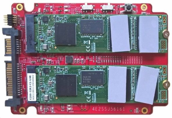
KBox B-202-CFL - User Guide, Rev 1.3

Table 13: External Expansion Slots............................................................................................................................................................. 61
Table 14: Software Specification ................................................................................................................................................................. 61
Table 15: Chassis Specification .................................................................................................................................................................... 61
Table 16: Mechanical Specifications ......................................................................................................................................................... 62
Table 17: Environmental Specification ..................................................................................................................................................... 63
Table 18: Directives and Standards Compliance ................................................................................................................................... 64
Table 19: Power supply 12 VDC AC/DC...................................................................................................................................................... 65
Table 20: Power Supply 24 VDC (variant) ............................................................................................................................................... 66
Table 21: Power supply AC-IN (variant) ................................................................................................................................................... 66
Table 22: Power Supply Protection Features (12 VDC and AC-IN) .................................................................................................. 67
Table 23: Power Consumption Estimation .............................................................................................................................................. 67
Table 24: DC Power Jack Pin Assignment ................................................................................................................................................ 68
Table 25: USB 3.1 Connector Pin Assignment ......................................................................................................................................... 68
Table 26: USB 2.0 Connector Pin Assignment ........................................................................................................................................ 69
Table 27: LAN (GbE) Connector Pin Assignment ................................................................................................................................... 69
Table 28: LAN Link Activity ........................................................................................................................................................................... 69
Table 29: Display Port (DP) Connector Pin Assignment ..................................................................................................................... 70
Table 30: DVI-D Connector Pin Assignment ........................................................................................................................................... 70
Table 31: PS/2 Keyboard Connector Pin Assignment ........................................................................................................................... 71
Table 32: PS/2 Mouse Connector Pin Assignment ................................................................................................................................ 71
Table 33: Audio Line-OUT Audio Line-IN Pin Assignment ................................................................................................................... 71
Table 34: Serial Interface COM port (RS232) Connector Pin Assignment .................................................................................... 72
Table 35: Navigation Hot Keys Available in the Legend Bar .............................................................................................................. 74
Table 36: Storage Bay RAID Array ...............................................................................................................................................................75
Table 37: Drive Bay RAID ............................................................................................................................................................................... 76
Table 38: RAID Module Jumper Settings .................................................................................................................................................. 76
Table 39: S.M.A.R.T. Information Memory Attributes Examples...................................................................................................... 78
Table 40: Notifications Examples .............................................................................................................................................................. 78
Table 41: Event List Examples ..................................................................................................................................................................... 78
Table 42: Internal RAID .................................................................................................................................................................................. 79
Table 43: List of Acronyms........................................................................................................................................................................... 83

List of Figures
Figure 1: KBox B-202-CFL .............................................................................................................................................................................. 16
Figure 2: Type Labels....................................................................................................................................................................................... 19
Figure 3: Front Panel (Smart, Value and Smart Storage) ................................................................................................................... 20
Figure 4: Rear Panel (Smart, Value and Smart Storage variants) .................................................................................................... 21
Figure 5: Rear Panel KBox B-202-CFL Smart .......................................................................................................................................... 21
Figure 6: Rear Panel KBox B-202-CFL Value .......................................................................................................................................... 22
Figure 7: Rear Panel KBox B-202-CFl Smart Storage .......................................................................................................................... 22
Figure 8: Wi-Fi Antenna................................................................................................................................................................................. 26
Figure 9: Left Side and Right Side ............................................................................................................................................................... 27
Figure 10: Top View ......................................................................................................................................................................................... 28
Figure 11: Bottom View ................................................................................................................................................................................... 28
Figure 12: Drive Day Options ........................................................................................................................................................................ 30
Figure 13: Storage Bay with Dual Removable 2.5” SSDs ..................................................................................................................... 30
Figure 14: Expansion Slot ............................................................................................................................................................................... 31
Figure 15: Power Connections Options ..................................................................................................................................................... 33
Figure 16: Holding Brackets .......................................................................................................................................................................... 35
Figure 17: Drive Bay Cover Rear Side ......................................................................................................................................................... 37
Figure 18: Drive Bay Cover Top Side .......................................................................................................................................................... 37
Figure 19: External Drive Bay with 2.5” SSD Drive................................................................................................................................. 38
Figure 20: 2.5” SSD dual RAID M.2 Module .............................................................................................................................................. 39
Figure 21: Drive Bay with 2.5” SSD dual M.2 RAID Module ................................................................................................................. 40
Figure 22: PCIe Expansion Card Screws ................................................................................................................................................... 42

www.kontron.com                                                                                                                                                                                            // 12
KBox B-202-CFL - User Guide, Rev 1.3

Figure 23: Removing Expansion Door ....................................................................................................................................................... 42
Figure 24: PCIe Slot Front Pin ...................................................................................................................................................................... 43
Figure 25: PCIe Expansion Slot Holding Latch ........................................................................................................................................ 43
Figure 26: Expansion Door............................................................................................................................................................................ 43
Figure 27: Storage Bay with Removable Drives ....................................................................................................................................44
Figure 28: Storage Bay Tray.........................................................................................................................................................................44
Figure 29: Air-intake Ventilation Openings ............................................................................................................................................. 45
Figure 30: Air-output Ventilation Openings............................................................................................................................................ 45
Figure 31: Position of Chassis Feet ............................................................................................................................................................48
Figure 32: Chassis Feet Mount Option ......................................................................................................................................................48
Figure 33: Mounting Bracket........................................................................................................................................................................ 49
Figure 34: Keep Out Areas – with Top Cover facing the Mount Surface ....................................................................................... 50
Figure 35: Keep Out Areas – with Bottom Side facing the Mount Surface ................................................................................... 50
Figure 36: Mounting Brackets on a Desktop/Mount Surface ............................................................................................................ 51
Figure 37: Mounting Brackets -Underneath a Desktop/Mount Surface ........................................................................................ 51
Figure 38: Mounting Brackets Wall Mount Options with Bottom Side facing the Mounting Surface................................. 52
Figure 39: Mounting Brackets Wall Mount Options with Top Cover facing the Mounting Surface ..................................... 52
Figure 40: 24 VDC Wired Power Cable...................................................................................................................................................... 55
Figure 41: Block Diagram of KBox B-202-CFL Smart Variant without Wi-Fi ................................................................................57
Figure 42: Block Diagram of KBox B-202-CFL Value Variant without Wi-Fi................................................................................ 58
Figure 43: Dimensions Front Panel ........................................................................................................................................................... 62
Figure 44: Dimensions Rear Panel ............................................................................................................................................................. 62
Figure 45: Dimensions Top Cover .............................................................................................................................................................. 62
Figure 46: Dimensions Bottom Side .......................................................................................................................................................... 62
Figure 47: Dimensions Right Side ............................................................................................................................................................... 63
Figure 48: Dimensions Left Side ................................................................................................................................................................. 63
Figure 49: Dimensions with Mounting Brackets ................................................................................................................................... 63
Figure 50: KBox B-202-CFL Smart Storage RAID ...................................................................................................................................75
Figure 51: 2.5” SSD dual RAID M.2 Module Settings .............................................................................................................................. 76

www.kontron.com                                                                                                                                                                                     // 13
You can also read