KIRKMANSVILLE-CLIFTY CITY, KENTUCKY POWER SUPPLY IMPROVEMENT PROJECT
←
→
Page content transcription
If your browser does not render page correctly, please read the page content below
Document Type: EA-Administrative Records
                                   Index Field:    Final Environmental Document
                                   Project Name:   Kirkmansville-Clifty City Power
                                                   Improvement Project
                                   Project Number: 2004-153

                         FINAL ENVIRONMENTAL ASSESSMENT

KIRKMANSVILLE–CLIFTY CITY, KENTUCKY
POWER SUPPLY IMPROVEMENT PROJECT
 Christian, Muhlenburg, and Todd Counties, Kentucky

                              TENNESSEE VALLEY AUTHORITY

                                                       FEBRUARY 2005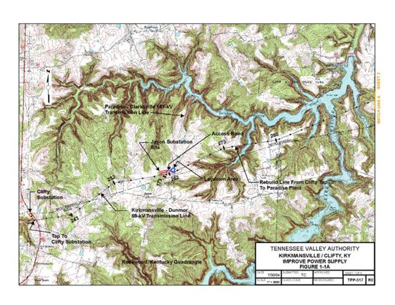
Page intentionally blank
Contents

                                              TABLE OF CONTENTS

1.           PURPOSE OF AND NEED FOR ACTION ...........................................................................1
     1.1.       Proposed Action: Improve Power Supply..........................................................................1
     1.2.       Need ................................................................................................................................1
     1.3.       Objectives of the Proposed Power Supply Improvement Project .......................................1
     1.4.       Decisions to be Made.......................................................................................................6
     1.5.       Public Involvement ...........................................................................................................6
     1.6.       Necessary Permits or Licenses ........................................................................................6
2.           ALTERNATIVES INCLUDING THE PROPOSED ACTION ..................................................9
     2.1.    Introduction ......................................................................................................................9
     2.2.    Alternatives ......................................................................................................................9
       2.2.1. The No Action Alternative – Do Not Upgrade Transmission Line ...................................9
       2.2.2. Action Alternative – Build Two New Substations and Rebuild 23 Miles
                of 69-kV Transmission Line...........................................................................................9
       2.2.3. Alternative Eliminated From Detailed Study – Rebuild the Entire
                Hopkinsville-Paradise 69-kV Transmission Line ..........................................................10
     2.3.    Description of Construction, Operation and Management of the
             Proposed 69-kV Transmission Line and Substations ......................................................10
       2.3.1. Transmission Line Structures and Conductors ............................................................10
       2.3.2. Right-of-Way Clearing.................................................................................................11
       2.3.3. Transmission Line Access Roads ...............................................................................12
       2.3.4. Transmission Line Construction Assembly Areas ........................................................12
       2.3.5. Transmission Line Conductor and Ground Wire Installation.........................................13
       2.3.6. Transmission Line Inspection......................................................................................13
       2.3.7. Vegetation Management .............................................................................................13
       2.3.8. Substation Site Preparation.........................................................................................14
       2.3.9. Substation Structures and Equipment .........................................................................14
     2.4.    Project Siting Alternatives...............................................................................................15
     2.5.    The Preferred Alternative................................................................................................15
3.           AFFECTED ENVIRONMENT.............................................................................................17
     3.1.       Terrestrial Ecology - Plants.............................................................................................17
     3.2.       Terrestrial Ecology - Animals..........................................................................................18
     3.3.       Aquatic Ecology .............................................................................................................20
     3.4.       Recreation and Managed Areas .....................................................................................21
     3.5.       Wetlands........................................................................................................................22
     3.6.       Floodplains.....................................................................................................................24
     3.7.       Surface Water ................................................................................................................24
     3.8.       Groundwater ..................................................................................................................26
     3.9.       Archaeology ...................................................................................................................27
     3.10.      Visual.............................................................................................................................28
     3.11.      Prime Farmland..............................................................................................................29
4.           ENVIRONMENTAL CONSEQUENCES .............................................................................31
     4.1.    Terrestrial Ecology - Plants.............................................................................................31
       4.1.1. No Action Alternative ..................................................................................................31

                                                Final Environmental Assessment                                                                       i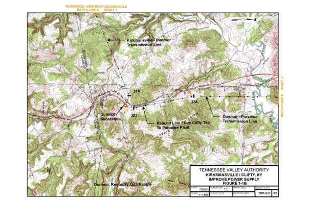
Kirkmansville-Clifty Power Supply Improvement Project

       4.1.2. Action Alternative ....................................................................................................... 31
     4.2.    Terrestrial Ecology - Animals ......................................................................................... 31
       4.2.1. No Action Alternative.................................................................................................. 31
       4.2.2. Action Alternative ....................................................................................................... 31
     4.3.    Aquatic Ecology............................................................................................................. 32
       4.3.1. No Action Alternative.................................................................................................. 32
       4.3.2. Action Alternative ....................................................................................................... 32
     4.4.    Recreation and Managed Areas..................................................................................... 34
       4.4.1. No Action Alternative.................................................................................................. 34
       4.4.2. Action Alternative ....................................................................................................... 34
     4.5.    Wetlands ....................................................................................................................... 34
       4.5.1. No Action Alternative.................................................................................................. 34
       4.5.2. Action Alternative ....................................................................................................... 34
     4.6.    Floodplains .................................................................................................................... 35
       4.6.1. No Action Alternative.................................................................................................. 35
       4.6.2. Action Alternative ....................................................................................................... 35
     4.7.    Surface Water................................................................................................................ 35
       4.7.1. No Action Alternative.................................................................................................. 35
       4.7.2. Action Alternative ....................................................................................................... 35
     4.8.    Groundwater.................................................................................................................. 36
       4.8.1. No Action Alternative.................................................................................................. 36
       4.8.2. Action Alternative ....................................................................................................... 36
     4.9.    Archaeology .................................................................................................................. 37
       4.9.1. No Action Alternative.................................................................................................. 37
       4.9.2. Action Alternative ....................................................................................................... 37
     4.10. Visual ............................................................................................................................ 37
       4.10.1. No Action Alternative.................................................................................................. 37
       4.10.2. Action Alternative ....................................................................................................... 37
     4.11. Prime Farmland ............................................................................................................. 38
       4.11.1. No Action Alternative.................................................................................................. 38
       4.11.2. Action Alternative ....................................................................................................... 38
     4.12. Summary of TVA Commitments and Proposed Mitigation Measures .............................. 39
5.           LIST OF PREPARERS ..................................................................................................... 41
     5.1.       NEPA Project Management ........................................................................................... 41
     5.2.       Other Contributors ......................................................................................................... 41
6.           LIST OF AGENCIES AND PERSONS CONSULTED........................................................ 43

7.           SUPPORTING INFORMATION......................................................................................... 45
     7.1.       Literature Cited .............................................................................................................. 45
     7.2.       Glossary of Terms ......................................................................................................... 46

ii                                             Final Environmental Assessment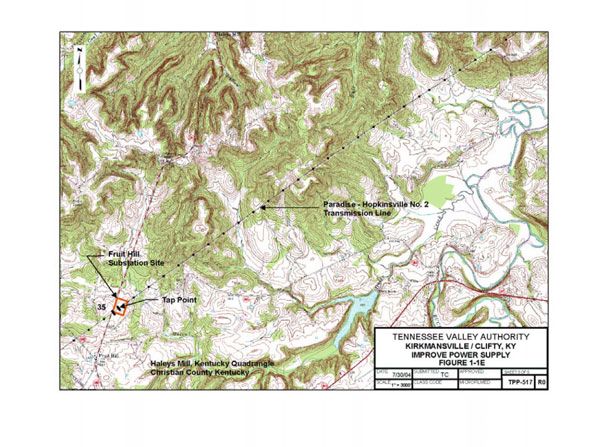
Contents

                                       LIST OF APPENDICES

APPENDIX A – CORRESPONDENCE
APPENDIX B – TENNESSEE VALLEY AUTHORITY RIGHT-OF-WAY CLEARING
             SPECIFICATIONS
APPENDIX C – TENNESSEE VALLEY AUTHORITY ENVIRONMENTAL QUALITY PROTECTION
             SPECIFICATIONS FOR TRANSMISSION LINE CONSTRUCTION
APPENDIX D – TENNESSEE VALLEY AUTHORITY TRANSMISSION CONSTRUCTION
             GUIDELINES NEAR STREAMS
APPENDIX E – TENNESSEE VALLEY AUTHORITY RIGHT-OF-WAY VEGETATION
             MANAGEMENT
APPENDIX F – TENNESSEE VALLEY AUTHORITY ENVIRONMENTAL QUALITY PROTECTION
             SPECIFICATIONS FOR TRANSMISSION SUBSTATION OR COMMUNICATIONS
             CONSTRUCTION
APPENDIX G – APPROXIMATE LOCATIONS AND LEVEL OF PROTECTION FOR
             WATERCOURSES ASSOCIATED WITH THE KIRKMANSVILLE-CLIFTY CITY 69-
             KV REBUILD AND CONSTRUCTION OF TWO SUBSTATIONS

                                             LIST OF TABLES

Table 3-1. Endangered, Threatened, and Rare Plant Species Reported
           Within 5 Miles of the Project Area ................................................................................ 18
Table 3-2. Protected Terrestrial Animal Species Reported From Muhlenberg,
           Christian, Todd, and Logan Counties, Kentucky........................................................... 19
Table 3-3. Federally and State-Listed Aquatic Animal Species Reported From
           Streams in Christian and Muhlenberg Counties, Kentucky ........................................... 21
Table 3-4. Summary of Wetland Characteristics – Kirkmansville-Clifty City
           Transmission Line Right-of-Way – October 2004 ......................................................... 23
Table 3-5. State of Kentucky Stream Use Classifications.............................................................. 24
Table 3-6. State of Kentucky 303(d) Impaired Stream Uses in the Project Area ............................ 25
Table 3-7. Soils Located in the Proposed Jason Substation Site................................................... 30
Table 3-8. Soils Located in the Proposed Fruit Hill Substation Site ............................................... 30

                                         Final Environmental Assessment                                                        iii
Kirkmansville-Clifty Power Supply Improvement Project
LIST OF FIGURES
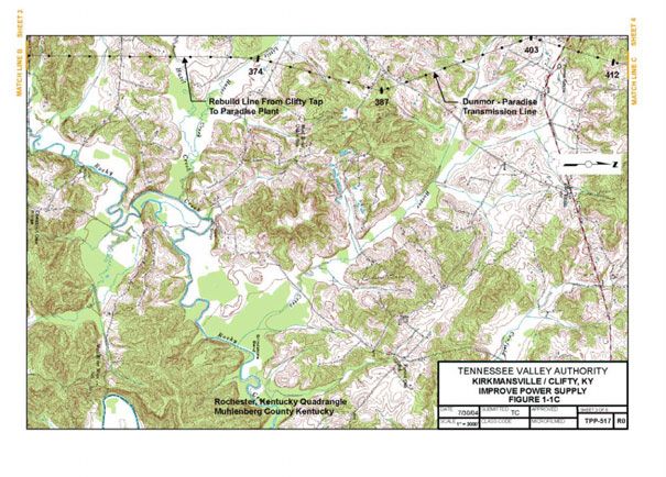
Figure 1-1A. Topographic Map Showing Location of existing Clifty Substation, the
Proposed Jason Substation Site, and a Portion of the 69-kV
Kirkmansville-Dunmor Transmission Line Proposed to be Rebuilt ........................... 2
Figure 1-1B. Topographic Map Showing Location of Existing Dunmor Substation and
a Portion of the 69-kV Dunmor-Paradise Transmission Line Proposed
to be Rebuilt ........................................................................................................... 3
Figure 1-1C. Topographic Map Showing Location of a Portion of the 69-kV
Kirkmansville-Dunmor Transmission Line Proposed to be Rebuilt ........................... 4
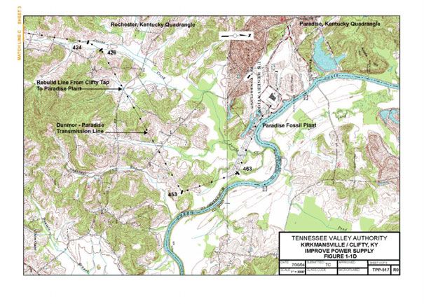
Figure 1-1D. Topographic Map Showing Location of Paradise Fossil Plant
and a Portion of the 69-kV Kirkmansville-Dunmor Transmission Line
Proposed to be Rebuilt ........................................................................................... 5
Figure 1-1E. Topographic Map Showing Location of Proposed 161-26-kV Fruit Hill Substation.... 7
Figure 2-1. Single-Pole 69-kV Transmission Structure ............................................................ 11
iv Final Environmental AssessmentChapter 1
CHAPTER 1
1. PURPOSE OF AND NEED FOR ACTION
1.1. Proposed Action: Improve Power Supply
The Tennessee Valley Authority (TVA) is proposing to improve the power supply in
Christian, Muhlenberg, and Todd Counties, Kentucky. The proposed action would include
the following component actions:
• Retire the Kirkmansville 69-kilovolt (kV) Substation and replace it by constructing a
new 161-26-kV substation to be known as the Fruit Hill Substation
• Construct a new 161-69-kV substation, i.e., the Jason Substation, to add another
69-kV power source in the area
• Rebuild a 23-mile portion of the Paradise-Hopkinsville 69-kV Transmission Line
from the Clifty Substation tap (i.e., connection point) to the Paradise Fossil Plant
(PAF)
1.2. Need
The Paradise-Hopkinsville 69-kV Transmission Line supplies electric power to TVA’s
Kirkmansville and Dunmor 69-kV Substations and to the Clifty and Ennis 69-kV
Substations, which are owned by Pennyrile Rural Electric Cooperative Corporation (RECC).
The entire line is 45.7 miles long and is constructed mainly with wood poles, wood
crossarms, and pin-type insulators, which are all at the end of their useful lives. The line
has had 80 interruptions over the last 5 years, and the cause of many of the interruptions
cannot be explained. Because of the distance involved and the electrical load on the line,
voltage fluctuations have been excessive for the Kirkmansville and Clifty Substations. The
line performance is one of the worst on the TVA system and does not meet service quality
standards. The Kirkmansville 69-kV Substation is also nearing the end of its useful life.
1.3. Objectives of the Proposed Power Supply Improvement Project
To improve the power supply for the Clifty, Dunmor, and Ennis delivery points, TVA would
retire and rebuild that portion of the Paradise-Hopkinsville 69-kV Transmission Line from
the Clifty Substation tap to the PAF using the existing right-of-way. The portion of the
transmission line that would be rebuilt includes the Kirkmansville-Dunmor 69-kV
Transmission Line running from the Clifty Substation to the Dunmor Substation and the
Dunmor-Paradise 69-kV Transmission Line from the Dunmor Substation to PAF. Maps of
the area are provided as Figures 1-1A through 1-1D. Plans for the rebuilt transmission line
call for construction to start in October 2006 and the line to be in service by February 2008.
The new line would be constructed using steel-pole structures on the centerline of the
existing 75-foot-wide right-of-way. At places where the line changes direction, TVA may
have to acquire additional rights for guys used to support the poles.
Final Environmental Assessment 1Figure 1-1A. Topographic Map Showing Locations of the Existing Clifty Substation, the Proposed Jason Substation Site
and a Portion of the Kirkmansville-Dunmor 69-kV Transmission Line Proposed to be RebuiltFigure 1-1B. Topographic Map Showing Locations of the Existing Dunmor Substation and a Portion of the 69-kV Dunmor-
Paradise Transmission Line Proposed to be RebuiltFigure 1-1C. Topographic Map Showing Location of a Portion of the 69-kV Kirkmansville-Dunmor Transmission Line
Proposed to be RebuiltFigure 1-1D. Topographic Map Showing Location of Paradise Fossil Plant and a Portion of the 69-kV Kirkmansville-
Dunmor Transmission Line Proposed to be RebuiltKirkmansville-Clifty Power Supply Improvement Project
The new Jason 161-69-kV Substation would be located on an approximately 5-acre site at
the intersection of the Paradise-Clarksville 161-kV Transmission Line and the
Kirkmansville-Dunmor 69-kV Transmission Line. The Jason Substation would tap (i.e.,
connect to) both these transmission lines to provide an additional strong power source on
the 69-kV line (see Figure 1-1A). To improve the power supply in the Kirkmansville area,
the existing Kirkmansville 69-kV Substation would be retired, and the load would be shifted
to the 161-kV system. A new delivery point for Pennyrile RECC would be established in
Christian County, Kentucky, by tapping the Paradise-Hopkinsville No. 2 161-kV
Transmission Line near Structure 35 and constructing a new substation. This new
substation, known as the Fruit Hill 161-26-kV Substation, would be located adjacent to the
line on an approximately 11-acre site (see Figure 1-1E).
1.4. Decisions to be Made
The primary decisions before TVA are whether to rebuild a portion of 69-kV transmission
line, retire a substation, and construct two new substations to improve the electrical service
in this portion of the Pennyrile RECC service area. A detailed description of the alternatives
is provided in Section 2.2.
1.5. Public Involvement
The following federal and state agencies have been contacted to date concerning this
project by TVA:
• The Kentucky Department of Environmental Protection
• The Kentucky State Historic Preservation Officer (SHPO)
• The Natural Resources Conservation Service
This proposal was reviewed for compliance with Executive Order (EO) 11988 (Floodplain
Management), EO 11990 (Protection of Wetlands), Farmland Protection Policy Act,
National Historic Preservation Act (NHPA), Endangered Species Act, Section 404 of the
Clean Water Act, and EO 12372 (Intergovernmental Review). Correspondence received
related to this coordination is contained in Appendix A.
Because TVA holds an existing right-of-way for the 69-kV transmission line, public meetings
were not held. The property owners would be sent a letter notifying them of TVA’s plan to
rebuild these facilities. The owners of the two proposed substation site properties were
contacted individually about purchase of the sites. Both owners indicated willingness to
consider selling the needed sites to TVA.
1.6. Necessary Permits or Licenses
A permit would be required from the state of Kentucky for construction site storm water
discharge for substation construction and rebuilding the transmission line. TVA's
Substation Construction organization would prepare the required erosion and sedimentation
control plans and coordinate them with the appropriate state and local authorities. A permit
would also be required for burning trees and other combustible materials removed during
transmission line construction.
6 Final Environmental AssessmentFigure 1-1E. Topographic Map Showing Location of Proposed 161-26-kV Fruit Hill Substation
Page intentionally blank
Chapter 2

                                     CHAPTER 2

2.     ALTERNATIVES INCLUDING THE PROPOSED ACTION

2.1.   Introduction
This chapter includes a description of two alternatives, i.e., a No Action Alternative and an
Action Alternative. Also, an alternative that was eliminated from further consideration is
described in this chapter. Background information about the construction, operation, and
management of the proposed transmission line and substations is also provided below.
Project siting alternatives are described, and the preferred alternative is identified. In
addition, mitigation measures that would be implemented to prevent or reduce potential
adverse environmental effects are listed.

2.2.   Alternatives
2.2.1. The No Action Alternative – Do Not Upgrade Transmission Line
Under the No Action Alternative, TVA would not upgrade the 69-kV transmission system or
construct two new substations in the area. As a result, the large number of service
interruptions to Pennyrile RECC would continue, and large voltage swings on the 69-kV
system in the area would likely continue to occur.

2.2.2. Action Alternative – Build Two New Substations and Rebuild 23 Miles of 69-kV
        Transmission Line
Under the Action Alternative, TVA would retire the Kirkmansville 69-kV Substation and
construct the new Fruit Hill 161-26-kV Substation to serve the same Pennyrile RECC
electric power load. The new substation would be a slack-span tap with enhanced
sectionalizing switches in the Paradise-Hopkinsville No. 2 161-kV Transmission Line. TVA
would construct the Jason 161-69-kV Substation adjacent to the Paradise-Clarksville 161-
kV Transmission Line. The Jason Substation would have a slack-span tap to the Paradise-
Clarksville Line, and the substation would have enhanced sectionalizing switches. The
Paradise-Hopkinsville 69-kV Transmission Line also borders this site and would be looped
into the substation. TVA would rebuild the Paradise-Hopkinsville 69-kV Transmission Line
from the Clifty tap to the PAF.

With the retirement of the Kirkmansville Substation, the electrical load from this substation
would be shifted to the more reliable and efficient 161-kV substation at Fruit Hill. This
leaves no load on the 24-mile section between Hopkinsville and the Clifty tap. The switch
at Clifty toward Hopkinsville would normally be open, and the Hopkinsville feed would be
used as backup. The Jason 161-69-kV Substation would be a strong, reliable source for
the Clifty Substation about 2 miles away, as well as the Dunmor Substation, which is
located about 5.5 miles away. The Dunmor tap sectionalizing switch toward Paradise
would be vacuum enhanced and operated normally open toward Paradise. The Ennis
Substation would normally be fed from Paradise, which is about 6 miles away.
Implementation of this alternative would meet the growing power needs in the area, reduce
service interruptions, eliminate voltage fluctuations, and provide capacity for growth of the
electrical load.

                              Final Environmental Assessment                                    9
Kirkmansville-Clifty Power Supply Improvement Project
2.2.3. Alternative Eliminated From Detailed Study – Rebuild the Entire Hopkinsville-
Paradise 69-kV Transmission Line
One option considered was to rebuild the 45.7-mile-long Paradise-Hopkinsville 69-kV
Transmission Line to 161-kV standards and operate the line at 69-kV. To address
decreases in voltage, TVA would add two 2.1 megaVAR (MVAR) 13-kV capacitor banks at
the Clifty 69-kV Substation. Installation of the new line could alleviate the outage problems
occurring from unknown sources, and the installation of the capacitor bank in the middle of
the line would likely reduce voltage fluctuations to an acceptable level. However, the long
length of the transmission line would continue to make it susceptible to outages due to
additional line exposure. The ability to serve load growth from additional power demands is
also limited at 69-kV, as the line would be near its capacity at this voltage. Additionally,
with no voltage increase in this transmission system, the anticipated load growth within the
service area is expected to develop overload conditions within a few years even with the
implementation of this alternative. This would result in the eventual need to upgrade the
line and the tapped substations to 161-kV operation. The cost of the initial upgrade would
be greater, and performance would be less than that expected under the Action Alternative.
Consequently, TVA determined that this alternative would not address the reliability or
capacity concerns in the Pennyrile RECC service area, and this alternative was eliminated
as a viable option.
2.3. Description of Construction, Operation and Management of the
Proposed 69-kV Transmission Line and Substations
2.3.1. Transmission Line Structures and Conductors
The existing pin-insulator, wood-pole transmission line would be demolished. Wood poles,
which have been treated with creosote, would be removed and made available to the public
for reuse. TVA requires persons obtaining used poles to sign an acknowledgement. TVA
also supplies these secondary users with a consumer information sheet that provides
guidelines for handling treated wood and advises against the use of treated wood for
residential uses or other uses where treated wood could come into direct contact with the
skin. Users are also warned that treated wood should not be burned or used in situations
where animals could lick or bite it or where it could contaminate feedstocks. Any remaining,
unclaimed poles would be sawed into manageable lengths and transported to appropriate
landfills for disposal. Poles disposed of in this manner are not considered a hazardous
waste and may be managed in a waste management facility authorized under state and
local law to handle this material. Insulator pins on the existing transmission line may
contain lead. Thus, all pins removed would be collected and stored in containers. Any
lead-containing materials would be recycled. Usable ceramic insulators would be reused or
disposed of as surplus material. Nonusable ceramic material would be discarded.
Conductors (the cables that carry the electrical current) are mostly aluminum, but have
steel strands imbedded in the cable for strength. Because older conductors are typically
not suitable for reuse, the metal would be scrapped and recycled. Likewise, the copper
pole-mounted ground wires and the steel overhead ground wires (also known as “static
wires”), which are used for lightning protection, would be recycled.
10 Final Environmental AssessmentChapter 2
The transmission line would be rebuilt following demolition and removal of the old
structures, conductors, and other hardware. Single steel-pole structures similar to those
shown in Figure 2-1 would support the new transmission line. Structure heights would vary
according to the terrain and would average between 65 and 75 feet. At creek or highway
crossings, taller structures may be used in order to maintain adequate clearance for the
conductors.
Figure 2-1. Single-Pole 69-kV Transmission Structure
Three conductors are required to make up a circuit in alternating current transmission lines.
For 69-kV transmission lines, each conductor is made up of a single cable. The conductors
are attached to fiberglass or ceramic insulators suspended from the structure crossarms. A
smaller, overhead ground wire is attached to the top of the structures. This ground wire
may contain fiber optic communication cables.
Poles at angles in the transmission line may require supporting guy wires. Most poles
would be imbedded directly in holes augured into the ground to a depth equal to 10 percent
of the pole’s length plus an additional 2 feet. The holes would normally be backfilled with
the excavated material. In some cases, gravel or a cement and gravel mixture might be
necessary. Some structures may be self-supporting (nonguyed) poles fastened to a
concrete foundation that is formed and poured into an excavated hole.
Equipment used during the construction phase would include trucks, truck-mounted augers
and drills, as well as tracked cranes and bulldozers. Low ground-pressure equipment
would be used in specified locations (e.g., areas with soft ground) to reduce the potential for
environmental impacts.
2.3.2. Right-of-Way Clearing
The transmission line would be rebuilt on the existing 75-foot-wide right-of-way. TVA would
purchase guy rights from landowners for the new structures as needed. The existing right-
of-way easements give TVA the right to construct, operate, and maintain the transmission
line, as well as remove “danger trees” off the right-of-way. Danger trees are those trees
that are located away from the cleared right-of-way but that are tall enough to either pass
within 5 feet of a conductor or strike a structure if they should fall toward the transmission
line. Fee title, i.e., ownership, for the land within the right-of-way remains with the
Final Environmental Assessment 11Kirkmansville-Clifty Power Supply Improvement Project landowner, and a number of activities may be continued on the property by the landowner. However, the easement agreement prohibits certain activities such as the construction of buildings and any other activities within the right-of-way that could interfere with the transmission line or create a hazardous situation. Because of the need to maintain adequate clearance between tall vegetation and transmission line conductors, as well as to provide access for construction equipment, some reclearing of the right-of-way may be required. Vegetation removal in streamside management zones (SMZs) and wetlands would be restricted to trees tall enough, or with the potential soon to grow tall enough, to interfere with conductors. Clearing in SMZs would be accomplished using hand-held equipment or remote handling equipment, such as a feller-buncher, in order to limit ground disturbance. In clearing rights-of-way, the guidelines stated in TVA’s Right-of-Way Clearing Specifications (see Appendix B) would be followed. Similarly, TVA’s Environmental Quality Protection Specifications for Transmission Line Construction (see Appendix C) and the TVA Transmission Construction Guidelines Near Streams (Appendix D) would guide transmission line construction activities. Also, any danger trees would be removed. Subsequent to clearing and construction, the right-of-way would be restored as much as is possible to its state prior to construction. Pasture areas would be reseeded with suitable grasses. Wooded areas would be restored using native grasses and other low-growing species. Erosion controls would remain in place until the plant communities become fully established. Streamside areas would be revegetated as described in Appendices B through D. 2.3.3. Transmission Line Access Roads Permanent access roads already established for this existing right-of-way would be used for vehicle access to each structure and other points along the right-of-way. Some necessary improvements would be made to these access roads. However, a few temporary access roads would also be needed in some areas to allow equipment access. TVA would obtain the necessary rights for these access roads from landowners. Existing roads, including farm and field roads, some of which may need upgrading, would be used where possible. New access roads would be located on the right-of-way wherever possible, and these would be designed to avoid severe slope conditions and to minimize stream crossings. New access roads would be about 20 feet wide and surfaced with dirt or gravel. Fifty access roads have been identified along the proposed transmission line and were included in the environmental field review. Culverts and other drainage devices, fences, and gates would be installed as necessary. Culverts installed in any permanent streams would be removed following construction. However, in wet-weather conveyances, they would be left or removed depending on the wishes of the landowner or any permit conditions that might apply. New temporary access roads would be restored to preconstruction conditions. If graveled, the gravel on the temporary access roads would be removed, and the area would be planted with native, noninvasive seed mixtures following construction. 2.3.4. Transmission Line Construction Assembly Areas Two construction assembly areas would be required for worker assembly, vehicle parking, and material storage. One of the sites selected is in a graveled storage yard on the PAF reservation. This site, which has served previously as a construction laydown area, was chosen because of its convenient location and because it is a secure site for storage of 12 Final Environmental Assessment
Chapter 2

equipment and materials. It would be used primarily during the transmission line rebuild.
Because the proposed action would not change this area from its current use, the proposed
use of this area would result in no additional environmental effects. Thus, further
environmental analysis of this site was not warranted. The other assembly area, which
would be used during the Jason Substation construction, is located along the access road
to the Jason Substation site. This construction assembly area, approximately 5 acres in
size, would be leased for the duration of the construction period. It was chosen because of
its proximity to the Jason site and because it was near a roadway that could accommodate
heavy loads of equipment. This site consists of a gently sloping, previously cleared
pastureland near the transmission line (see Figure 1-1A). Depending on site conditions,
some minor grading and installation of drainage structures may be required. The area
would be graveled and fenced to accommodate trailers used during the construction
process for material storage and for temporary office space. Following the completion of
construction activities, all trailers, unused materials, and construction debris would be
removed from the site. Removal of the fence and restoration of the site would be at the
discretion of the landowner.

2.3.5. Transmission Line Conductor and Ground Wire Installation
Reels of conductor and ground wire would be delivered to various staging areas along the
right-of-way, and temporary clearance poles would be installed at road and railroad
crossings to reduce interference with traffic. Installation of conductors would begin with a
small rope being pulled from structure to structure. This rope would then be connected to
the conductor and ground wire and used to pull them through pulleys suspended from the
insulators mounted on the structures. A bulldozer and specialized tensioning equipment
would be used to pull conductors and ground wires to the proper tension. Finally, the wires
would be clamped to the insulators, and the pulleys would be removed.

2.3.6. Transmission Line Inspection
Periodic inspections of 69-kV transmission lines are performed from the ground and by
aerial surveillance from a helicopter. These inspections, which occur on approximately 5-
year cycles after operation begins, are conducted to locate damaged conductors,
insulators, or structures, and to detect any abnormal conditions that might hamper the
normal operation of the line or adversely impact the surrounding area. During these
inspections, the condition of vegetation within the right-of-way, as well as the area
immediately adjoining the right-of-way, is noted. These observations are then used to plan
corrective maintenance and routine vegetation management.

2.3.7. Vegetation Management
Management of vegetation along the right-of-way would be necessary to ensure access to
structures and to maintain an adequate distance between transmission line conductors and
vegetation. For a 69-kV transmission line, National Electric Safety Code standards require
a minimum clearance of 19.1 feet.

Management of vegetation along the right-of-way would consist of two different activities:
namely, the felling of danger trees adjacent to the cleared right-of-way, and the control of
vegetation within the cleared right-of-way.

An integrated vegetation management approach would be used to control vegetation within
the cleared right-of-way. This approach would encourage low-growing plant species and
discourage tall-growing plants. A plan for reclearing vegetation would be developed for

                              Final Environmental Assessment                                   13
Kirkmansville-Clifty Power Supply Improvement Project each transmission line segment based on the results of the periodic inspections described above. The two principal management techniques are mechanical mowing, using tractor- mounted rotary mowers, and herbicide application. Herbicides are normally applied in areas where heavy growth of woody vegetation is occurring on the right-of-way and where mechanical mowing is not practical. Herbicides would be applied selectively from the ground with backpack sprayers or vehicle-mounted sprayers. Any herbicides used would be applied in accordance with applicable state and federal laws and regulations and the commitments listed in this document. Only herbicides registered with the United States Environmental Protection Agency (USEPA) would be used. A list of the herbicides and adjuvants (ingredients added to the herbicide solution to increase its effectiveness) currently used by TVA in right-of-way management is presented in Appendix E. This list may change over time as new herbicides are developed or new information on presently approved herbicides becomes available. Other than vegetation management, little other maintenance work would normally be required. The transmission line structures and other components typically last several decades. In the event that a structure must be replaced, the structure would normally be lifted out of the ground by crane-like equipment, and the replacement structure would be inserted into the same hole or an immediately adjacent hole. Access to the structures would be on existing roads where possible. Replacement of structures may require releveling the area surrounding the replaced structures, but there would be little, if any, additional area disturbance. 2.3.8. Substation Site Preparation Both of the new substation sites would be cleared and graded to promote proper site drainage. A storm water permit would be obtained prior to grading. Best Management Practices (BMPs) as described by Muncy (1992) would be used to minimize erosion and sedimentation. Adequate fill material exists at each site to have a balanced cut and fill on the site. The substation yard would be stabilized with gravel, and the balance of the site would be revegetated. The Kirkmansville Substation would be demolished after the Fruit Hill Substation goes into service. The usable equipment would be returned to stock. Obsolete equipment and steel framework would be sent to TVA Investment Recovery and recycled or disposed of as appropriate. Spoil material would be taken to a sanitary landfill, and the site would be revegetated. 2.3.9. Substation Structures and Equipment There are no county zoning restrictions at either the Fruit Hill or Jason Substation sites. On the Fruit Hill Substation site, TVA would install a slack-span tap structure in the transmission line. Enhanced sectionalizing switches would be installed in the transmission line about 100 feet from each side of the connection point. (Sectionalizing switches are used to disconnect a particular section of transmission line.) TVA would design and construct a standard substation capable of reducing the voltage from 161 kV to 26 kV. The substation would use a steel framework and buses (solid electrical connectors). A device known as a wave trap would be used to remove remote control signals from the circuit. Circuit switchers would provide protection for the high-voltage side. Other equipment would include isolating switches, grounding, lightning protection, two 161-26-kV transformer banks, protective relays, and metering equipment. The substation would be equipped with four circuit breakers on the low-voltage (i.e., 26-kV) side of the transformers. This 26-kV 14 Final Environmental Assessment
Chapter 2

power would then be delivered to the Pennyrile RECC system. The substation would
contain System Control and Data Acquisition and communication equipment that would
allow remote operation.

At the Jason site, TVA would install a tap structure and enhanced sectionalizing switches
similar to those described above in the Paradise-Clarksville 161-kV Transmission Line and
loop the Hopkinsville-Paradise 69-kV Transmission Line into the substation. TVA would
design and construct a 161-69-kV substation.

The Dunmor 69-kV Substation tap point and sectionalizing switches would also be rebuilt
with a vacuum enhancement on the normally open switch on the Paradise side.

2.4.   Project Siting Alternatives
The proposed action involves the construction of two new substations. Because of the
nature of the project, location alternatives for the new substations were very restricted. The
substation to serve the Kirkmansville electric load would need to connect to the Paradise-
Hopkinsville No. 2 161-kV Transmission Line. Also, a prospective site would ideally have
adequate hard-surface road access to allow delivery of substation equipment. The Fruit Hill
site was the only site identified with adequate space to allow connection to the source line,
provide for installation of sectionalizing line switches, and provide enough area to allow
construction of the substation. The identified site was 11 acres in size and sowed in grass.
The topography of the site was suitable for construction, and the property owner was
actively trying to sell the parcel.

The second proposed substation (i.e., the Jason Substation) would be used to provide
another 161-69-kV power source on the 69-kV transmission line rebuilt from the Clifty tap to
the PAF. It would normally supply the Clifty 69-kV and Dunmor 69-kV Substations. To
accomplish this, the substation would need to be located adjacent to a source 161-kV
transmission line and next to the 69-kV line it would feed. There is only one such line
crossing available. This is at the intersection of the Paradise-Clarksville 161-kV
Transmission Line and the Hopkinsville-Paradise 69-kV Transmission Line near Jason,
Kentucky. The Paradise-Montgomery 500-kV Transmission Line runs parallel to the
Paradise-Clarksville Line on the east side. In order to avoid induced voltages from crossing
under the 500-kV line, the substation would have to be located on the west side of the
Paradise-Clarksville 161-kV Line. The northwest quadrant of the intersection provided the
most suitable substation site, as the southwest quadrant did not provide suitable
topography. Access to the site is available via Canyon Rim Trail, which connects to County
Road (CR) 1785.

A tap point with enhanced sectionalizing switches would be installed in the Paradise-
Clarksville 161-kV Transmission Line, and a slack-span connection would be made into the
Jason Substation site. The Hopkinsville-Paradise 69-kV Transmission Line would also be
looped into the Jason Substation site. The site is partly pastureland and woodland. The
owner indicated his willingness to sell the site to TVA.

2.5.   The Preferred Alternative
Because the service in the Kirkmansville/Clifty area is worse than TVA’s performance
criteria, TVA would implement the Action Alternative in order to bring the level of service
into the bounds of TVA’s quality standards.

                              Final Environmental Assessment                                  15
Page intentionally blank
Chapter 3

                                      CHAPTER 3

3.     AFFECTED ENVIRONMENT
The various environmental resources and aspects of the environment that could potentially
be affected by the proposed action are described below.

3.1.   Terrestrial Ecology - Plants
The Kirkmansville-Clifty City power improvement project lands lie within the Highland Rim
Section of the Interior Low Plateau Physiographic Province (Fenneman, 1938). This project
occurs in the northern portion of the Highland Rim. The project is within the Western
Mesophytic Forest Region as described by Braun (1950). Within the Western Mesophytic
Forest Region, the proposed project area occurs in the Mississippian Plateau. The western
area of the region is flat, and then becomes hilly to the east. Historically, the natural
vegetation is a mosaic of bluestem prairie and oak-hickory forest. Today, extensive
livestock grazing and tobacco, corn, soybean, and small grain farming occur.

The project lands lie entirely within an existing power line right-of-way with the exception of
access roads and two proposed substation sites, i.e., the Fruit Hill site and the Jason site.
The access roads are primarily on existing roads or through pastures and hayfields.
Existing plant communities observed on the proposed project sites and access roads
include grasses/forbs (managed pastures, old fields, and rights-of-way), cultivated fields,
and very small areas (less than 1 percent for each) of roads, fragmented dry woods, and
intermittent streams.

Approximately 80 percent of the existing right-of-way is grasses and forbs. The remainder
is almost entirely cultivated fields. The proposed Fruit Hill Substation covers 11 acres of
pastureland dominated by fescue grass. The proposed 5-acre Jason Substation site
consists of grazed woods and pasture. The nearby 5-acre construction assembly area is a
pasture.

Grasses and forbs occupy approximately 70 percent of the right-of-way. Managed
pastures, hayfields, and open rights-of-way are most prevalent. Most of these areas are
dominated by tall fescue but include Bermuda grass and broom sedge as well. The several
species of forbs that occur within this vegetation type include butterfly weed, ironweed,
goldenrod, Chinese lespedeza, Queen Anne’s lace, passionflower, daisy fleabane, and
thistle. Cultivated fields occupy approximately 30 percent of the existing right-of-way. This
community is dominated by tobacco, corn, soybean, and small grain farming.

Dry woods occur at the proposed 5-acre Jason Substation site. This site is within a forest
fragment that is open on all sides to pastureland. The forest includes white oak, southern
red oak and post oak, Virginia pine, and tulip poplar as canopy trees. The understory,
which is open due to browsing cattle, includes red maple, flowering dogwood, and black
gum.

The plant communities observed along the proposed line rebuild route, substation sites,
and access roads are common and representative of the region. No uncommon plant
communities were observed.

                              Final Environmental Assessment                                 17
Kirkmansville-Clifty Power Supply Improvement Project
A review of the TVA Natural Heritage database indicated that no plant species that are
federally listed as threatened or endangered are known within a 5-mile radius of the
proposed project areas. However, there are three plant species listed by Kentucky within a
5-mile radius (see Table 3-1).
Table 3-1. Endangered, Threatened, and Rare Plant Species Reported Within
5 Miles of the Project Area
Common Name Scientific Name Federal Status State Status
Water-purslane Didiplis diandra None Special Concern
French’s shooting star Dodecatheon frenchii None Special Concern
Ozark bunchflower Melanthium woodii None Threatened
Known protected plant species as well as federally and other state-listed species not
presently known within the 5-mile radius were sought within areas that could be impacted
by the proposed project. No federally listed or state-listed plant species were observed.
Botanical field reviews indicated the proposed project areas would not provide suitable
habitat for these or other rare plant species.
3.2. Terrestrial Ecology - Animals
The animal habitats observed in the project area have been largely altered by agricultural
and forestry practices. The two primary habitat types observed along the transmission
corridor included early successional habitats and several tracts of hardwood forests.
The corridor route consists predominantly of early successional habitats with a combination
of agricultural fields, pastures, old fields, clear-cuts, and residential areas. Wildlife species
observed during field surveys included white-tailed deer and black rat snake. Common bird
species included red-tailed hawk, turkey vulture, killdeer, barn swallow, northern
mockingbird, indigo bunting, eastern meadowlark, mourning dove, eastern bluebird, and
American goldfinch. Other species commonly found in these habitats include eastern
cottontail rabbit, house mouse, Virginia opossum, and big brown bat.
Several tracts of hardwood forest occur along the project right-of-way corridor. White-tailed
deer were observed within this habitat. Common bird species encountered included
eastern tufted titmouse, northern cardinal, yellow-billed cuckoo, American crow, blue jay,
and Carolina chickadee. Other terrestrial animals common in such forested areas include
eastern cottontail, gray squirrel, eastern chipmunk, white-footed mouse, red bat, eastern
mole, wild turkey, slimy salamander, ground skink, five-lined skink, black rat snake, and
eastern box turtle.
A review of the TVA Natural Heritage database indicated that 14 protected animal species
have been reported from Muhlenberg, Christian, Todd, and Logan Counties in Kentucky
(see Table 3-2). All 14 species are protected by the commonwealth of Kentucky.
18 Final Environmental AssessmentChapter 3
Table 3-2. Protected Terrestrial Animal Species Reported From Muhlenberg,
Christian, Todd, and Logan Counties, Kentucky
Common Name Scientific Name Federal Status State Status
Amphibians
Barking tree frog Hyla gratiosa None Special Concern
Birds
Blue-winged teal Anas discors None Endangered
Northern harrier Circus cyaneus None Endangered
Chondestes None
Lark sparrow Threatened
grammacus
Vesper sparrow Pooecetes gramineus None Endangered
Yellow-bellied sapsucker Sphyrapicus varius None Special Concern
Bachman’s warbler Vermivora bachmanii Endangered Extinct
Mammals
Southeastern bat Myotis austroriparius None Endangered
Gray bat Myotis grisescens Endangered Endangered
Indiana bat Myotis sodalis Endangered Endangered
Common shrew Sorex cinereus None Special Concern
Southeastern shrew Sorex longirostris None Special Concern
Reptiles
Eastern ribbon snake Thamnophis sauritus None Special Concern
Nerodia erythrogaster
Copper-belly water snake Partial Status Special Concern
neglecta
Barking tree frogs are associated with wetland habitats. Individuals aggregate in
permanent water during the breeding season, but spend warm months in treetops. During
dry periods or winter months, they burrow under vegetation. Although several streams
cross the project area, a minimal amount of wetland habitat exists on the project corridor.
Due to the lack of suitable habitat, this species is unlikely to inhabit the project area.
The blue-winged teal nests within the cover of grasses and other herbaceous plants within
the immediate vicinity of water bodies. This habitat does not occur within the right-of-way.
In Kentucky, northern harriers have been found to inhabit reclaimed coal mines within the
first few years after reclamation. The harriers use these areas for only a limited time of the
year. This habitat type does not exist along the right-of-way.
Lark sparrows prefer areas with extensive open ground such as would be found in dry,
rocky areas and cedar glades. They can be found in areas with scattered red cedars with a
sparsely vegetated ground cover. This habitat was not found within the transmission line
corridor.
Vesper sparrows nest in areas of well-grazed pastures containing scattered rock outcrops
and patches of bare ground having a few scattered trees for singing perches. They have
also been found to nest where row-crop fields predominate. This species rarely breeds
south of Indiana and Illinois. The particular habitat type for this species is uncommon to
nonexistent along the transmission line.
Final Environmental Assessment 19Kirkmansville-Clifty Power Supply Improvement Project Yellow-bellied sapsuckers and Bachman’s warblers are not expected to exist in the project area. Yellow-bellied sapsuckers very rarely breed in the South, and they are not expected to breed in west Kentucky. Bachman’s warblers are considered extinct in Kentucky. They nest in bottomland forests along major river systems. This particular habitat type was not found along the right-of-way. Southeastern bats typically roost in caves and occasionally in trees. They forage over open water and typically roost near lakes or ponds. Gray bats roost in caves during all seasons and also tend to forage over open-water habitats. Indiana bats roost in caves during the winter and form summer roosts under the bark of living and dead trees. Their summer roosts are found in forests with an open understory usually near water. Although summer roosts have not been reported from the region, approximately 3,000 Indiana bats have been observed during winter in Bob Overton Cave in Christian County. Common shrews are found in a variety of habitats. They can mostly be found among rocks and logs in moist woods, marshy meadows, and sphagnum bogs. Southeastern shrews dwell in a variety of habitats but are mostly found in moist areas within forested or early successional habitats. Two protected snakes are listed in the study area. Eastern ribbon snakes are found within vegetation along waterways. Copper-belly water snakes prefer slow-moving waterways. 3.3. Aquatic Ecology The proposed transmission line rebuild and the two substations are located within the Green River drainage, a tributary of the Ohio River. Land use is predominantly agricultural, with some residential and forested areas. Located in the Western Coal Field Physiographic Province (also known as Shawnee Hills), this region is underlain by extensive Pennsylvanian sandstone and shale formations, and the resulting landscape is characterized by rolling hills. The Western Coal Field Province is most well known for its large coal deposits. Groundwater in this region typically flows through fractures, where flow is more abundant in valley wells than wells along ridges (Commonwealth of Kentucky, 2001). A search of the TVA Natural Heritage database indicated that several federally and state- listed aquatic animal species are known to occur in the streams or in cave systems in Christian and Muhlenberg Counties, Kentucky. These species are listed in Table 3-3 below. Field investigation of the subject right-of-way was conducted between August 23 and September 2, 2004. Overall, 102 aquatic resources were encountered; 58 were wet- weather conveyances; 9 were intermittent streams, and 35 were perennial (14 ponds and 21 perennial streams). A listing of these stream crossings is provided in Appendix G. Some of the crossings involve streams having more than one channel. In other locations, streams lie parallel to or meander within the right-of-way. Larger named streams that could be affected by the proposed transmission line rebuild are Sulfur Spring Creek, Clifty Creek, Rocky Creek, Hazel Creek, Little Hazel Creek, and Jacobs Creek. None of the sites where the transmission line crosses these streams were identified as suitable habitat for listed aquatic species. 20 Final Environmental Assessment
Chapter 3

Table 3-3.     Federally and State-Listed Aquatic Animal Species Reported From
               Streams in Christian and Muhlenberg Counties, Kentucky

Common Name              Scientific Name                Federal Status       State Status
Fish
  Chestnut lamprey       Ichthyomyzon castaneus                None        Special Concern
  Redspotted sunfish     Lepomis miniatus                      None          Threatened
  Southern cavefish      Typhlichthys subterraneus             None        Special Concern
Crayfish
  Eyeless crayfish       Orconectes pellucidus                 None        Special Concern
Mussels
 Fanshell                Cyprogenia stegaria              Endangered        Endangered
 Pocketbook              Lampsilis ovata                     None           Endangered
 Pyramid pigtoe          Pleurobema rubrum                   None           Endangered
 Purple lilliput         Toxolasma lividus                   None           Endangered
 Little spectaclecase    Villosa lienosa                     None          Special Concern

3.4.   Recreation and Managed Areas
A review of the TVA Natural Heritage database indicated that the transmission line for the
proposed Kirksmanville-Clifty City power improvement project crosses two managed areas.
One additional managed area is within 3 miles of the proposed project. No Ecologically
Significant Sites or streams on the Nationwide Rivers Inventory (NRI) are located within
3 miles of the proposed project.

The proposed transmission line rebuild begins at PAF, which is located between the
Sinclair and Ken Hopewell tracts of the Peabody State Wildlife Management Area (WMA).
The Peabody WMA in Ohio and Muhlenberg Counties, composed of six disjunct units or
tracts, is a rough terrain of reclaimed coal-mined lands with numerous excavated ridges
and water-filled strip-mine pits. Waterfowl and small and big game frequent swamplands,
high ridges, and deep pits. Fishing and hunting opportunities are excellent. The entire
60,000-acre Peabody State WMA (including three additional tracts to the west) is managed
by the Kentucky Department of Fish and Wildlife Resources. Primitive camping is allowed
on all tracts.

The Sinclair tract in Muhlenberg County is adjacent to PAF along the plant’s southern
boundary. Approximately 2.8 miles of the transmission line passes through the Sinclair
tract. This tract is a well-known bird-watching locale. Bald eagles, golden eagles, ospreys,
and snow geese have been noted at Goose Lake, which is approximately 2.0 miles
northwest of the transmission line. In summer, Bell’s vireo, willow flycatcher, and
Henslow’s sparrow come to the WMA. Winter brings shorebirds and a large raptor
population, including northern harriers and short-eared owls.

The Ken Hopewell tract in Ohio County is across the Green River from PAF, approximately
0.5 mile northeast of the plant and the transmission line right-of-way. Horseback riding is a
popular activity on trails within this tract.

Lake Malone in Muhlenberg County is managed by the Kentucky Department of Fish and
Wildlife Resources. The 826-acre lake is noted for game fish and for recreational use. The

                              Final Environmental Assessment                                21
You can also read


