KOKO LEGEND SPIROMETER - OPERATIONS MANUAL PART NUMBER 606055 DOCUMENT VERSION/REVISION 9.A - RESPITECH MEDICAL INC.
←
→
Page content transcription
If your browser does not render page correctly, please read the page content below
KoKo Legend Spirometer
          Operations Manual

              Part Number 606055

     Document Version/Revision 9.A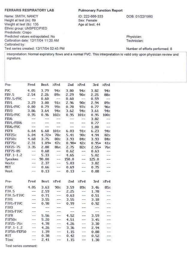
THE LEGEND OF KOKOPELLI
                                   The Southwest region of the United States is
                                   home to KoKopelli. His image can be found
                                   as a petroglyph throughout this region. Many
                                   legends surround this mysterious figure that
                                   played a prominent role in early Native
                                   American culture. He is often portrayed as
                                   the bearer of health and plenty.

         For Ferraris Respiratory, KoKopelli represents new directions of excellence in
                                 pulmonary diagnostic testing.

All rights reserved. Reproduction, adaptation, or translation without prior written permission is
prohibited, except as allowed under the copyright laws.

Caution:
Federal law restricts this device to sale by or on the order of a physician.

     is a registered trademark of Ferraris Respiratory, Inc.
KoKo is a registered trademark of Ferraris Respiratory, Inc.
KoKoMoe is a trademark of Ferraris Respiratory, Inc.
All other brand and product names mentioned in this document are trademarks and/or registered
trademarks of their respective holders.

                               KoKo Legend Operations Guide (606055 9.A)
                                                   ii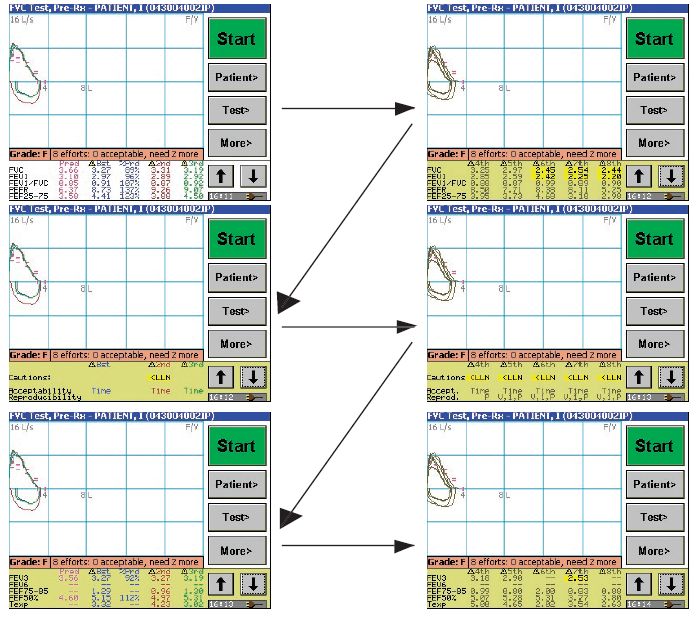
Information in this manual is subject to change without notice and does not represent a
commitment on the part of Ferraris Respiratory, Inc. The software described in this document is
furnished under a license agreement. The software may be used or copied only in accordance with
the terms of that agreement. It is against the law to copy the software on any medium except as
specifically allowed in the license agreement. No part of this manual may be reproduced or
transmitted in any form or by any means, electronic or mechanical, including photocopying and
recording, for any purpose without the express written permission of Ferraris Respiratory, Inc.
Printed and Bound in the United States of America.
Copyright © 2005 Ferraris Respiratory, Inc.

Ferraris Respiratory, a division of Ferraris Group PLC

www.ferrarisrespiratory.com

Ferraris Respiratory                          General Information: (+1) 800.574.7374 • (+1) 303.666.5555
901 Front Street,                             Fax (+1) 800.574.7373 • (+1) 303.666.5588
Louisville, Colorado, 80027, USA              Support: (+1) 800.635.3200
                                              Email: sales@pds.ferrarisgroup.com

Ferraris Respiratory Europe Ltd,              Tel: (+44) (0) 1992.526.300
Harforde Court                                Fax: (+44) (0) 1992.526.320
John Tate Road                                Support: (+44) (0) 1992.526.334
Hertford, SG13 7NW                            Email: info@fre.ferrarisgroup.com
U.K.

ZAN Messgerate GmbH,                          Tel: (+49) 097.36.8181.0
Schlimpfhofer Strasse 14                      Fax: (+49) 097.36.8181.20
D-97723 Oberthulba                            Email: zan@zan.de
Germany

Ferraris Respiratory Asia Pacific             Tel: (+852) 2562.3866
1001,10/Fl, K.Wah Centre                      Fax: (+852) 2516.5886
191 Java Road                                 Support: (+44) (0) 1992.526.334
North Point                                   Email: info@fre.ferrarisgroup.com
Hong Kong

                                   This symbol indicates that this device provides a certain level
                                   of protection against electric shock because the patient applied
                                   part is floating.
                                   This symbol indicates that the user must read and understand
                                   all instructions and warnings prior to use.

                                   This symbol indicates this software supports Class IIA
                                   equipment that complies with the Medical Devices Directive
                                   of the European Economics Community.

                                   This symbol indicates that the associated jack is for a
                                   Universal Serial Bus connection.

                                        KoKo Legend Operations Guide (606055 9.A)
                                                                 iii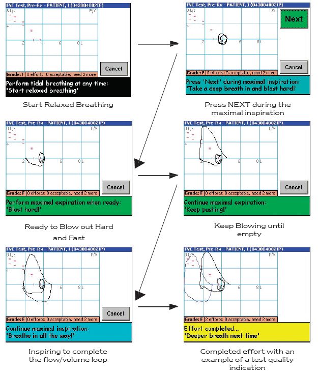
TABLE OF CONTENTS
1 QUICK START.......................................................................................................................... 9
2 INTRODUCTION.................................................................................................................... 11
2.1 USING THE MANUAL .......................................................................................................... 11
2.1.1 Documentation Conventions......................................................................................... 11
2.2 ESSENTIAL PRESCRIBING INFORMATION ............................................................................ 11
2.2.1 Device Description and Specifications ......................................................................... 11
2.2.2 Intended Use and Indications ....................................................................................... 13
2.2.3 Conformance to Standards ........................................................................................... 13
2.2.4 Warnings and Precautions............................................................................................ 13
2.2.5 Maintaining Device Effectiveness................................................................................. 14
3 GETTING STARTED ............................................................................................................. 15
3.1 UNPACKING ....................................................................................................................... 15
3.2 ASSEMBLING...................................................................................................................... 15
3.2.1 Connecting the Flow Sensor Assembly......................................................................... 15
3.2.2 Connecting the AC Adapter .......................................................................................... 16
3.2.3 Connecting to an External Printer (Optional).............................................................. 17
3.2.4 Attaching the Disposable Filter.................................................................................... 19
3.2.5 Battery Mode................................................................................................................. 20
3.2.6 Recharging the Battery ................................................................................................. 20
4 PREPARATION FOR USE .................................................................................................... 21
4.1 STARTING YOUR KOKO LEGEND SPIROMETER (POWER ON).............................................. 21
4.2 CALIBRATING THE SPIROMETER......................................................................................... 21
4.3 SETUP ................................................................................................................................ 21
4.4 ADVANCED CONFIGURATION OF THE KOKO LEGEND SPIROMETER ................................... 25
5 TESTING OPTIONS ............................................................................................................... 27
5.1 PATIENT PREPARATION ...................................................................................................... 29
5.1.1 Pre-Test Checklist......................................................................................................... 30
5.2 ENTERING PATIENT DATA ................................................................................................. 30
5.3 RECALLING PATIENT DATA ............................................................................................... 31
6 PERFORMING TESTS........................................................................................................... 33
6.1 FVC TEST (PRE-RX).......................................................................................................... 33
6.1.1 Objective of the FVC Test............................................................................................. 33
6.1.2 Performing the FVC Test.............................................................................................. 33
6.2 SVC TEST.......................................................................................................................... 34
6.2.1 Objective of the SVC Test ............................................................................................. 35
6.2.2 Performing the SVC Test .............................................................................................. 35
6.3 VIEWING IMMEDIATE TEST RESULTS ................................................................................. 37
6.3.1 QC GRADE................................................................................................................... 39
6.3.2 Interpretation Statement ............................................................................................... 39
6.4 PERFORMING THE NEXT TEST ............................................................................................ 40
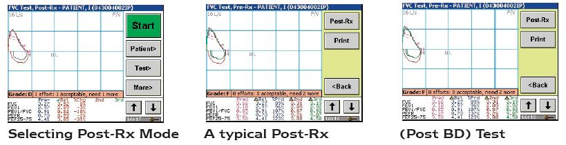
6.5 PERFORMING POST-RX TESTS ............................................................................................ 40
6.5.1 Object of the Test .......................................................................................................... 40
KoKo Legend Operations Guide (606055 9.A)
iv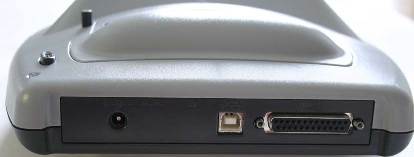
6.5.2 Performing the Test and Viewing Results..................................................................... 40
6.6 PRINTING TEST REPORTS ................................................................................................... 40
6.6.1 Estimated MVV ............................................................................................................. 41
7 MAINTENANCE ..................................................................................................................... 43
7.1.1 Calibration.................................................................................................................... 43
7.1.2 Barometric Pressure ..................................................................................................... 46
7.1.3 Printing a Calibration Report....................................................................................... 46
7.2 CLEANING .......................................................................................................................... 48
7.2.1 Cleaning the Main Unit ................................................................................................ 49
7.2.2 Cleaning the Touch Screen ........................................................................................... 49
7.2.3 Cleaning the Flow Sensor Assembly............................................................................. 49
7.2.4 Cleaning the Print Head ............................................................................................... 49
7.2.5 Removing the Pneumotach Tube................................................................................... 50
7.2.6 Cleaning the Pneumotach Tube.................................................................................... 50
7.3 MANAGING DATA ON THE MEMORY CARD ........................................................................ 50
7.3.1 Checking the Status of the Memory Card ..................................................................... 51
7.3.2 Deleting Data from the Memory Card.......................................................................... 51
7.3.3 Erasing the Memory Card ............................................................................................ 52
8 PC INTERFACE...................................................................................................................... 53
8.1 EXTENDED CONFIGURATION USING THE CONFIGURATOR PROGRAM ................................. 53
8.1.1 Accessing the Extended Configuration Options ........................................................... 53
8.2 TRANSFERRING DATA TO THE KOKO PFT SPIROMETRY SOFTWARE ................................. 55
APPENDIX A - TROUBLESHOOTING ..................................................................................... 56
APPENDIX B - GLOSSARY......................................................................................................... 57
APPENDIX C - PREDICTED NORMAL EQUATIONS........................................................... 60
APPENDIX D - INTERPRETATION .......................................................................................... 71
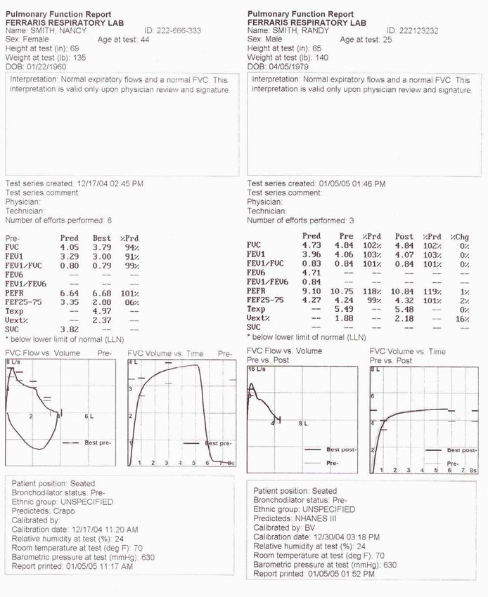
APPENDIX E - SAMPLE REPORTS .......................................................................................... 72
APPENDIX F - REFERENCES .................................................................................................... 75
APPENDIX G - MESSAGES......................................................................................................... 76
9 INDEX....................................................................................................................................... 78
Table of Figures
Figure 1 – KoKo Legend Parts ......................................................................................................... 15
Figure 2 – Handset Cable.................................................................................................................. 16
Figure 3 – External Power Supply.................................................................................................... 16
Figure 4 – Parallel Printer Compatible KoKo Legend Rear View ................................................... 17
Figure 5 – USB Printer Compatible KoKo Legend Rear View........................................................ 17
Figure 6 – Printer Cover Release Button .......................................................................................... 18
Figure 7 – Paper Feed ....................................................................................................................... 19
Figure 8 – Filter Attached to the Flow Sensor.................................................................................. 19
KoKo Legend Operations Guide (606055 9.A)
v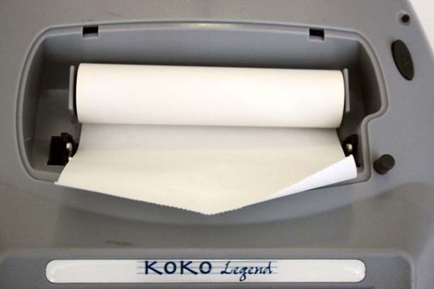
Figure 9 – Main FVC Testing Screen............................................................................................... 21
Figure 10 – Setup Screen 1/4............................................................................................................ 22
Figure 11 – Setup Screen 2/4............................................................................................................ 22
Figure 12 – Setup Screen 3/4............................................................................................................ 23
Figure 13 – Setup Screen 4/4............................................................................................................ 24
Figure 14 – FVC Options 1/3 ........................................................................................................... 27
Figure 15 – FVC Options 2/3 ........................................................................................................... 28
Figure 16 – Candle Incentive Display .............................................................................................. 28
Figure 17 – FVC Options 3/3 ........................................................................................................... 29
Figure 18 – Entering a New Patient.................................................................................................. 30
Figure 19 – Keypad........................................................................................................................... 31
Figure 20 – Select Patient Screen ..................................................................................................... 31
Figure 21 – Sample Search ............................................................................................................... 32
Figure 22 – FVC Test Screens.......................................................................................................... 34
Figure 23 – SVC Test Start Screen................................................................................................... 35
Figure 24 – Start of SVC Test .......................................................................................................... 36
Figure 25 – SVC Prompt for Maximal Inspiration ........................................................................... 36
Figure 26 – SVC Prompt for Maximal Expiration ........................................................................... 36
Figure 27 – SVC Effort Completed .................................................................................................. 37
Figure 28 – Scrolling Through Test Results Screen ......................................................................... 38
Figure 29 – Printing a Test Series..................................................................................................... 41
Figure 30 – Calibration Parameters .................................................................................................. 43
Figure 31 – Start Calibration Screen................................................................................................. 44
Figure 32 – Calibration Successful................................................................................................... 44
Figure 33 – Calibration (Cal) Check Successful .............................................................................. 45
Figure 34 – Example of a Successful Calibration............................................................................. 47
Figure 35 – Example of a Successful Calibration............................................................................. 47
Figure 36 – Cleaning the Print Head ................................................................................................ 50
Figure 37 – Memory Card Information ............................................................................................ 51
Figure 38 – Delete Test Series Screen .............................................................................................. 51
Figure 39 – Delete Patient Demographics Screen ............................................................................ 51
Figure 40 – Warning Message .......................................................................................................... 52
Figure 41 – KoKo Legend Configuration Options ........................................................................... 53
Figure 42 – Extended Configuration Options................................................................................... 54
Figure 43 – Saving Master Configuration Screen ............................................................................ 55
Figure 44 – Loading Configuration Screen ...................................................................................... 55
Figure 45 – McKay Interpretive Algorithm...................................................................................... 71
Figure 46 – Sample Internal Printer Reports .................................................................................... 72

                                           KoKo Legend Operations Guide (606055 9.A)
                                                                      vi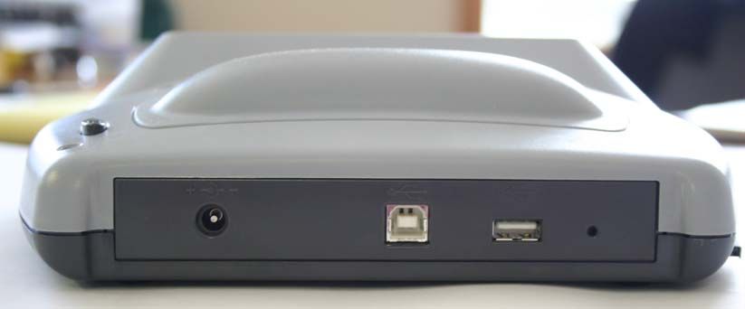
Figure 47 – Sample External Printer Report..................................................................................... 74

                                                       Table of Tables
Table 1 – Quick Start Tasks................................................................................................................ 9
Table 2 – Device Description and Specifications............................................................................. 11
Table 3 – Messages Related to Patient’s Effort................................................................................ 38
Table 4 – Quality Grades Related to Patient’s Effort ....................................................................... 39
Table 5 – Estimated Barometric Pressure vs. Altitude ..................................................................... 46
Table 6 – Troubleshooting Scenarios ............................................................................................... 56
Table 7 – Glossary ............................................................................................................................ 57
Table 8 – Messages........................................................................................................................... 76

                                           KoKo Legend Operations Guide (606055 9.A)
                                                                       vii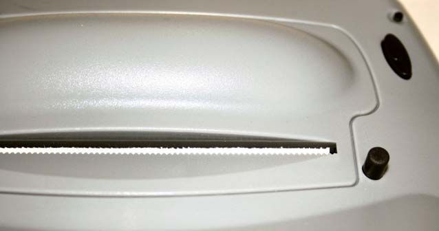
1 Quick Start
This section provides a sequence of tasks to perform to get you started using your Legend as
quickly as possible. If you need additional instructions, refer to the associated section of the
manual.
                                            Table 1 – Quick Start Tasks

Step Task                                                      Section Reference                   Starting
                                                                                                   Page
   1. Assemble the device.                                     3.2, Assembling                     15
   2. Power on the device.                                     4.1, Starting your KoKo Legend      21
                                                               Spirometer (Power On)
   3. Setup the device (e.g., date and time format, 4.3, Setup                                     21
      units of measure, protocol selection,
      language selection, etc.).
       Select            then           .
   4. Select your test options (e.g., setting testing          5, Testing Options                  27
      environmental conditions, display options,
      patient position, etc.).
       Select            then       .
   5. Calibrate the device.                                    7.1.1, Calibration                  43
       Select            then       .
   6. Enter patient data.                                      5.2, Entering Patient Data          30
       Select            then       .
   7. Perform tests.                                           6.1.2, Performing the FVC Test or   33 or 35
                                                               6.2.2, Performing the SVC Test
       Select       (starts the test identified in the
       upper left-hand of the screen); or
       and          or          , and        (starts the
       other test).
   8. Print test results.                                      6.6, Printing Test Reports          40
       Select            then           .
   9. Optionally, transfer data to a PC.                       8, PC Interface                     53

                                  KoKo Legend Operations Guide (606055 9.A)
                                                           9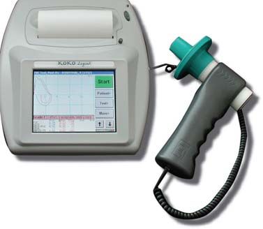
2 Introduction
Congratulations! You have purchased a quality instrument that will give you many years of
excellent service. Ferraris Respiratory’s personnel are ready to help you in any way necessary to
assure your satisfaction with your purchase. The KoKo Legend Spirometer is a desktop portable
device capable of performing both pre- and post-bronchodilator forced and slow expiratory
maneuvers and calculating the standard spirometric indices.
Please take the time to:
     • Inspect the contents of this package for completeness.
     • Read the Essential Prescribing Information, especially the Precautions.
     • Complete the enclosed warranty card.

2.1     Using the Manual
This manual will provide detailed instructions on the use of the KoKo Legend Spirometer and an
overview of related topics. The user is encouraged to supplement this manual with additional
reading in published literature. Appendix F - References of this manual provides a reference for
some additional reading material. The user instructions in the following chapters assume the user
is adequately familiar with the intended use and application of a spirometer.
2.1.1 Documentation Conventions
The following format conventions are used in this document to identify special information:
Warning statements identify conditions or practices that could result in personal injury.
Caution statements identify conditions or practices that could result in damage to equipment or
loss of data.
Variable names are enclosed in angle brackets and presented in italicized text (e.g.: ).
   Notes: The screen illustrations and the displayed data in this document are for example purposes only. They
          may differ from the screens on your PC.
          The graphical illustrations in this document are for example purposes only and the hardware
          illustrated may differ from your hardware.

2.2     Essential Prescribing Information
2.2.1   Device Description and Specifications
                                  Table 2 – Device Description and Specifications

Tests Performed:                            FVC (Pre-Post Rx), SVC
Parameters Measured:                         • Expiratory: FVC, FEV.5, FEV.5/FVC%, FEV1,
                                               FEV1/FVC%, FEV3, FEV3/FVC%, FEV6, FEV6/FVC%,
                                               FEV1/FEV6%, +PEFR, FEF25%, FEF50%, FEF75%,
                                               FEF25-75%, FEF.2-1.2, FEF75-85%, Tpeak(mSec),
                                               Vext%, Vext(L), MET(S), Texp(S), Veot(L)
                                             • Inspiratory: FIVC, FIV.5, FIV.5/FIVC, FIV1/FIVC, FIV3,
                                               FIV3/FIVC, PIFR, FIF50%, FIF25-75%, FIF.2-1.2,
                                               FIF50/FEF50, MIT(S), Tinsp(S)

                                   KoKo Legend Operations Guide (606055 9.A)
                                                          11
Table 2 – Device Description and Specifications
Pneumotach: Accuracy: < ±3% or 100 ml, whichever is greater
Flow Range: -12 to +16 L/s
Type: Flexible Variable Orifice Pneumotach
Filter Requirement: KoKoMoe (model #810000 or 819000)
Power Equipment: Supplied external 100-240 VAC Switching Power Supply /
Recharger, 12 VDC Output, 2.5 Amp; Rechargeable internal
NiMH battery.
Reproducibility: < ±0.5%
Volume Range: ±16L
Resistance: < 1.5 cmH20/L/sec when tested with KoKoMoe filter
Software Compatibility Downloadable to KoKo PFT Spirometry Software version 4.6
(build 6) or higher; operating on Windows 2000, XP or higher
Predicted Sets: Hankinson (NHANES III (USA)), Crapo 1981 (USA), Polgar
(Pediatrics (USA)), ERS 93 (ECCS), Perriera (Brazil), Gore
(Australia), Dejsomritrutai (Thai), SEPAR (Spain), Forche
(Austria), Gulsvik (Norway), Viljanen (Finland), Knudson 76
(USA), and Hedenstrom (Sweden)
Interpretation Algorithm: McKay (ATS / ARRD 1991)
Reports: Formats for both Internal and External Printers:
1. FVC Standard Best
2. FVC Pre-Post Best
3. FVC Complete Best 3
4. FVC Complete Best Pre/Post
5. FVC V/T Full Size
6. Pre-Post + V/T Full Size
7. Standard Best 3
8. Pre-Post Best 3
9. SVC Complete Best 3
10. SVC Pre-Post Best
Incentive Graphics: Photo-realistic Color Candles
KoKo Legend Operations Guide (606055 9.A)
12Table 2 – Device Description and Specifications
Connectivity: Downloadable to KoKo PFT Software via built-in USB port;
Uploadable patient demographics from KoKoPFT via built-in
USB port.
Physical Specifications Construction: High-impact Polycarbonate
Dimensions: 23.5 x 25.4 x 7.0 cm; 9.25 x 10.0 x 2.75 inches
Weight: 1.6 kg; 3.6 lbs.
Operating Environment: 10 - 40°C; 0 – 80% relative humidity non-condensing at
temperatures to 31°C
Safety: Use only supplied Class II Power adapter; Ordinary
equipment (not protected against harmful ingress of
moisture); Not suitable for use with flammable anesthetics;
Suitable for continuous use.
EMC Rating: Radiation and conducted emissions and immunity per EN
60601-1-2
Performance Standards: ATS 1994 – properly measures all 26 flow-time waveforms;
ERS; BTS; NIOSH; ACOEM
Quality standards: • Quality System Regulations: FDA QSR [21 CFR 820],
ISO 13485:1996 CMDCAS
• European Directives: MDD 93/42/EEC
• Product Standards: EN 60601-1, 60601-1-1, 60601-1-2
2.2.2 Intended Use and Indications
This device is intended to be used as a pulmonary function diagnostic testing device. The flow
sensor assembly is held by the patient, but it does not in any way interact with or influence the
patient when used as specified. This device is indicated for use in the diagnosis and monitoring of
asthma and other respiratory diseases.
2.2.3 Conformance to Standards
Ferraris Respiratory and this device conform to the following standards:
Quality System Regulations FDA QSR [21 CFR 820], ISO13485:1996 CMDCAS
European Directives MDD 93/42/EEC
Product Standards EN 60601-1, 60601-1-1, 60601-1-2
2.2.4 Warnings and Precautions
Federal Law restricts this device to sale by or on the order of a physician.
KoKo Legend Operations Guide (606055 9.A)
13CAUTION: Always use the AC adapter that accompanied the system. Using a different AC
adapter can cause permanent damage to your system.
CAUTION: Always use the USB cable that accompanied the system in order to comply with
radiation and conducted emissions and immunity per EN 60601-1-2.
WARNING: The operator must not create a “bridge” between the KoKo Legend I/O ports and the
patient by simultaneously touching both.
CAUTION: Do not attempt to wash or immerse the KoKo Legend or accessories in water or
cleaning fluid, as there are electronic components inside that will be permanently
damaged.
CAUTION: This device complies with the minimum electromagnetic compatibility requirements
of the Medical Device Directive (MDD). However, electromagnetic interference
may still be encountered. If the device is behaving erratically due to
electromagnetic interference, contact our service department (refer to page iii for
contact information).
2.2.5 Maintaining Device Effectiveness
The recommended operating conditions for the KoKo Legend Spirometer are 10° to 40°C, 0 to
80% humidity non-condensing at temperatures to 31°C, decreasing linearly to 50% relative
humidity at 40°C. The recommended transport and storage conditions are -20°C to 50 °C; 0 to
95% non-condensing humidity; -1000 to 10,000 feet or 787.9-522.7 mm Hg.
The KoKo Legend Spirometer housing may be wiped clean with a soft cloth dampened with soapy
water. Refer to the section 7, Maintenance, for complete cleaning instructions.
Your KoKo Legend Spirometer has been assembled with care and tested thoroughly to provide you
with a quality instrument for many years of use. We ask that you provide the extra effort and care
required to familiarize yourself with all of its features to assure proper and effective use.
KoKo Legend Operations Guide (606055 9.A)
143 Getting Started
This section describes the components of your KoKo Legend spirometer. We strongly recommend
that you read it before using your KoKo Legend - even if you are already familiar with spirometers.
3.1 Unpacking
When you receive your KoKo Legend, unpack it carefully, and compare the parts you have
received with the items listed below:
1 2 3
4
10
5
8 7 6
9
Figure 1 – KoKo Legend Parts
Figure Legend
1 – AC Adapter with AC Power Cord 6 – Flow Sensor Assembly
2 – KoKo Legend Desk Top Spirometer 7 – Nose Clip
3 – Printer Paper 8 – Disposable Filter
4 – KoKo Legend Operator’s Guide 9 – Optional Software Configurator
5 – Handset Cable 10 – USB Cable
Once you have checked and confirmed that your KoKo Legend is complete, read through the
following pages to learn all about your spirometer’s capabilities.
3.2 Assembling
Be sure to observe the safety precautions listed in section 2.2.4, Warnings and Precautions, of this
manual.
3.2.1 Connecting the Flow Sensor Assembly
The flow sensor assembly is connected to the desktop spirometer with the handset cable.
KoKo Legend Operations Guide (606055 9.A)
15Figure 2 – Handset Cable
The small jack located on the right side of the KoKo Legend device is used to connect the flow
sensor assembly. To connect the flow sensor assembly follow these steps:
1. Align the connector on the handset cable with the port opening labeled:
2. Push the connector into the port until it is seated.
3. Plug the other end into the matching port on the bottom of the flow sensor assembly.
3.2.2 Connecting the AC Adapter
Caution: Do not operate the KoKo Legend using any other power supply than the one provided with the
system.
The Legend is powered by an external AC adapter, which also functions as a charger for the
internal NiMH rechargeable battery.
Figure 3 – External Power Supply
Notes: Only authorized service personnel should replace the battery.
Charge the battery for approximately four hours prior to initial use if using under battery power. It is
acceptable to use the device immediately if it is plugged into AC power.
KoKo Legend Operations Guide (606055 9.A)
162
1 3
Figure 4 – Parallel Printer Compatible KoKo Legend Rear View
Figure Legend
1 Power port
2 USB port (optionally used to connect to a PC)
3 External printer port (parallel printer)
2
4
1
3
Figure 5 – USB Printer Compatible KoKo Legend Rear View
Figure Legend
1 Power port
2 USB port (optionally used to connect to a PC)
3 Reset button
4 External printer port (USB printer)
1. Plug the round end of the power adapter cable into the matching round DC power input jack
on the back panel of the KoKo Legend.
The jack is labeled:
2. Plug the AC adapter into an AC electrical outlet.
3.2.3 Connecting to an External Printer (Optional)
There are two Legend models, one has a parallel printer port and the other has a USB printer port.
Refer to Figure 4 and Figure 5.
The KoKo Legend has been designed to interface with HP printers supporting PCL 3 or later.
KoKo Legend Operations Guide (606055 9.A)
17Note: Since many printers support this character set, the Legend device has not been validated with every
model. It has been validated with the HP 5650.
1. Connect the cable to the printer.
2. Connect the other end of the printer cable to the back panel of the Legend device.
a. If you have a parallel printer compatible Legend device, plug the parallel printer
cable into the parallel printer port on the back panel of the KoKo Legend device.
The port is labeled:
b. If you have a USB printer compatible Legend device, plug the USB printer cable
into the USB printer port on the back panel of the KoKo Legend device.
The port is labeled:
3. Connect the printer to a power supply.
4. Turn on the printer.
3.2.3.1 Opening and Closing the Internal Printer Cover
To open the internal printer cover, perform the following:
1. Press the printer cover release button. The cover releases from the unit.
Release Button
Figure 6 – Printer Cover Release Button
2. Remove the cover from the unit and set aside.
3. Perform the desired maintenance.
4. Replace the cover by positioning it on to the unit. Make sure the end of the paper supply
passes through the slot in the cover. Slide the two tags on the cover into the slots on the
unit.
5. Press the door down on the doomed area until it engages.
3.2.3.2 Loading the Printer Paper
To load the paper roll for the internal printer, perform the following:
1. Open the printer cover (refer to section 3.2.3.1).
2. Remove the old paper roll.
KoKo Legend Operations Guide (606055 9.A)
183. Insert a new roll of paper in the well with the feed of the paper originating from underneath
the paper roll and feeding towards the front of the unit.
4. Pull the paper through the serrated slot opening in the printer cover, attempting to keep it
centered.
Figure 7 – Paper Feed
5. Replace the printer cover. Refer to section 3.2.3.1.
3.2.4 Attaching the Disposable Filter
Ferraris Respiratory disposable KoKoMoe filters are the viral/bacterial filters recommended for use
with the KoKo Legend. Filters are designed for single use and should be replaced for each patient
and before calibration.
The use of viral/bacteria filters will assist in protecting the spirometer from contamination.
The disposable filter/mouth piece is a single use filter and needs to be replaced for each new
patient. It is a friction fit and is pressed onto the flow sensor as shown below:
1
2
Figure 8 – Filter Attached to the Flow Sensor
Figure Legend
1 – Disposable Filter 2 – Flow Sensor
KoKo Legend Operations Guide (606055 9.A)
193.2.5 Battery Mode
The KoKo Legend has an internal battery supply. It can operate without power for approximately
two hours under continuous use. The battery will drain faster if you do excessive printing while the
unit is battery powered.
Note: When the unit is operated without external power, the icon is displayed in the lower right corner
of the screen.
When operating the KoKo Legend using the battery power, the following sequence of events occur
if you do not use the KoKo Legend:
• The screen will dim after two minutes.
• The unit will turn off after 10 minutes.
3.2.5.1 Low Battery Condition
When the battery has less than 10 minutes of supply left, the low battery mode is activated. The
unit starts to beep and the battery capacity indicator ( ) starts flashing. When this condition
exists, connect the unit to the external power supply.
3.2.6 Recharging the Battery
To recharge the battery, connect the KoKo Legend to the external power supply. Verify the power
supply is plugged in.
KoKo Legend Operations Guide (606055 9.A)
204 Preparation for Use
This section describes how to power on the device and perform the set-up procedures.
4.1 Starting your KoKo Legend Spirometer (Power On)
Once you have connected your AC adapter (or have previously allowed the internal battery to be
charged), you can power on your KoKo Legend.
1. Press the gray button (labeled: ) located in the upper right hand corner to turn on system,
please allow the KoKo Legend startup screen to load, it will take several seconds. The very
first time the KoKo Legend is turned on, a screen is displayed showing the flags of nations
that reflect the languages supported in the device.
2. Select the appropriate flag based upon the language choice. This will automatically activate
that language and open the Setup screen to adjust any other settings. Ordinarily, the Setup
screen can be accessed during the start-up period by pressing the Setup button in the lower
right corner.
Note: If you select a flag on the normal start-up opening screen, the setup mode is invoked (the Setup
(1/4) screen is displayed).
After the startup screen is displayed for a few seconds, the FVC screen appears, containing
any current data from the last patient tested.
Figure 9 – Main FVC Testing Screen
4.2 Calibrating the Spirometer
Please refer to section 7.1.1, Calibration, for instructions in calibrating your KoKo Legend
spirometer. It is important to calibrate each day you plan on performing spirometry tests with the
device. On the initial start-up of the KoKo Legend, you will be prompted to perform a calibration.
4.3 Setup
The Setup options enable you to configure your device settings (time and date format, units of
measure, language, etc.).
To setup your device, perform the following:
KoKo Legend Operations Guide (606055 9.A)
211. Press [More] on the testing screen; this action will display three additional buttons. Then
press [Setup]. This will allow the configuration of four screens of items as follows:
Figure 10 – Setup Screen 1/4
Date: Enter either as mm/dd/yyyy or as dd/mm/yyyy format (depending on choice of Date
Format below). It is important to enter the year as four digits and to include the ( / ) slashes.
Time: Enter either as 12-hour time format and check the [AM] or [PM] button or as 24-
hour time format.
Date format: Select either M/D/Y or D/M/Y (relates to your entry in the Date field above).
Time format: Select either 12 hr or 24 hr (relates to your entry in the Time field above).
Screen layout: On each of the screens with buttons on the side, it changes the position of
the buttons to the left or right side as selected [Right-handed] or [Left-handed].
2. When finished with the items on this screen, press [Next>]. The following screen is
displayed:
Figure 11 – Setup Screen 2/4
Ht/wt units (at testing): Select either cm/kg or in/lb to define the units for entering height
and weight on the patient entry screen.
KoKo Legend Operations Guide (606055 9.A)
22Ht/wt units (on reports): Select either cm/kg or in/lb to define the units for height and
weight on reports.
Pressure units: Select either kPa or mmHg.
Temperature units: Select either deg C or deg F.
Facility name: Enter the name to appear at the top of the reports (optional).
3. When finished with the items on this screen, press [Next>]. The following screen is
displayed:
Figure 12 – Setup Screen 3/4
Auto-interpret: Select either Yes or No – if set to No, it will not show an interpretation on
screen or on the reports.
Ethnic group: This function allows the entry of new ethnic groups for the patient data
entry field called ETHNICITY. It also allows the entry of a specific ethnic correction value
to be associated with any chosen ethnic group. Remember that ethnic correction is based
upon a percentage reduction (compared to the predicted value for Caucasian) of the
predicted values for volume measurements only (i.e. FVC, FEV1, FEV3, FEV6), not for
flow measurements (i.e. PEFR, FEF25-75). To add a new ethnic group, scroll to User-
Defined (using the UP an DOWN arrow buttons), then press [Edit Label] to give it a name
for the patient entry screen, and then press [Edit Correction] to enter a value for the
percentage reduction. Use the same procedure to edit the correction value for any ethnic
group (except Caucasian) already defined.
4. When finished with the items on this screen, press [Next>]. The following screen is
displayed:
KoKo Legend Operations Guide (606055 9.A)
23Figure 13 – Setup Screen 4/4
KoKo Legend program:
[Information…] this function displays the current internal software (firmware)
version number of the KoKo Legend.
[Update] this function allows updating of the current internal software (firmware)
version number of the KoKo Legend via a USB cable.
Memory Card:
[Information…] this function displays the current number of tests stored and
available memory in the Compact Flash RAM memory card.
A memory card can store the following information:
• 767 patients
• 6136 test series (8 test series per patient)
• 24544 tests (4 tests per test series: pre- and post- FVC and SVC)
• 122720 efforts (based on an average of 5 efforts per test)
Ferraris Respiratory will only warranty data integrated on memory cards purchased
from our company.
[Erase] this function erases all the tests stored in the Compact Flash RAM memory
card.
Language:
This function allows the KoKo Legend to select the current active language. Available
languages include: English, Spanish, French, Portuguese, German, Italian, Dutch, Danish,
Norwegian, Swedish, and Finnish.
When finished with the items on this screen, press [Next>]. This will return you to the
Setup Screen 1 of 4. If you are finished with the Setup items, press the [Finish] button.
Calibration efforts:
This function enables you to select the desired calibration technique:
• One Push (1)
• Three Push (3)
KoKo Legend Operations Guide (606055 9.A)
245. When finished with the items on this screen, press [Next>] to modify any of your selections
on the previous Setup screens, or select [Finish] to complete your Setup selections.
4.4 Advanced Configuration of the KoKo Legend Spirometer
Refer to the section 7.3.3.1, to review the additional advanced items available for extended
configuration.
KoKo Legend Operations Guide (606055 9.A)
255 Testing Options
There are various testing options that affect the way a test is performed, viewed, evaluated and
commented. There are testing options for the FVC and the SVC test. Since the SVC options are a
subset of the FVC options, this document uses the FVC screens to illustrate the options.
A maximum of eight test series, with up to eight acceptable efforts in each series, can be stored for
one patient.
1. On the main FVC test screen, press the [More] button, then press the [Options] button.
Figure 14 – FVC Options 1/3
Quality Check: If selected, allows tests under 6 seconds in length to be considered
acceptable as long as no other error conditions exist.
Protocol: If selected, at least one tidal breath is required at the start of a test.
Patient position: Enables you to enter a comment (applies to this test series only)
documenting whether the patient is being tested seated or standing. Both the ATS and ERS
recommend testing in the standing position unless a patient is incapable of testing in the
standing position or if there is a history of vertigo or light-headedness.
Physn: Enables you to enter a comment (applies to this test series only) documenting the
Physician’s name (or initials).
Tech: Enables you to enter a comment (applies to this test series only) documenting the
Technician’s name (or initials).
Test series comment: Allows entry of a free form entry comment about this specific test.
This entry is limited to 35 characters.
Note: Only 30 characters are displayed on the Options 1/3 screen, but all 35 characters are included in
the patient report. If you need to review your input, reselect the [Test series comment] button and
review your input from the Test series comment screen.
2. When finished with the items on this screen, press [Next>]. The following screen is
displayed:
Note: The Best effort and Retain efforts fields are not displayed until after some patient testing is
performed.
KoKo Legend Operations Guide (606055 9.A)
27Figure 15 – FVC Options 2/3
Display:
[V/T] This function allows the FVC test to be performed with a real time on-screen
Volume/Time Graph.
[F/V] This function allows the FVC test to be performed with a real time on-screen
Flow/Volume Loop.
[Incentive Graph] This function allows the FVC test to be performed with a real
time on-screen display of 8 realistic animated candles. The goal of this incentive
graphic is to blow out all the candles, indicating 100% of the predicted value.
Figure 16 – Candle Incentive Display
Best effort:
Automatic Allows the KoKo Legend software to use standard ATS and ERS
criteria for the automatic choice of best test in the test series.
Override w/effort ranked # [ ] Enables you to choose a specific test to be defined
as best test, irrespective of the software’s automatic choice. If you want to specify a
test, select the checkbox and select a test number using the up and down arrows.
Retain efforts:
KoKo Legend Operations Guide (606055 9.A)
28Allows the data from up to eight different efforts to be retained in memory and long-term
storage on the compact Flash RAM card. The check boxes for each effort do not appear
until that effort has been completed.
3. When finished with the items on this screen, press [Next>]. The following screen is
displayed:
Figure 17 – FVC Options 3/3
Room temperature: Enter the current room temperature if different from the last
calibration. Enter in either degrees F or degrees C, depending on the choice in Figure 11 –
Setup Screen 2/4.
Barometric pressure: Enter the current barometric pressure if different from the last
calibration. Enter in either mmHg or kPa, depending on the choice in Figure 11 – Setup
Screen 2/4.
Relative humidity: Enter the current relative humidity percentage if different from the last
calibration.
4. When finished with the items on this screen, press [Next>] to modify any of your selections
on the previous Options screens, or select [Finish] to complete your Option selections.
5.1 Patient Preparation
Spirometry is subject to data variability from a number of sources. A major source of variability is
the patient. To minimize patient inconsistency it is important to develop a standardized approach
used with each patient. Teaching the patient how to perform a spirometry test properly is critical
for achieving meaningful results. Spirometry is a patient effort dependent test, so proper coaching
of the subject is very important. The coach should fully explain the test to the patient. First explain
that the purpose of the test is to measure the function and health of his or her lungs. Remind the
patient that the test is painless. Simulate the correct maneuver using a spare filter reserved for that
purpose. The FVC instructions should be as follows:
1. “We’re going to be doing a test to check your lung function. We will be repeating this test
a few times to get what we need.”
2. “First I am going to have you breathe normally using the mouthpiece.” (Show the patient
the mouthpiece.)
KoKo Legend Operations Guide (606055 9.A)
293. “At one point I will have you take a quick DEEP breath in and then BLAST it out hard and
fast.”
4. “When I tell you to take a DEEP breath I want you to take as much air into your lungs as
you can.”
5. “When I tell you to BLAST it out I want you to blow out as hard and fast as you can, and
keep blowing until you cannot get any more air out.”
6. “Once you are sure that you are completely empty, take another great big breath in. Then
you can take the mouthpiece out and breathe normally.”
Actually blow through a spare filter yourself, using body language to emphasize the importance of
a maximal inhalation, maximal force and prolonged effort. Immediately after your demonstration,
ask the patient if he or she noticed how you squeezed the last little bit of air out of your lungs. It is
advisable to have the patient stand while performing spirometry, however, keep a chair
immediately behind the patient in case they feel lightheaded. Loosen any restrictive clothing such
as a tight belt, tie, vest, bra, girdle, or corset. It is recommended to remove loose dentures that can
become dislodged during the test. Nose clips are not necessary for forced expiratory maneuvers
since the nasopharynx reflexively closes during the maneuver.
5.1.1 Pre-Test Checklist
• Position: patient is standing unless otherwise indicated for health or disability reasons.
• Clothing: ideally patient should be dressed comfortably to allow good chest, and diaphragmatic
excursion. Loosen the patient’s belt or tie (or other clothing and accessories) if necessary.
• Remove dentures or other possible obstructions to the mouthpiece.
• Thoroughly explain the procedure to the patient.
• Demonstrate the procedure to the patient, remembering to be very thorough.
• Have the patient demonstrate the procedure for you.
• Ask the patient if they have any questions.
5.2 Entering Patient Data
1. Press [Patient] and then press [New Patient]. Complete all patient data fields.
Figure 18 – Entering a New Patient
KoKo Legend Operations Guide (606055 9.A)
302. Pressing on any alphanumeric field in the “Patient information” screen displays the
“Keypad” screen.
Figure 19 – Keypad
3. Complete the required fields: Last Name, First Name, ID, DOB (Date of Birth), Sex,
Height, and Ethnicity.
4. If you choose to, you can set the selected Ethnic group and Predicted set as defaults by
selecting the Set as default checkbox next to each selection. The selected choices will then
be presented first for subsequent new patients.
5. When completed Press [OK].
5.3 Recalling Patient Data
At a test screen, press [Patient] then press [Recall Pt]. The following screen is displayed.
Figure 20 – Select Patient Screen
To search for a patient, you can specify the first letter of the last name or the first number of the
patient ID.
1. To search for a patient, perform one of the following:
a. To search for a patient by last name, select the checkbox next to Last name starts
with and then use the up and down arrows to specify the first letter.
b. To search for a patient by ID, select the checkbox next to ID starts with and then
use the up and down arrows to specify the first number.
KoKo Legend Operations Guide (606055 9.A)
312. Select Search. The patients meeting the search parameters are displayed. If you have more
patients displayed than fit on the screen, use the UP and DOWN arrows to scroll to the
desired patient test series. You can sort the list by any of the columns by pressing the button
at the top of each column. The sort fields are: [Name], [ID], [Series Date], [Rx] (post-drug
tests done), and [Prntd] (tests have been printed). See the following example.
Figure 21 – Sample Search
3. Select the desired patient’s test series.
4. Once the desired test series is highlighted, choose one of the following buttons:
a. [Delete] Deletes the highlighted series. A prompt to confirm this choice will be
presented.
b. [New Series] Creates a new test series for the highlighted patient. Pressing [OK]
will load this new test series for testing.
c. [OK] Loads the highlighted test series for continued testing, reviewing, or printing.
d. [Cancel] Exits the screen without making any choice.
KoKo Legend Operations Guide (606055 9.A)
326 Performing Tests
With the KoKo Legend, you can perform FVC and SVC tests.
6.1 FVC Test (Pre-Rx)
After creating a new patient or selecting an existing patient, you are now ready to perform the test.
6.1.1 Objective of the FVC Test
The primary spirometry test is also commonly called the FVC or Forced Vital Capacity test. Refer
to “Appendix B - Glossary” for explanation of each value measured by the KoKo Legend. The
object of the test is to measure the volume and flow of air from a patient after they have taken the
largest and most forceful exhalation (expiration) they are capable of. To ensure good effort, and to
gain insight into the flow and volume during the inspiration, have the patient take another deep
breath in after performing the maximum expiration.
It is very important to perform more than one effort to ensure that the patient actually has done his
or her best. The ATS recommendation is to perform at least two consistent error-free efforts within
5% or .15L variation, whichever is higher (using the FEV1 + FVC) out of three tests. In other
words, spirometry should be repeated until two acceptable and matching maneuvers are obtained.
The ATS also recommends discontinuing testing after eight maneuvers if the variability,
reproducibility, and quality criteria still have not been met.
6.1.2 Performing the FVC Test
1. Enter or recall a patient. The FVC test screen is displayed.
2. Press the [START] button. Follow the on-screen prompts to perform the maneuver.
In some cases, a prompt will appear to first wait until the flow sensor has zeroed. This will
be indicated by a red message box. Then start relaxed tidal breathing through the filter
mouthpiece. However, normally, after pressing [START], the patient can begin relaxed
tidal breathing immediately.
3. When the patient is ready, instruct him/her to take a deep breath in. During that deep
breath, press the [NEXT] key. Then, the patient should blow out as hard and fast as
possible, and continue blowing until no more air can be exhaled. Then, the patient should
take another deep breath back in. When finished, the effort is complete. If a test is
completed which does not meet the acceptability criteria a message will be displayed to
assist in understanding what went wrong (see Table 3 for an explanation of the Messages
Related to a Patient’s Effort).
KoKo Legend Operations Guide (606055 9.A)
33Figure 22 – FVC Test Screens
6.2 SVC Test
The SVC (Slow Vital Capacity) is the maximum amount of air expired from the point of maximum
inspiration without attention to speed. However, a maximal effort is still required through the end-
expiration. The primary diagnostic value of the SVC test is a relative measure of the effort
dependence of the FVC value. Some patients can produce a higher vital capacity when the maximal
expiration is done slowly (SVC) versus quickly and forcefully (FVC). When this is true, there is
usually an indication of air trapping in the lung. The SVC test can also help uncover a poor effort
KoKo Legend Operations Guide (606055 9.A)
34on the FVC test due to a misunderstanding of the test procedure. The SVC test also presents a
breakdown of some of the standard classifications of lung volume (IRV, ERV, IC, TV).
6.2.1 Objective of the SVC Test
The object of the SVC test is to have the patient establish a steady tidal breathing rate for at least
six breath cycles. The patient then fills his or her lungs maximally as in the FVC test, but then lets
the air out slowly instead of forcefully. The patient should still continue the expiration until no
more air can be exhaled. Refer to “Appendix B - Glossary” for explanation of each value measured
by the KoKo Legend.
6.2.2 Performing the SVC Test
1. Explain the procedure to the patient.
2. Enter or recall a patient. The FVC test screen is displayed.
3. Press the [Test>] button to display the SVC Test button.
4. Select the [SVC Test] button. The SVC Test screen is displayed.
Figure 23 – SVC Test Start Screen
5. Attach a nose clip.
6. Connect the patient to the mouthpiece and direct him/her to breathe normally.
7. Press the [START] button. Follow the on-screen prompts to perform the maneuver. The
following screens illustrate the maneuver.
KoKo Legend Operations Guide (606055 9.A)
35You can also read